
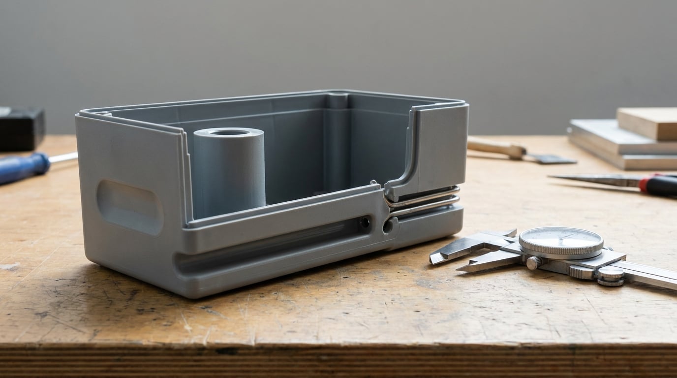
Sink marks in injection molded parts are shallow surface depressions caused by a volumetric shrinkage mismatch: the outer skin of a plastic part solidifies and shrinks while the thicker material behind it is still cooling and contracting, and the frozen surface collapses inward to absorb the difference. They show up on the face opposite a thick section, not on the thick section itself.
That last detail surprises almost everyone the first time they see it. A 4 mm wall on a housing looks fine. Add a 9 mm boss behind it and the visible face opposite that boss dips, because the boss holds enough mass to stay hot long after the skin has frozen.
This guide covers what causes sink marks in injection molded parts, how to tell them apart from voids and weld lines, and which fixes work depending on whether the real culprit is your geometry, your machine settings, or the resin. If your tool is already cut and running, jump to the diagnosis section first.
Table of Contents
- What Causes Sink Marks in Injection Molded Parts?
- How Sink Marks Form in an Injection Molded Part
- The Main Causes of Sink Marks
- How to Tell the Difference Between Sink Marks and Other Defects
- How to Diagnose Sink Marks on the Production Floor
- Fixes for Sink Marks in Injection Molding
- When to Change the Part, Mold, Resin, or Process
- Frequently Asked Questions
- Conclusion: Start with Wall Thickness, Packing, and Cooling
What Causes Sink Marks in Injection Molded Parts?
Four things drive sink, and they stack on each other. Uneven wall thickness, thick sections and abrupt transitions, packing that stops too soon, and cooling that is not symmetric across the part.
Every sink mark is the same physical event. Thermoplastics contract as they cool, and contraction scales with how much material is involved and how long it stays hot. A thick region has more volume to lose and a longer cooling time, so it keeps shrinking after the thin skin around it has already locked its shape. The gap between what the core wants to become and what the skin allows pulls the surface inward.
That is why sink concentrates in predictable places:
- Opposite a thick wall, boss, rib, or lug, on the cosmetic face the customer actually sees
- At the intersection where two ribs cross or a rib meets a wall
- At abrupt thickness steps with no radius or taper
- Where a metal insert or insert pocket concentrates mass
- Near a gate that froze off early, where the last bit of packing never arrived
- On the one cavity of a multi-cavity tool that cools differently from the others
Correction happens at three levels. Geometry comes first, because you cannot pack your way out of excess material once the gate closes. Then cooling, which sets how long the thick zone stays hot. Then the packing window, which is what the machine gives you to refill the volume that shrinkage opens up. Change them in that order and you stop guessing.
How Sink Marks Form in an Injection Molded Part
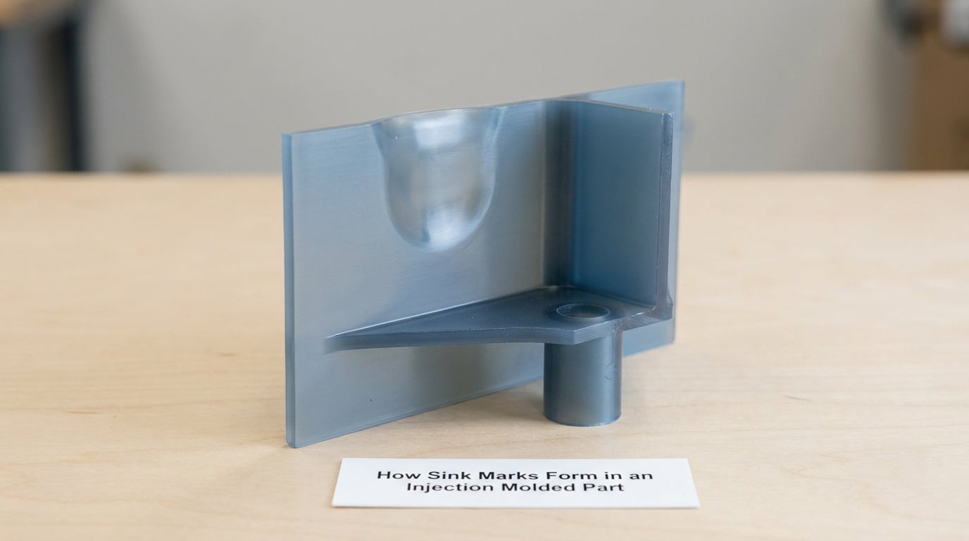
It helps to follow one shot through the cycle. Fill, pack, cool, eject. Each stage hands the next one a different problem.
Fill. Melt enters the cavity and freezes a skin on contact with the cold steel. That skin forms fastest where the part is thinnest, because thin sections have the least mass to heat.
Pack. Hold pressure is applied to push more melt into the part while the gate is still open, compensating for the shrinkage that has already happened. The useful part of packing ends the moment the gate freezes shut. Past that point, pressure has nowhere to go.
Cool. Thick sections are still well above solidification while the skin has already gone rigid. The core continues to contract on its own schedule.
Eject. The part leaves the mold, and any differential shrinkage that was stored as a residual void or a pulled-in surface finally shows itself as a depression.
Normal thermal contraction shrinks the whole part evenly, and that is what your tolerance stack-up is built around. Sink is different. It is a local volume loss with no compensation behind it, so the surface has to move to fill the space.
There are two distinct failure signatures to keep apart. A thin, shallow dip on the cosmetic face is classic differential cooling. A deep crater paired with a rough interior, or a mark that repeats with a slight silver streak beside it, points to void formation and incomplete packing, which needs a different fix.
The Main Causes of Sink Marks
Ranked by how often each one turns out to be the real culprit, based on what shows up in mold shops and contract manufacturer troubleshooting notes:
- Non-uniform wall thickness — local mass next to a thin section, the single most common source
- Thick bosses and ungated heavy regions — solid cross-section where the gate cannot pack effectively
- Rib and wall intersections — material stacking up at the junction
- Abrupt thickness transitions — a step with no radius, no taper, no blend
- Insufficient hold pressure or hold time — packing ends before the thick zone is fed
- Premature gate freeze-off — the gate closes before the heavy section is packed
- Uneven mold cooling — scaled, blocked, or badly balanced cooling circuits creating hot spots
- High-shrinkage resin or a resin running too hot — more volume to lose, and more time to lose it
- Metal inserts or pockets holding heat — local thermal mass the surrounding resin cannot outrun
Material Shrinkage and How Much the Polymer Moves
Resin choice sets the size of the problem before the mold ever fills. A grade that shrinks more leaves a larger volume gap for the skin to collapse into, so the same geometry can be acceptable in one material and rejected in another.
Typical molded shrinkage ranges, measured on standard specimens, run roughly like this:
| Resin family | Molded shrinkage (typical) | Sink tendency |
|---|---|---|
| Polypropylene (PP) | 1.5 to 3.0% | Moderate, highly flow-orientation sensitive |
| Polyethylene (PE) | 1.5 to 3.5% | Moderate, low modulus exaggerates visible dip |
| Polystyrene (PS) | 0.3 to 0.6% | Low, stiff and hard to see |
| PVC rigid | 0.1 to 0.5% | Low, unless heavily plasticized |
| PET | 0.3 to 0.9% | Low to moderate, crystallinity matters |
| ABS | 0.4 to 0.9% | Low, good surface for tight cosmetic specs |
| Polycarbonate (PC) | 0.5 to 0.7% | Low shrinkage but high mold temperature demand |
| Polyamide (PA) | 0.8 to 2.5% | High, moisture-sensitive and post-mold moving |
| Polyurethane (PU) | 0.4 to 1.0% | Low to moderate, formulation dependent |
Those numbers are a starting point, not a prediction. Shrinkage changes with filler content, regrind percentage, molecular weight, melt temperature, holding pressure, and cooling rate. A glass-filled grade shrinks far less than the neat resin figure suggests, and a semicrystalline resin like PP or PA has a larger total movement than an amorphous one like ABS because it continues crystallizing as it cools.
Two resin variables are routinely missed. Filler reduces shrinkage but raises stiffness, which sometimes makes a residual sink more visible. And regrind, if the specification allows more than a few percent, shifts both shrinkage and melt strength.
How Wall-Thickness Problems Cause Sink Marks in Injection Molded Parts
Geometry is the cause you can design out entirely, which is why it gets checked first. Three rules cover most of it.
Keep outer walls uniform. A constant wall lets the whole surface freeze at roughly the same rate. Any section that breaks that pattern becomes a local heat sink.
Size ribs against the wall they support. A rib at 40 to 60% of the adjacent wall thickness acts like part of the wall while costing a fraction of the material. A rib as thick as the wall is a thick section with a cosmetic problem.
Hollow the boss and blend it in. Coring a boss to roughly 40 to 60% of the wall removes the mass that causes the sink. Adding gussets spreads the load along the wall instead of concentrating it at one point.
Also on the checklist: radius every internal corner where walls meet, taper the transition over a real distance rather than a step, keep heavy features away from a single cosmetic face, and move inserts so the surrounding plastic is not asked to act as a heat sink for a metal block.
Mold and Processing Conditions That Worsen Sinking
Process settings do not create the local mass, but they decide how much of the shrinkage gets compensated before the gate closes.
Hold pressure and hold time. Hold time only counts until the gate is sealed. A generous hold time that extends past freeze-off buys nothing, and pushing hold pressure harder on a thick section can flash the gate, flash the parting line, or mold in stress that shows up later as warpage.
Gate size and position. A small gate, or a gate placed far from the heavy section, freezes early and strands the last part of the fill. A gate sitting on a thin wall while the mass sits across the cavity is a common way to guarantee a mark next to the boss.
Mold and melt temperature. Higher mold temperature slows skin formation, which helps on thick sections but raises cycle time and can push the part past its cosmetic tolerance. Higher melt temperature increases volumetric shrinkage. Lowering mold temperature to chase flatness is a common mistake that trades a small cosmetic gain for a dimensional one.
Cooling circuit balance. Circuits that are unbalanced, scaled with deposits, or blocked leave a hot spot, and a hot spot is a sink waiting to happen. In multi-cavity tools, the same conditions produce different results per cavity, which is a useful diagnostic in itself.
Venting and fill. A gate placed so that the last air pocket traps in a heavy region burns or stalls the fill, and a stalled fill is an underpacking problem dressed up as something else.
How to Tell the Difference Between Sink Marks and Other Defects
Misdiagnosis wastes more hours than any other step in this process. These get confused constantly:
| Defect | Where it appears | What it looks like | Root cause |
|---|---|---|---|
| Sink mark | On the surface opposite a thick section | Smooth shallow depression, glossy, repeatable in the same spot | Differential cooling and volumetric shrinkage |
| Void | Inside the part, exposed only when sectioned | Internal bubble, often rough or stretched, sometimes visible as a see-through spot | Trapped air or insufficient packing |
| Weld line | Where two flow fronts meet, often opposite the gate | Fine ridge or seam, sometimes with a slight gloss difference | Two melt streams joining with limited intermixing |
| Splay mark | On the surface, scattered | Silver streaks or fine parallel lines | Moisture, air, or volatile release from the melt |
| Burn mark | At the end of flow, near vents or the last to fill | Brown or black discoloration with a dull surface | Compressed air, no venting, or a burnt skin |
| Ejector pin mark | Exactly on a pin location | Small circular mark, often slightly proud or recessed | Draft or ejector pin condition |
| Warpage | Across the whole part | Out-of-flat, twist, or bow rather than a local dip | Asymmetric shrinkage or uneven cooling of the whole cavity |
Four observable clues separate sink from everything else. Location relative to a thick section is the strongest: if the mark sits opposite a boss or rib, it is sink until proven otherwise. A cross-section settles void questions in seconds, since a void is inside and sink is on. Viewing angle matters, because a shallow sink can vanish under diffuse light and reappear under raking light. And a defect that appears in only one cavity of a four-cavity tool points harder at cooling or gate variation than at resin.
Sectioning is destructive, so do it on a part you have already rejected rather than on a good one. If the depression is shallow and the material behind it is solid, it is sink. If there is a cavity, you are looking at a void and the process window is wrong in a different way.
How to Diagnose Sink Marks on the Production Floor
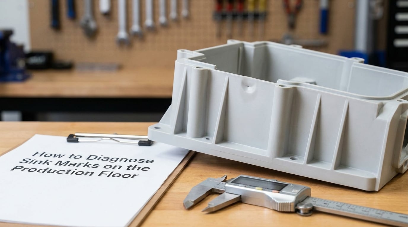
Run these steps in order. Each one rules something out, and skipping ahead is how shops end up chasing pressure settings on a part that has a geometry problem.
- Map the mark to the opposite geometry. Stand the part under raking light, mark the depression, then look directly behind it on the far side. A boss, rib, or heavy wall there confirms the mechanism.
- Pull parts from every cavity and lay them side by side. Identical marks in all cavities point to design or process. Marks in one or two cavities point to cooling balance, gate variation, or a cavity-side steel issue.
- Measure the depth. A caliper comparison against a datum and a sectioned sample tell you whether you are chasing a cosmetic dip or a dimensional change that matters downstream.
- Compare the setting sheet against what the machine is actually running. Nominal hold pressure is not delivered hold pressure at the gate, and a hold time that ends after gate freeze-off is wasted time.
- Check the gate. Compare gate size against the volume that has to be packed, and check whether a deposit or wear has restricted it.
- Inspect the cooling circuit. Look for scale, blocked passages, and circuit layouts that leave the heavy section warm. Confirm actual mold temperature at the surface rather than trusting the setpoint.
- Change one variable. Then run enough cycles to see the result, and write down what changed and what it did.
Work within the machine manual on every parameter change, and never open a mold or reach into the machine area while the cycle is running. If a setting must be raised beyond the machine’s stated range, stop and involve the equipment supplier rather than the short-term production target.
Two extra tools pay for themselves. A short-shot study, produced by holding back the shot deliberately, shows you where flow actually ends and where the last material lands. Mold flow simulation before tooling exists catches the same geometry problem in an afternoon rather than after the first trial.
Write down the part number, cavity number, cycle, machine, and the exact setting you changed. Sink is a defect that comes back every few months, and a note that says what actually worked is worth more than a general fix list.
Fixes for Sink Marks in Injection Molding
Work down this table rather than across it. The cheapest fix that works is the one that targets the real cause.
| Cause | Fix | Tradeoff |
|---|---|---|
| Thick boss next to a thin wall | Core the boss to about 40 to 60% of wall thickness and add gussets | Less fastener support and stiffness in the joint |
| Rib too thick or intersecting | Reduce rib to 40 to 60% of wall and stagger crossings | May need more ribs to carry the same load |
| Abrupt thickness step | Add a radius or a gradual blend over the transition | Takes more space in the envelope |
| Hold time ends before the thick section is fed | Extend hold time until the gate is fully sealed | Cycle time, and part weight if you overpack |
| Hold pressure too low to fill local shrinkage | Raise hold pressure in small steps within the material’s limit | Flash, molded-in stress, weight gain |
| Gate too small or too far from the mass | Resize the gate or move it toward the heavy section | Steel change and possible new balance issues |
| Hot spot from the cooling circuit | Rebalance circuits, clear scale, or drill cooling closer to the heavy section | Steel change, possibly a new insert |
| Melt or mold temperature too high | Reduce melt temperature first, then trim mold temperature carefully | Longer cycle, risk of dimensional shift |
| Resin shrinks more than the design tolerates | Specify a lower-shrinkage or filled grade, or a different resin family | Material cost and mechanical property changes |
| Residual sink on a face you cannot change | Add a matte cosmetic texture so the dip stops catching light | Hides rather than fixes, and changes the surface spec |
Texture is the pragmatic answer when the steel is already cut. A matte finish at a defined SPI or MT-11010 class breaks up the specular highlight that makes a shallow depression obvious, and it works well on Class A faces that will not tolerate a gloss surface anyway.
Machine-side changes are reversible and quick to test. Tooling changes and part redesign are slow and expensive, so reach for them only when the diagnosis says the geometry or the cooling is the cause. A resin change sits in between: it is a specification decision, not a machine setting, and it usually requires revalidating dimensions.
When to Change the Part, Mold, Resin, or Process
Here is the decision path that comes out of the diagnosis section.
Adjust the process when the mark is shallow, the geometry is already close to uniform, and the mark shows up in every cavity at the same location. Start with hold time to gate freeze-off, then hold pressure in small steps, then melt temperature. This route costs nothing and often closes the issue.
Change the tooling when the diagnosis points at cooling balance, a restricted or misplaced gate, or a thick zone the gate can no longer reach. Scaled circuits, a rebalanced cooling layout, or a new gate insert are the work here, and it usually happens while the mold is already open for something else.
Revise the part when the sectioning shows a mass ratio well beyond what packing can reach, or when the mark sits on a face that has to stay Class A. Coring the boss, reducing the rib, or blending the transition solves it permanently, and the right moment to do that is a design review rather than a trial.
Change the resin when geometry and process are already sound and the movement is simply larger than the design allows. Verify the new grade mechanically and dimensionally before committing; a lower-shrinkage material is rarely a drop-in replacement.
One caution applies to all four. Changing hold pressure, melt temperature, and cooling at the same time will leave you unable to say which one helped, and the next trial starts from a process you do not understand. Change one variable, run the cycle, record it, then move on.
Frequently Asked Questions
Are sink marks caused by the plastic material itself?
Only partly. The material sets the size of the shrinkage you are dealing with, since grades differ widely in molded shrinkage and flow behavior, but the mark itself comes from a local mismatch between a fast-frozen skin and thicker material still cooling behind it. Change resin and you change how much the problem shows, not whether your geometry invites it.
Why does increasing packing pressure sometimes make sink marks worse?
Past a point, added pressure cannot reach the thick section because the gate has already frozen shut, so the extra load shows up elsewhere: flash at the gate or parting line, molded-in stress, a heavier part, and later warpage. Packing only compensates shrinkage while material can still flow, so more pressure on a geometry problem makes the symptom louder without fixing it.
Do sink marks in injection molded parts affect strength?
A cosmetic dip on a non-structural face usually does not, because the material below it stays continuous. What matters is whether the same shrinkage has moved a boss, shifted a datum, opened a sealing land, or created a fatigue stress concentration near a fastener hole. Always check those functional surfaces before deciding a mark is cosmetic only.
How can I reduce sink marks without redesigning the part?
On existing steel, extend hold time to actual gate freeze-off, raise hold pressure in small steps within the material limit, lower melt temperature, and confirm the cooling circuits are clean and balanced. If residual sink remains on a cosmetic face, a matte cosmetic texture makes the depression far less visible under light. Steel changes and resin changes come after those steps.
When should a sink mark be treated as a mold or tooling problem?
Treat it as tooling when the mark appears in only some cavities of a multi-cavity tool, when it stays put despite verified hold pressure and hold time at the gate, or when cooling temperature at the heavy section is measurably higher than at the thin wall. Those findings point to circuit balance, deposits, or a gate that is too small or badly placed.
Conclusion: Start with Wall Thickness, Packing, and Cooling
What causes sink marks in injection molded parts comes down to one sentence: a thick region keeps shrinking after the skin around it has frozen, and the surface collapses to absorb the difference.
Start with geometry. Put a caliper on the mark and look directly behind it for the mass that caused it. Then confirm the actual hold pressure, the real hold time against gate freeze-off, and the mold temperature at the heavy section, not the values on the setting sheet.
Change one variable at a time and write down what it did. When geometry, packing, and cooling are all sound and the movement is still too large for the surface, the answer is a different resin or a texture on the cosmetic face, not more pressure.