
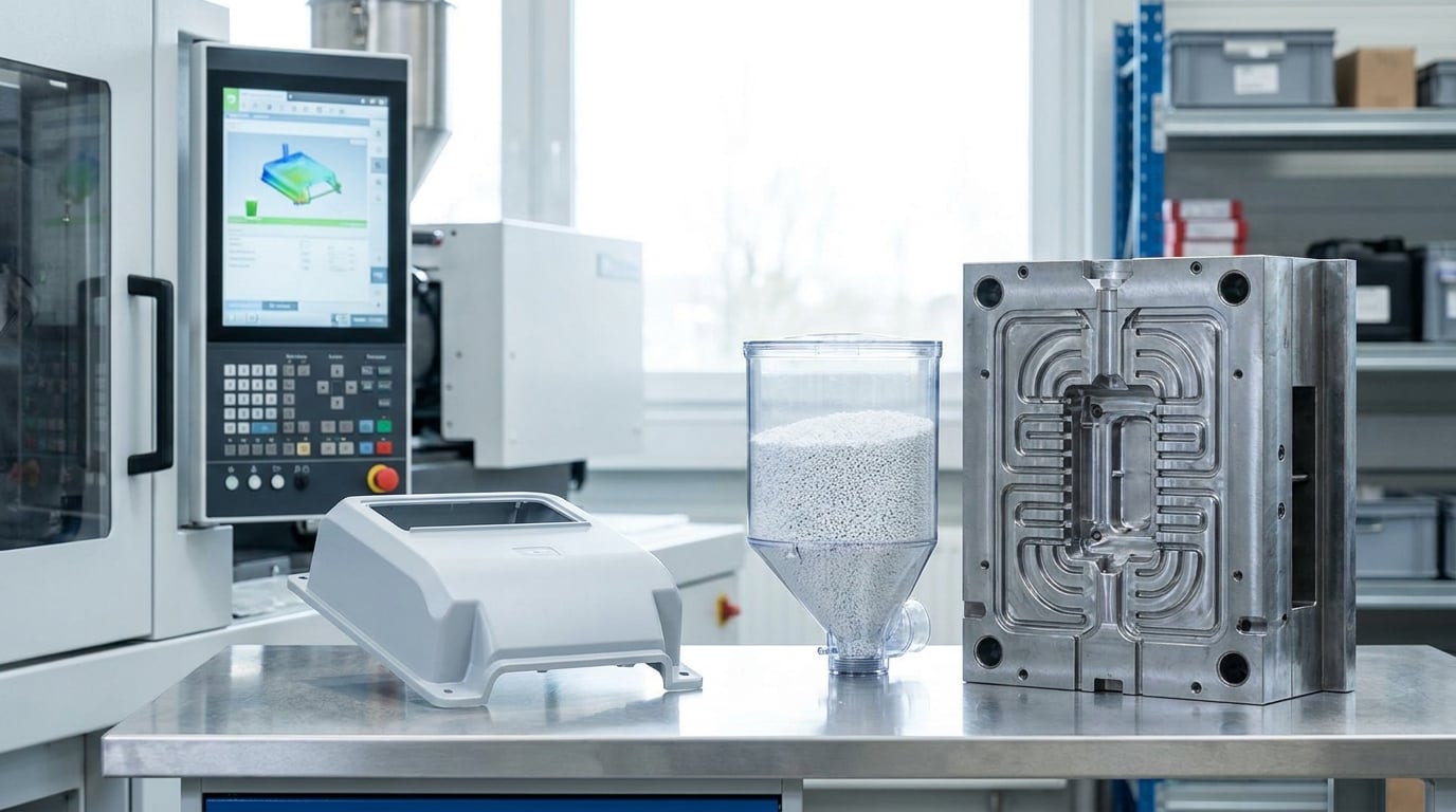
Injection molding cycle time is the total elapsed time for one complete shot: mold open, fill, hold, cooling, screw recovery, and ejection. You cut it by attacking whichever phase is actually limiting, and that phase is usually cooling, which typically takes 60 to 80 percent of the cycle. Below is how to reduce injection molding cycle time in seven ordered steps, starting with a measurement anyone can run in an hour and ending with the validation that proves the faster cycle holds up in production.
One rule governs everything below. Shorten the cycle systematically, never by shaving seconds wherever they are easiest to shave, and validate each change against fill, pack, dimensions, appearance, and defect requirements. A cycle that is 15 percent faster with 8 percent scrap is slower than the cycle you started with.
Table of Contents
- What You Need
- Step-by-Step: Reduce Injection Molding Cycle Time
- Common Mistakes
- Frequently Asked Questions
- What is the fastest way to reduce injection molding cycle time?
- How much of an injection molding cycle is cooling time?
- Can cooling time be reduced without causing sink marks or warpage?
- What machine settings most directly affect injection molding cycle time?
- Does automation always reduce injection molding cycle time?
- How should a manufacturing team validate a faster molding cycle?
- Conclusion
What You Need
You cannot improve a cycle you have not measured, so the first thing you need is a record of where the seconds actually go. The rest is supporting data that lets you tell a real bottleneck from a measurement artifact.
- Machine and mold records. Press tonnage, screw diameter, maximum injection rate, plasticization rate in kg/h, barrel capacity, nozzle size, and the mold’s hot runner or valve-gate setup.
- A current cycle-time log. Every phase timed separately for at least 20 consecutive shots, not a single hand-stopwatch reading on a good part.
- Material drying status. Drying temperature, dwell time, dew point, and the actual moisture level of the resin as it arrives at the hopper.
- Part quality requirements. Which dimensions are critical, what the sink-mark and warpage limits are, and the Cpk target the part has to hold.
- Current process settings. Melt temperature by zone, mold temperature, injection speed profile, hold pressure and time, back pressure, screw rpm, and decompression settings.
- Cooling data, not assumptions. Coolant flow rate at the tool, delta T across the circuit, and the temperature controller’s actual delivered capacity, not its nameplate rating.
- A way to measure the part. Calipers or a CMM for dimensions, a temperature probe or pyrometer for ejection temperature, and a defect inspection standard everyone agrees on.
If your plant lacks a flow meter on the cooling circuit, add one before the first trial. Forum discussions among molding engineers are consistent on this: nobody measures GPM, so the tool rarely runs at its design flow rate, and everyone assumes the cooling circuit is fine.
Step-by-Step: Reduce Injection Molding Cycle Time
Work through these in order. Each step assumes the previous one is finished, because the diagnosis in step 1 decides whether step 3 or step 5 is the right place to spend your effort.
1. Establish a Reliable Baseline
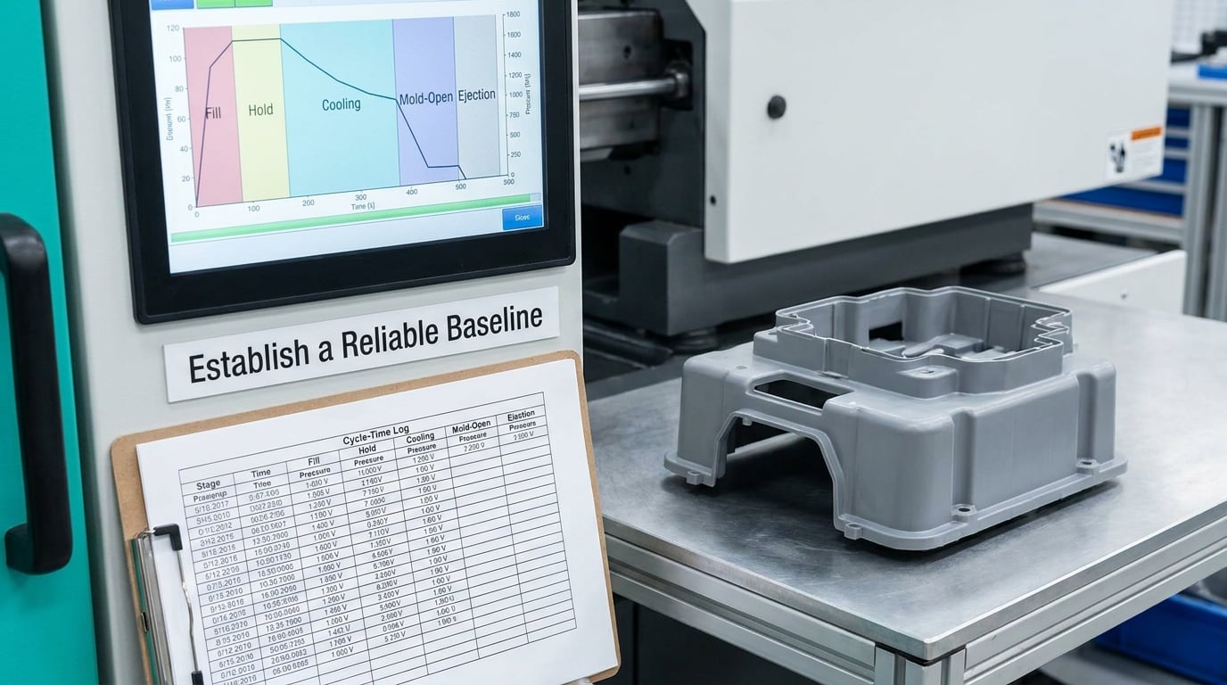
Total cycle time is the sum of mold open, mold close, fill, hold, cooling, screw recovery, and ejection. Practitioners on r/InjectionMolding split that total in two: open time, which is cooling plus mold open plus ejection, and closed time, which is fill plus hold plus recovery. Hunt for savings in each bucket separately, because the two respond to completely different levers.
Here is what a typical share of the cycle looks like. The exact numbers move with part geometry and material, so treat them as a starting picture, not a target.
| Cycle phase | Typical share of cycle | Primary lever |
|---|---|---|
| Cooling | 60 to 80 percent | Mold temperature, coolant flow, wall thickness |
| Hold and pack | 5 to 15 percent | Hold pressure and time to gate freeze |
| Screw recovery | 5 to 15 percent | Shot size vs barrel capacity, plasticization rate |
| Mold open and ejection | 3 to 8 percent | Ejector motion, draft, part removal |
| Mold close | 2 to 5 percent | Clamp speed, tie-bar clearance, mold weight |
| Fill and injection | 1 to 5 percent | Injection rate vs part weight, valve gating |
The most useful diagnostic question is simple: is the part still hot when the mold opens? If it is, the job is cooling-limited. If the screw is still plasticizing when the mold closes, the job is recovery-limited. Most shops that complain about slow cycles are actually cooling-limited and quietly losing seconds elsewhere.
Do this audit once a week, not once a year. Cycle time drifts after a mold change, a resin lot change, or a maintenance job, and nobody notices until the schedule slips.
2. Optimize Filling and Hold Without Shortening Them Unnecessarily
Fill and hold are short phases, which is exactly why they get abused. The temptation is to raise injection speed and drop hold time until the numbers look better.
Before touching either, check shot volume against part weight. A shot should use roughly 30 to 70 percent of the barrel’s usable capacity. Above that range, plasticization slows and recovery starts eating the seconds you thought you saved. Below it, you are wasting machine size.
Injection speed and melt temperature are a pair. Raising melt temperature shortens fill time but raises the energy in the part, so cooling has to remove more heat and the net saving can be zero or negative. Lowering melt temperature while holding fill time constant is often the better move, and processor experience on Eng-Tips is consistent on the mechanism: higher melt flow index grades fill at a lower melt temperature, which shortens the cooling time that follows.
Hold time is set by gate freeze, not by feel. Hold it past the moment the gate freezes and you are adding seconds for nothing. The test is a holding-pressure or gate-freeze study: hold at full pressure, then reduce pressure in steps and measure part weight and the critical dimension. The point where weight stops responding is where the gate sealed.
Cushion size is a useful check on this. A cushion that grows from 4 percent to 15 percent of screw diameter usually means hold pressure is being held longer than the gate needs, or the shot size is wrong.
3. Reduce Cooling Time Safely
Cooling is where the seconds are, so it is where the work goes. The governing variable is how much heat the part has to lose and how fast the tool can carry it away, and the tool does that through the cooling circuit.
Start with the four things you can change without touching steel: mold temperature, coolant flow rate, circuit layout, and wall thickness.
Mold temperature. Raising mold temperature shrinks the temperature difference the part must cross, which shortens solidification for amorphous materials. The catch is shrinkage and warpage: a hotter tool usually means more post-mold distortion. Run the trial, then measure the part at 24 hours, not at ejection.
Coolant flow. Flow rate matters far more than most plants assume because heat transfer in the channel depends on turbulence, not on gallons. Channels are normally designed for turbulent flow, which is why under-sized lines deliver a large penalty for a small shortfall. Parallel circuits beat long series runs because coolant arrives at every part of the tool at the same temperature and at the same time. Measure the flow and the delta T at the tool; an uneven delta T means uneven mold temperature uniformity, and uneven tool temperature is one of the most common causes of dimensional variation nobody can explain.
Circuit design. For cores, baffles and bubblers beat a straight drilled line because they push coolant along the length of the core instead of across it. Where a hot spot remains, the fix is often the steel rather than the plumbing: a higher conductivity insert such as beryllium copper in the spot where heat is pooling.
Wall thickness. Cooling time scales badly with thickness, so the biggest design lever is a uniform wall with ribs at roughly half the nominal wall thickness rather than a thick slab. Uniform thickness also removes the thick-section sink marks that tempt people to extend hold time.
A rough sizing method, useful for comparing a proposed circuit against what you have:
Heat load per hour equals part weight in pounds multiplied by resin heat content in BTU per pound per degree Fahrenheit, multiplied by the temperature swing, multiplied by shots per hour. For a 0.22 lb ABS part taken through roughly 200 degrees of swing on a 30 second cycle, that works out to a few thousand BTU per hour, which sounds alarming until you remember water moves roughly 250,000 BTU per hour per gallon per degree of delta T. Raw heat capacity is rarely the binding constraint. What actually sets cooling time is the conductivity of the mold steel and the heat transfer at the channel wall, which is why delta T and measured flow tell you far more than pump size.
Before you declare cooling time reduced, check four things: no sink marks on the thick sections, no flash, no measurable warpage after 24 hours, and ejection that releases the part cleanly. If the part needs a pry bar or a jig to come out, cooling time is too short regardless of what the cycle counter says.
4. Improve Mold Opening, Ejection, and Takeout Time
On a fast cycle, the seconds after mold open are worth real money. A two-second delay to start ejector motion, or a part that sits in the cavity while the operator reaches over, are pure loss.
Check the mold-open delay setting and the ejector stroke and return timing first, then look at draft on the part and the ejection footprint. Draft that is adequate on paper but marginal in production is a common cause of parts that drag. Air assist or vacuum assist on deep cores removes the mechanical fight of pulling a core out of a straight-walled feature.
Robotics and conveyor timing matter more than most plants assume. The overlap where the robot picks the previous part while the next cycle fills is where cycle time quietly hides. Where cycle overlap is not possible, guarding and interlocks must be upgraded before faster handling is allowed, and that is a capital decision, not a settings change.
5. Tune the Machine and Automation Sequence
Machine-side gains are usually smaller than cooling gains but come faster, and they are free once you know what you are looking at.
The main one is recovery. If the screw is still plasticizing at mold close, the press is recovery-limited, and no amount of cooling work will raise output. Recovery-limited presses show up most often on thin-wall work with a small shot in a large barrel, or on high-viscosity engineering resins. Shot size against barrel capacity, screw rpm, back pressure, decompression, and barrel zone temperatures all move plasticization rate. A documented Novatec and Pagani HDPE case is a good illustration of the direction: injecting with barrel temperature about 10 degrees C lower cut amperage by roughly a fifth and reduced the in-mold time needed for solidification, so the saving came from a cooler melt rather than from process windowing.
On the sequence side, look at nozzle size, hopper heater response, mold close speed against clamp tonnage, sensor response times, and any deliberate delays built into the machine’s open/close logic. If the machine is a hydraulic unit that has to build pressure before it can eject, cycle overlap may be capped by the hydraulics, and an accumulator or an electric machine changes that ceiling.
Changeover is the other half of the same conversation. In a high-mix plant, setup and mold change can consume a large share of available time even when the cycle itself is good. Quick mold change, standardized setup sheets, and SMED-style work on the changeover convert directly into parts per day.
6. Control Material Preparation and Drying
Material is a cycle-time variable that rarely gets treated as one, and poor preparation quietly costs seconds and quality at the same time.
Moisture in hygroscopic resins causes splay, silver streaks, and reduced strength, and the usual plant response is to extend drying dwell time as insurance. In the r/InjectionMolding discussion of recycled PET, processors lowered screw rpm to fight shear heating and raised cooling time at the same time, which pushed recovery into the limiting position, a trade-off that shows up in more shops than anyone admits. Measure moisture properly, set the dryer to what the resin needs, and stop paying for extra dwell time you do not use.
Three more levers here. A higher melt flow index grade fills at a lower melt temperature, which lowers the heat the part carries and can shorten cooling directly. Regrind ratio changes viscosity, color, and cooling behaviour, so treat it as a controlled variable with a documented ceiling rather than a per-shift decision. And room temperature is not free of influence: holding the shop floor within a few degrees is a low-cost way to keep melt and mold temperature stable, which keeps the cycle stable with it.
Feed interruptions matter as well. A hopper running low or a dryer cycling out stretches recovery unpredictably, so watch the trend rather than the average.
7. Validate the Faster Cycle
The trial protocol is the part most plants skip, and it is the difference between a real improvement and a setting nobody wants to touch again.
Change one variable at a time where the process allows it, run a controlled sample of at least 30 shots, and let the process reach steady state before you measure anything. On a short cycle, that usually means a warm-up of a few dozen shots after any temperature or speed change.
Record four things for every trial setting: cycle time from the machine, energy use per part, part dimensions and weight, and a defect inspection against your standard. Then check capability, not just conformance. A part that is in tolerance but whose Cpk drops from 1.6 to 1.05 is a part that will be out of tolerance the week the material lot changes.
Where you have the capability, run the study as a proper DOE rather than a series of single changes, and use the shop’s Scientific Molding routine to do it. Where you do not, log every cycle-time change with the date, the reason, and the resulting defect rate, so the next person inherits evidence rather than folklore.
Keep the fastest stable setting inside specification, write it down, and put the previous setting on the sheet too. That single habit has saved more production hours than most capital projects.
Common Mistakes
Most cycle-time projects fail in predictable ways, and each failure has a straightforward fix.
- Cutting cooling before measuring part temperature. Set cooling time from the ejection temperature and the thickest section, not from the cycle counter and instinct. Fix: log part temperature at mold open for a set of shots and find the time to a defensible ejection temperature.
- Raising melt temperature to shorten fill. Faster fill means more heat in the part, so cooling lengthens and the total can get worse. Fix: try a lower melt temperature with a faster injection rate, then measure the net effect on total cycle.
- Exceeding machine pressure or rate limits. Asking a press for more injection rate than it can deliver shows up as a slower cycle, not a faster one. Fix: check rated injection rate and plasticization rate against the actual requirement before promising a number.
- Changing five variables in one trial. When the result is worse, you learn nothing. Fix: one variable per trial, or a designed experiment if you have the capability to run one.
- Ignoring mold temperature stability. A tool that swings 6 degrees across the cavity produces dimensional variation that looks like a random process problem. Fix: put flow meters on the circuit and check delta T while the machine runs.
- Optimizing cycle time while ignoring the whole picture. Scrap, energy per part, and changeover time all sit in the same equation. Fix: compare cost per good part, not seconds per shot.
- Forgetting that part and mold design set the floor. A uniform wall, a balanced cavity layout, and a sensibly sized gate decide the achievable cycle before the machine ever starts.
The guardrail worth remembering through all of it: a slightly longer cycle at full good-part rate beats a short cycle with real scrap. Most experienced molders say it plainly, and the math is not close.
Frequently Asked Questions
What is the fastest way to reduce injection molding cycle time?
Start with cooling, because it takes 60 to 80 percent of most cycles. Measure coolant flow and delta T at the tool first, since an under-flowed circuit is common and cheap to fix. Then look at screw recovery, which quietly becomes the limiter once cooling is trimmed. These two levers usually deliver more than all process-setting work combined.
How much of an injection molding cycle is cooling time?
Typically 60 to 80 percent on a conventional tool, and often more on thick or semi-crystalline parts that must cool below the crystallization point before ejection. The share rises as wall thickness and crystallinity rise, and falls on thin-wall packaging running high mold temperatures. Measure your own share rather than assuming it.
Can cooling time be reduced without causing sink marks or warpage?
Yes, but the levers differ by part. On thin-wall parts, raising mold temperature and cutting wall thickness usually wins. On thick or semi-crystalline parts, the better move is a higher melt flow index grade or a larger gate so hold time can be cut. Verify sink marks, flash, and warpage at 24 hours, not at ejection.
What machine settings most directly affect injection molding cycle time?
Cooling time, hold time, decompression, screw rpm and back pressure, injection rate, and mold-open delay. Injection speed and melt temperature mainly influence how much heat enters the part, which then changes cooling. Shot size relative to barrel capacity decides whether recovery is fast or whether it caps your throughput.
Does automation always reduce injection molding cycle time?
No. Automation mainly reduces manual seconds, adds consistency, and makes cycle overlap possible, so its benefit depends on whether the machine can physically overlap steps. Where cycle time is already limited by recovery or by hydraulic response, a robot adds handling speed without raising output. Faster handling can also require better guarding before it is allowed.
How should a manufacturing team validate a faster molding cycle?
Run controlled trials of at least 30 steady-state shots per setting, changing one variable where possible. Record cycle time, energy per part, part weight, critical dimensions, and a defect inspection for each. Then compare capability before and after, so you catch a Cpk drop that conformance sampling would miss. Keep the fastest stable setting and log it.
Conclusion
For most plants the first move is simple: time every phase of the cycle for 20 shots, find the largest stage you actually control, and change one thing about it. If the answer is cooling, start with measured coolant flow and delta T rather than a process setting. Then validate the faster cycle against part weight, critical dimensions, and capability before you scale it across the cell.