
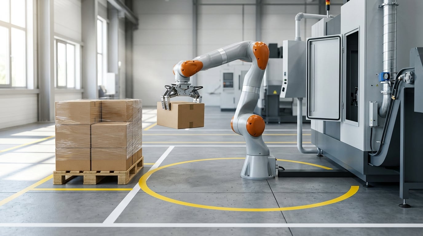
To size robot payload and reach, you measure the real mass at the wrist flange, measure how far the tool has to travel from the robot’s base through every position it will visit, then add margin to both numbers before you open a catalog. Rated payload and rated reach are peak figures taken at different, favourable configurations, so a robot that technically passes both tests can still oscillate at the far end of the cell. The work is arithmetic on your own layout, and it takes an afternoon, not a catalogue weekend.
Here is the method integrators use: build the cell specification, convert the layout coordinates into a required reach, derate that reach so the usable envelope is roughly half to three-fifths of the published figure, total the payload including every gram of tooling, add 20 to 30 percent headroom, and finally check wrist inertia against the manufacturer’s allowable value. Manufacturers such as Fanuc, ABB, Yaskawa, KUKA, Epson and Universal Robots all publish reach, payload, wrist inertia and repeatability in the same datasheet layout, which is what makes this comparison possible at all.
Table of Contents
What You Need
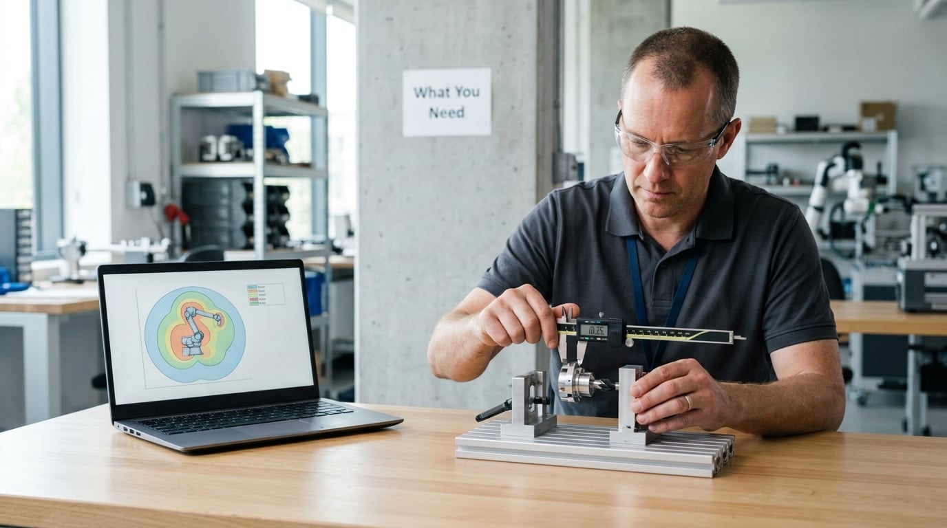
Before any of that arithmetic, you need a layout with real numbers on it. Not a sketch, not a photo of the floor, a dimensioned plan that says where the infeed, the fixture, the pedestal and the drop-off points sit relative to the spot the robot will occupy. People on the robot-forum boards reach the same conclusion: draw the layout or a CAD model of infeed, pallet and robot position first, and only then work out which model can reach it.
From that layout, collect six groups of information:
- Mass at the flange in every pose the cell will use, with the workpiece, tooling, cables and fittings itemised rather than estimated as a round number.
- Load centre of gravity, meaning the distance from the tool flange face to the centre of the combined load, in millimetres.
- Required reach, both the farthest and the nearest point of the cycle, measured as a straight line from the robot’s reference axis.
- Cycle time and takt, plus how long a single pick, transfer and place is allowed to take.
- Accuracy and repeatability targets derived from the process tolerance, not from what a machine happens to offer.
- Environment and mounting: weld spatter, coolant, dust, washdown, wash-down chemicals, ambient temperature, and whether the arm bolts to the floor, a pedestal, a wall, a riser or a rail.
| Input | How to get it | What it decides |
|---|---|---|
| Total mass at flange | Weigh the assembled tool and workpiece, or sum manufacturer weights | Which payload class the arm must come from |
| Load centre of gravity offset | Measure flange face to the centre of the tool | Whether the wrist can move it, and wrist inertia |
| Maximum and minimum required reach | Dimensioned layout, measured from the axis-2 centreline | Published reach you must spec, before derating |
| Stack or process height | Highest point of the finished product or the part | Vertical envelope and rear-quadrant clearance |
| Cycle time | Takt from the process, plus settling time | Whether the model is fast enough, independent of size |
| Repeatability requirement | Process tolerance, divided across part features | Accuracy class, and whether a cobot will do |
Robot Payload and Reach: Step-by-Step
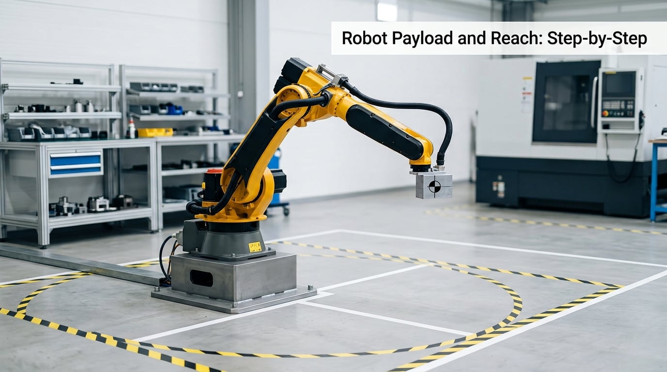
Payload and reach are not two independent filters applied one after the other. They are evaluated together, because the load a robot can hold changes as the arm extends, and the extension available changes as the load gets heavier. Sizing is the process of finding the arm whose payload curve at your longest working distance still clears your load, with margin, while clearing every obstacle in the cell.
1. Define the Task and End-of-Effector Load
Start by writing down everything that moves with the flange. The workpiece, obviously. Then the gripper body, the fingers or suction cups, the adapter plate, the hose bundle looping over the wrist, cable connectors, proximity sensors, and any part-present sensor or air fitting. On a typical machine-tending cell the workpiece is 6 kg and the tooling comes to 7 kg, so half the load is the part you came to move.
Then separate static mass from process force. A robot welding a 4 mm fillet is not just holding 9 kg; the torch adds an offset force in whatever direction the process pushes. Extrusion, dispensing, pressing and heavy machining all add forces that do not show up on a scale. Note them as an additional directional load at the tool, because they consume wrist torque even though they add no mass.
Finally, record the load centre of gravity. It is the distance from the flange face to the point where the combined mass acts, and it is the number that turns a mass specification into a moment specification. A long extension gripper and a short vacuum plate carrying the same part have very different behaviour on axes 4, 5 and 6, even at identical mass.
2. Measure the Required Reach
Published reach is measured from a specific reference point, usually the centreline of axis 2 rather than the front face of the base plate. If you measure from the edge of the base or the centre of the column, your number will be short by 200 or 300 mm and the shortfall shows up in the cell, not on paper. Check the datasheet drawing for which axis the reach dimension starts at, and check whether it is quoted in millimetres or inches.
Measure in three directions, not one. The horizontal distance from the robot reference axis to the farthest infeed or pallet position, the vertical rise to the top of the stack or the machine tool point, and the radius to any position the cycle touches at full extension. Do this for the approach, the transfer, the inspection or process, and the retreat. A robot that reaches the pick position comfortably can still fail at the place position if the pallet is diagonal to its base.
Then take the raw figure and derate it. Plan on the usable envelope being about 50 to 60 percent of published reach, and spec up by a factor of 1.5 to 2 against your measured requirement. If the layout needs 1,400 mm, spec a robot at 2,300 mm or more. That derate buys you three things: room to keep the wrist off its singularity, margin for layout drift when the fixture is not exactly where the drawing said, and clearance from the rear quadrant where the robot’s own column and upper arm can foul the approach.
3. Calculate Payload with a Safety Margin
The payload budget is a simple sum, and it is the step most often got wrong:
m_total = part + gripper body + fingers or cups + adapter plate + cabling + fittings
Worked example. A 12 kg casting, a 7.5 kg parallel gripper with fingers, a 1.2 kg adapter plate, 0.8 kg of dress pack looping over the wrist, and fittings bring 21.5 kg at the flange. Add 25 percent headroom and you need 26.9 kg of rated payload, so you are shopping in the 30 to 35 kg class rather than the 20 kg class, even though the part itself is 12 kg. Run the cycle in continuous duty and push the margin to 30 percent, because motor thermal limits bite long before the mechanical ones do.
The 20 to 30 percent band is a rule of thumb with a reason behind it. It absorbs product variation, a gripper that gets swapped for a heavier one six months after commissioning, and the acceleration loads that never appear in a static mass figure. A 10 kg-rated arm loaded to 10 kg all shift is a machine that will report overcurrent faults and start wearing wrist bearings early.
Payload class bands give you a quick sanity check on the answer:
| Class | Typical rated payload | Typical applications |
|---|---|---|
| Light | 3 to 20 kg | Pick and place, machine tending, small assembly, screwdriving |
| Medium | 20 to 120 kg | Machine loading, welding, heavier tending, single-pallet handling |
| Heavy | 120 to 800 kg | Palletizing, layer and bag grippers, multi-pallet patterns |
If your computed load lands just under the top of a band, treat that as a reason to move up one size rather than a reason to relax. The costs of an undersized arm are downtime and scrap; the cost of a slightly larger arm is floor space.
4. Check Reach at the Load Center of Gravity
Here is where nominal figures stop being useful. A robot’s allowable payload is normally specified at a wrist distance shorter than its maximum reach, and the allowable mass falls as the tool extends away from the flange. The relationship is a moment: mass multiplied by distance multiplied by gravity. The same 25 kg load is trivial at 100 mm and marginal at 400 mm, which is why you must read the payload-versus-wrist-distance curve in the datasheet rather than the headline number on the front page. Orientation matters too, as does mounting angle, because a robot bolted to a wall or an angled pedestal does not present the same gravity vector to the wrist as one standing on the floor.
Mass alone is not enough either. The wrist also has to accelerate the load, and that is a function of inertia:
J_effective = J_gripper + m x L²
where m is the mass carried at the flange and L is the distance from the wrist rotation axis to the combined centre of gravity. Take a 4 kg gripper whose centre sits 150 mm out from the wrist axis. Four times 0.15 squared gives 0.09 kg·m² before you add the gripper’s own inertia about its own axis, which pushes the figure higher. Compare that with the manufacturer’s allowable wrist inertia for axes 4, 5 and 6, and if you exceed it you have three options: shorten the offset, lighten the tool, or move to a model with a higher inertia rating. Ignoring this is a common cause of vibration near the edge of the envelope that looks like a controller or mechanical problem.
Two more things change the numbers. Process forces, as in welding or dispensing, add to the wrist load in the direction of the process. And a 7th-axis rail or floor track extends the arm’s working range, but the rail’s own mass and the offset it creates at axis 1 add to the effective inertia that axis has to move, so the rail is not a free extension of capability.
5. Validate Speed, Cycle Time, and Accuracy
Size and speed are separate budgets, and a robot can pass every load test while missing takt. Add up the individual moves in the cycle, include acceleration and deceleration on each axis, and add settling time after fast moves. Compare the total with your takt. The practical rule is to validate cycle time on the shortest model that meets your load and reach, because extra reach usually means a longer, heavier lower arm and slower moves.
Check repeatability against your process tolerance, and accuracy where the feature matters. Stacking a carton needs repeatability, not accuracy. Placing a bolt into a threaded hole on a machined flange, or welding a seam on a body that will be visible, needs absolute accuracy over the whole working range. Both are quoted in the datasheet, and ISO 9283 is the standard that defines how they are measured, so comparing two makers on a spec sheet is fair as long as you know which number you are reading.
6. Check the Application and Select the Model
With payload, reach, inertia and cycle time settled, the class usually falls out on its own:
| Class | Typical reach | Typical payload | Good fit | Watch out for |
|---|---|---|---|---|
| Articulated | 1,000 to 3,000 mm | 5 to 800 kg | Machine tending, welding, palletizing, general work | Size creep, rear-quadrant limits, wrist inertia |
| SCARA | 300 to 1,000 mm | 0.5 to 20 kg | High-speed pick and place, screwdriving, assembly | Limited vertical reach, poor with heavy or awkward parts |
| Collaborative | 500 to 1,800 mm | 3 to 35 kg | Short runs, low-volume tending, cells sharing space with people | Speed and force limits, unsealed joints in coolant or dust |
| Delta | 600 to 2,000 mm | 0.5 to 15 kg | Very fast light pick and place | Light parts only, poor with off-centre loads |
| Linear / gantry | Several metres | Varies widely | Long travel, wide areas, heavy or bulky products | Less flexible wrist orientation, takes floor space |
Count the axes you actually need rather than buying the most. Four axes cover a palletizer placing cartons on a level pattern. Six cover machine tending, welding and any job that changes the tool angle between stations. SCARA and delta arms are typically four-axis. A cobot’s 4 kg-rated arm is not a scaled-down 50 kg arm, because the collaborative safety model is what limits how fast and how hard it can move.
Also decide the mounting early. A pedestal or angled riser changes the usable envelope and the effective payload at each pose, and it has to be in the foundation design. Then check protection for the actual environment, controller connectivity to your PLC network, the availability of parts and service, and the duty cycle the model is rated for. And keep the hobby and academic arms in view as a boundary: desktop and kit arms are fine for prototyping light pick-and-place, but the rails, bearings and wrist inertia of a 1,500 mm class of academic arm are why the same sizing method produces a different answer than it would for a production cell.
Common Mistakes
Most sizing errors are not arithmetic mistakes, they are omissions. Each one below has a signature in production that tells you which omission you are looking at.
| Pitfall | Symptom in production | Fix |
|---|---|---|
| Using nominal payload at full extension | Overcurrent faults at the far end of the cycle, thermal trips after an hour | Read the payload-versus-wrist-distance curve, not the headline rating |
| Forgetting the tooling in the budget | Load exceeds rating once the real gripper is fitted | Total part, gripper, fingers, plate, cabling and fittings, then add margin |
| Measuring one position only | Robot cannot place into the far corner, or fouls the fixture on approach | Measure approach, transfer, process and retreat positions |
| Ignoring the load centre of gravity | Vibration and long settling near full extension, repeatability drifts with load | Compute J_effective = J + m x L² and check against allowable wrist inertia |
| Wrist inertia left unverified | Buzzing in the wrist, oscillation worse at speed than at rest | Shorten the tool offset or move up a class |
| Treating reach as reachability | Arm hits the fence, the fixture or its own rear quadrant | Derate to 50 to 60 percent usable, and plot the work quadrant |
| Skipping cycle time | Robot fits the load but misses takt once settling is included | Time every move with accel, decel and settling before finalising |
| Buying on nominal size from the used market | You end up with an arm much larger than the cell needs | Size from the layout first, then shop; accept a coarse match knowingly |
That last one is worth dwelling on. Buyers on r/robotics regularly report ending up with an older arm bigger than the job strictly required, simply because used inventory is coarse-grained and a near-match is easier to buy than an exact fit. Budget for that: the arm you can get may be a class above your calculation, which is fine if you priced it that way, and expensive if you did not.
Two smaller habits separate a defensible spec from a hopeful one. Do a reduced-speed dry run before the first production part, so a collision shows up at walking pace rather than at full speed with a fixture attached. And verify repeatability with a simple dowel pin or a test coupon in the tool, which costs an afternoon and tells you whether the accuracy figure in the datasheet survives your actual tool and load.
Frequently Asked Questions
What is the payload capacity of a robot?
Payload capacity is the total mass an industrial robot can carry at its wrist flange, and it includes everything mounted there, not just the workpiece. That means the gripper body, fingers or suction cups, adapter plate, dress-pack cabling and fittings. Manufacturers rate the figure at a defined wrist distance, which is usually shorter than the arm’s maximum reach, so allowable payload falls as the tool extends. Always read the payload-versus-distance curve.
What is the work envelope in robotics?
The work envelope is the three-dimensional volume of space the tool centre point can reach. It is bounded by the robot’s geometry, its own body, the wrist singularity where two axes line up, and anything else in the cell such as fences, fixtures and machines. Published reach is a single maximum dimension of that volume, measured from a reference axis such as the axis-2 centreline. In practice you can rely on roughly 50 to 60 percent of published reach for real work.
How much weight can robots lift?
It depends on the class. Collaborative arms run about 3 to 35 kg, mid-size articulated arms about 20 to 120 kg, and heavy palletizers 120 to 800 kg. The number that matters is the rated payload at the reach your cell needs, with 20 to 30 percent headroom over your computed load of part plus tooling plus cables. Nominal maximum payload at minimal extension tells you very little about your application.
Does gripper weight count toward robot payload?
Yes, entirely. Every kilogram at the flange counts, including the gripper body, fingers, adapter plate and the cabling that loops over the wrist. On many machine-tending cells the tooling outweighs the workpiece. It also affects wrist inertia, so a heavy gripper mounted far out on an extension can exceed the allowable inertia for axes 4, 5 or 6 even when the mass itself is within the payload rating.
How do I know if my robot is undersized?
Watch for overcurrent and thermal alarms that appear only at the far end of the cycle, vibration that worsens at full speed, settling times longer than the datasheet implies, and repeatability that drifts when the load changes. Those are the classic signatures of a robot running at the edge of its payload or wrist-inertia rating. Add 20 to 30 percent headroom, derate reach to 50 to 60 percent of published, and verify against the payload and inertia curves before buying.
Should I choose a 7th-axis rail or a larger robot to get more reach?
A rail or floor track extends the working range far beyond a bigger arm at a fraction of the cost, and it suits cells with several stations spread along a line. The trade-offs are a larger footprint, an extra axis to integrate, and added effective inertia at axis 1 from the carriage mass and offset. A larger robot keeps the work envelope compact around the base and usually has better repeatability. Choose the rail for reach over distance, the bigger arm for reach around a tight point.
Conclusion
Your first action is documentation, not shopping. Write down the complete load at the flange, including every piece of tooling, and measure the required reach from the axis-2 centreline to the farthest and nearest point of the cycle. Add 20 to 30 percent to the load, spec reach up by a factor of 1.5 to 2, and check the result against the manufacturer’s payload-versus-distance and wrist-inertia curves. That is a spec you can defend in front of a vendor, and it is much harder to get wrong.