
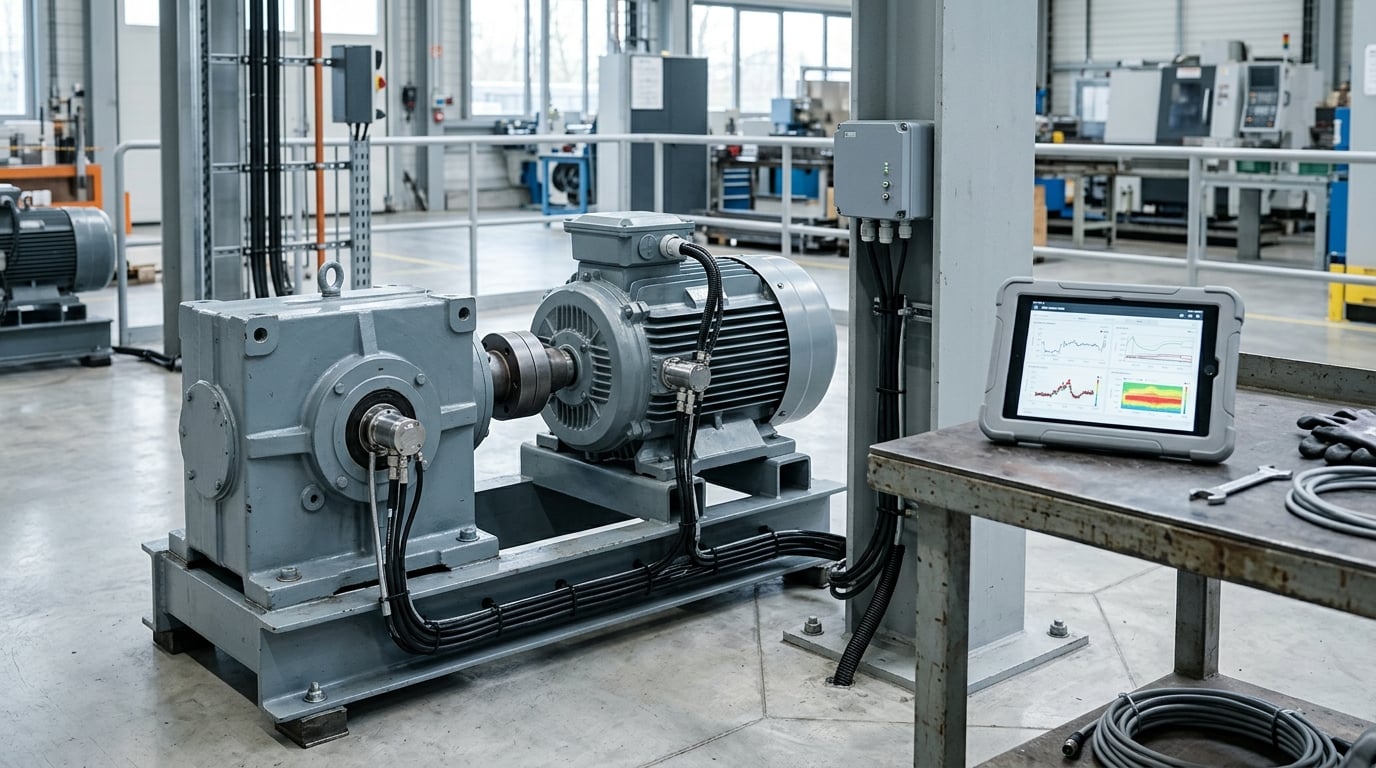
Predictive maintenance sensors for factory equipment are vibration, temperature, acoustic, pressure, current, and oil-condition devices mounted on motors, pumps, gearboxes, compressors, and other assets. They measure degradation continuously, so maintenance teams schedule repairs from real data instead of a calendar. This guide covers what each sensor catches, where it goes, and how alerts turn into work orders.
If you are evaluating this for a plant, the biggest mistake is starting with hardware. Sensors are the easy half. The half that decides whether the program survives contact with a maintenance department is what happens to the alert after it fires.
Table of Contents
- Predictive Maintenance Sensors for Factory Equipment
- How Predictive Maintenance Sensors Work
- Which Factory Equipment Can Benefit From Sensors?
- What Types of Predictive Maintenance Sensors Are Best?
- How to Choose Predictive Maintenance Sensors for Factory Equipment
- Wireless, Wired, and Hybrid Sensor Systems
- How to Install and Calibrate Predictive Maintenance Sensors
- How to Connect Sensors to a Condition-Monitoring Platform
- How to Turn Sensor Alerts into Maintenance Actions
- Common Mistakes and Troubleshooting
- Frequently Asked Questions
- What are predictive maintenance sensors for factory equipment?
- Do older machines need to be replaced to use predictive maintenance sensors?
- Are wireless sensors reliable enough for critical factory equipment?
- How often should predictive maintenance sensors be calibrated?
- How do manufacturers calculate predictive maintenance ROI?
- Conclusion
Predictive Maintenance Sensors for Factory Equipment
A predictive maintenance sensor is a physical measuring device that sits on or near a machine and reports a signal that changes as the machine degrades. Condition monitoring is the practice of reading those signals to decide when a repair is due.
The distinction from other maintenance styles matters more than any spec sheet. Scheduled maintenance repairs a machine on a fixed interval whether or not it needs it. Reactive maintenance waits for the breakdown. Condition-based maintenance intervenes when a measurement crosses a threshold, and predictive maintenance adds trend analysis so the trigger looks ahead rather than waiting for the threshold itself.
What are the 3 Ps of maintenance?
- Preventive maintenance runs on a calendar or hour counter set by the manufacturer or by history. It reduces breakdowns but still replaces healthy parts and cannot respond to a machine that is degrading faster than the schedule assumes.
- Predictive maintenance intervenes based on measured condition, using thresholds at first and trend or model-based detection later. The work happens while the machine is still running, usually with a shutdown window already planned.
- Prescriptive maintenance tells the crew what to do about it: which part, which procedure, which crew, in what order. It needs the asset registry, spare parts data, and CMMS integration that a predictive program produces.
Practitioners rarely run one strategy alone. A mature plant keeps preventive tasks for lubrication, filters, and safety items, adds predictive monitoring for degradation, and lets prescriptive logic handle the scheduling.
How Predictive Maintenance Sensors Work
The workflow is the same everywhere, whether the sensor is a simple surface-mounted thermocouple or a networked triaxial accelerometer. Data gets collected, compared against a baseline for that specific asset, and acted on only when the comparison says something changed.
| Stage | What happens | Who or what does it |
|---|---|---|
| Placement | Sensor mounted on the bearing housing, motor terminal box, pipe, or gland at the point where the failure signature is strongest | Reliability or maintenance technician |
| Collection | Signal sampled at a fixed interval, from a few hertz for slow thermal drift up to tens of kilohertz for bearing defect frequencies | Sensor and transmitter |
| Transport | Reading sent over a 4-20 mA loop, RS-485, Modbus TCP, OPC-UA, or a wireless protocol such as LoRaWAN, BLE, Wi-Fi, or LTE-M | Edge gateway or network gateway |
| Baseline | Normal operating signature captured for that asset in its normal state, usually across several load conditions | Platform or route-based analyst |
| Detection | Reading compared to the baseline and to ISO 10816 or ISO 7919 severity zones; models flag deviation from expected pattern | Analytics layer |
| Action | Alert routed to the responsible technician and, where configured, converted into a work order in the CMMS | Maintenance planner or CMMS |
The baseline step is where most programs stumble. A baseline captured while the machine is loaded differently from production, or on a cold morning, teaches the system that abnormal is normal.
Which Factory Equipment Can Benefit From Sensors?
Almost any rotating asset with a failure mode that shows up in a measurable signal. The practical filter is whether the failure produces a warning you can act on early and whether a spare and a crew exist for it.
- Motors take temperature at the stator windings and bearing housings, plus vibration at the drive end. Catches imbalance, misalignment, bearing wear, and winding insulation decay.
- Pumps take vibration at the casing and bearings, and suction or discharge pressure. Catches cavitation, impeller wear, dry running, and bearing failure.
- Fans and blowers take vibration and bearing temperature. Catches imbalance, blade fouling, and bearing wear, which usually shows up in vibration before anything else moves.
- Air compressors take discharge pressure and temperature, vibration on the crank and motor ends, and current. Catches valve wear, air-end degradation, and cooling fouling.
- Presses and hydraulic systems take pressure, temperature, and valve position. Catches relief valve drift, hydraulic leaks, and ram alignment problems.
- Conveyors and gearboxes take vibration at the drive and idler bearings, plus motor current. Catches belt wear, bearing defects, and gearbox tooth wear.
- Chillers, HVAC, and refrigeration take suction pressure, discharge temperature, current, and flow. Catches compressor issues, charge loss, and fouled heat exchangers.
- CNC and injection molding machines take spindle vibration, drive current, hydraulic pressure, and nozzle temperature. Catches tool wear, servo faults, and barrel heater failure.
Where should you start? Rank assets by downtime cost, by whether a failure takes safety or quality with it, and by whether a spare is on the shelf. One high-cost pump line beats twenty low-cost units, and you can prove the program on one asset class before you scale.
What Types of Predictive Maintenance Sensors Are Best?
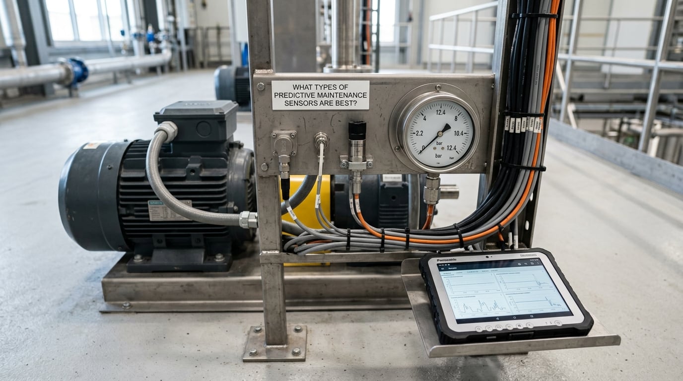
There is no best sensor, only the best sensor for a failure mode and a machine. These eight families cover most factory condition monitoring work.
Vibration sensors (accelerometers)
The workhorse of condition monitoring and usually the first sensor a plant installs. Vibration sensors catch imbalance, misalignment, looseness, bearing defects, and gear wear, usually weeks before anything visibly fails. Three main types exist: piezoelectric accelerometers, which are rugged and cover high frequency but cannot measure static or very low frequency; MEMS accelerometers, which cover DC to a few kilohertz, are cheaper, and now dominate wireless route monitoring; and servo or velocity transducers, slower but still the reference for ISO 10816 severity zones in heavy rotating machinery.
Strong signal, widest failure coverage. Weaknesses: needs a solid mounting surface, needs the right frequency range for the machine speed, and gives you nothing on a slow-moving fault.
Temperature sensors (RTDs and thermocouples)
The simplest reliable signal there is. RTDs such as PT100 give accuracy and stability over long ranges; thermocouples cover wider and hotter ranges and tolerate rough environments better. Temperature catches lubrication failure, cooling blockage, electrical connection resistance, and bearing or winding overheating.
Cheap and hard to fool, but it is a lagging signal. By the time a bearing runs 20 degrees above baseline, damage is usually done, so thermal alone gives shorter warning than vibration. For electrical panels, infrared thermography is a different and very high value tool: it inspects hundreds of connections in an hour without touching energized equipment.
Oil and lubricant condition sensors
The most underused category in factory condition monitoring. Viscosity, dielectric constant, water content, particle count, and elemental wear-metal content tell you whether the lubricant is still doing its job. This catches lubricant degradation, water ingress, additive depletion, and gear or bearing wear that would otherwise show up as a slow vibration change nobody can separate from process variation.
Worth it on gearboxes, turbines, compressors, and any sump-fed system. The limitation is that it samples slowly and needs a fluid path or a portable analyser route rather than continuous mounting.
Acoustic emission and ultrasonic sensors
Acoustic emission sensors listen for the high-frequency sound of a defect forming. They catch lubrication breakdown, cavitation, and leaks in the inaudible ultrasonic band, which is why steam traps, valves, and gearboxes respond well. Ultrasonic inspection cameras and handheld units cover bearing and lubrication checks without contact.
Excellent for leaks and lubrication, harder to interpret than vibration, and sensitive to background noise, which in a loud plant means careful filtering.
Pressure and flow sensors
Pressure transducers and flow meters catch hydraulic pressure loss, filter blockage, cavitation, pump wear, and leaks in lines that no vibration sensor can see. On chillers and refrigeration systems, suction pressure and superheat readings identify a failing compressor before it trips.
Direct process measurement, easy to baseline, and often already instrumented on the asset. The limitation is range and material compatibility: slurry, steam, and corrosive service need specific wetted parts.
Current and power quality sensors
A current transducer clamped on one conductor gives you motor load, unbalance, and inrush without touching the machine mechanically. Current signature analysis identifies a motor working against a mechanical fault because the motor is compensating, which makes it a useful cross-check on vibration data.
Easy to install, no downtime needed, and covers electrical faults such as phase loss and rotor bar problems that mechanical sensors miss.
Position and displacement sensors
Proximity probes, encoders, laser sensors, and linear transducers measure shaft position, runout, and alignment on high-speed or high-precision machines, and they verify that a valve or ram actually reached its commanded position.
Precise, but installation is fussy and the applications are narrower than the rest of this list.
Humidity, corrosion, and environmental sensors
Less glamorous and occasionally decisive. Humidity and dew point sensors prevent condensation corrosion in electrical enclosures and rooms. Corrosion and conductivity sensors cover marine, food, and washdown environments.
Keep these in mind when an IP-rated enclosure choice matters as much as the measurement.
How to Choose Predictive Maintenance Sensors for Factory Equipment
Work through the failure mode before you work through the catalog. Start with the specific failure you want to catch, then choose the signal that carries it, then pick the model that survives that mounting location.
| Failure mode | Best measurement | Best-fit equipment | Typical warning lead time | Relative cost |
|---|---|---|---|---|
| Rolling and ball bearing wear | Vibration at the bearing housing | Motors, pumps, gearboxes, fans, conveyors | Weeks to months | Mid |
| Imbalance and misalignment | Vibration, optionally paired with current | Rotating equipment, fans, pumps, shafts | Days to weeks | Mid |
| Overheating and cooling loss | Temperature, infrared thermography | Motors, gearboxes, electrical panels, chillers | Days to weeks | Low |
| Lubricant degradation and water ingress | Oil viscosity, water content, particle count | Gearboxes, compressors, turbines, sump systems | Weeks to months | Mid to high |
| Hydraulic pressure loss and leaks | Pressure, flow, ultrasonic | Presses, hydraulic power units, presses’ hydraulic systems | Days to weeks | Low to mid |
| Cavitation and pump degradation | Suction and discharge pressure, vibration | Pumps, boiler feed pumps, water treatment | Days to weeks | Mid |
| Electrical faults and motor overload | Current, power quality | Motors, switchgear, transformers, compressors | Days to weeks | Low |
| Steam trap and valve leakage | Ultrasonic, acoustic emission | Steam traps, valves, piping, relief valves | Weeks | Low to mid |
Then check the practical specs, because this is where a good sensor becomes a failed install.
- Measurement range and sampling rate. A vibration sensor sampled too slowly misses bearing defect frequencies entirely. Match the frequency response to the machine speed, and match the temperature range to the machine with headroom.
- Environment. IP rating, temperature rating, chemical exposure, washdown, dust, and cast iron dust near machining areas. Ingress protection ratings are the first thing to check on any sensor mounted outside a cabinet.
- Mounting method. Threaded stud, adhesive pad, rare-earth magnet, or clamp. Vibration sensors need rigid coupling to the structure, and a magnet mount on rough cast housing is a permanent source of noise. Where a grease nipple sits is often a usable flat spot.
- Communications and power. Wired 4-20 mA or RS-485 for reliability and no batteries, wireless for installation speed and no cable trays.
- Calibration and traceability. A sensor with documented calibration and a certificate is worth more than one without. Also confirm whether the platform handles the scaling and unit conversion for you.
- Total cost, not unit cost. Installation labour, gateways, software, network drops, and battery logistics all count. A cheap sensor with a yearly battery swap in a hard-to-reach location is not cheap.
What predictive maintenance sensors for factory equipment cannot detect
Some failure modes are not visible in any sensor signal. A cracked motor winding that fails from a manufacturing defect, a control system fault, a hydraulic hose that bursts between readings, a mechanical seal that lets go suddenly, and software or sensor wiring faults inside a cabinet are all outside the reach of condition monitoring.
Practitioners on maintenance forums report that a large share of failures stay unplanned even after a condition monitoring rollout, mostly because these causes are not sensor-detectable at all. Treating a sensor program as the answer to every breakdown is how budgets get wasted.
Wireless, Wired, and Hybrid Sensor Systems
Every deployment ends up in one of three architectures. The honest answer is that most real plants run all three at once.
| Factor | Wired | Wireless | Hybrid |
|---|---|---|---|
| Signal reliability | Highest, immune to interference | Good indoors, degrades in large plants and around metal structures | Highest where it matters most |
| Install time per point | Long, needs cable routing and terminations | Minutes, no trenching | Mixed |
| Power | Loop or bus powered, no batteries | Battery, coin cell or lithium, replaced on a schedule | Mixed |
| Coverage limits | Cable length | Dead zones, range per gateway, message rate limits | Depends |
| Cybersecurity surface | Minimal, physically secured | Radio traffic, key management, device identity | Manage both |
| Scalability | Limited by cable infrastructure | Limited by gateway density and radio planning | Scales asset class by asset class |
| Best use case | Continuous critical machines in a fixed layout | Retrofit, temporary monitoring, hard-to-reach assets | Most plants over time |
Wireless protocols are not interchangeable. Bluetooth Low Energy suits route-based handheld collection at short range. LoRaWAN covers a whole building or yard on very little power, so battery life runs years, which suits low-frequency thermal and slow vibration reporting. Wi-Fi is fine if the plant already has dense coverage, but congest quickly with dozens of nodes. LTE-M and NB-IoT work across a multi-building site without a private network, with per-device cellular cost.
Route-based collection deserves a fair mention too. A technician walking a monthly route with a handheld analyser and a grease-gun-mount pickup still catches early bearing defects in a well-run plant. Continuous networked sensors beat that on frequency and on the fact that nobody has to remember.
How to Install and Calibrate Predictive Maintenance Sensors
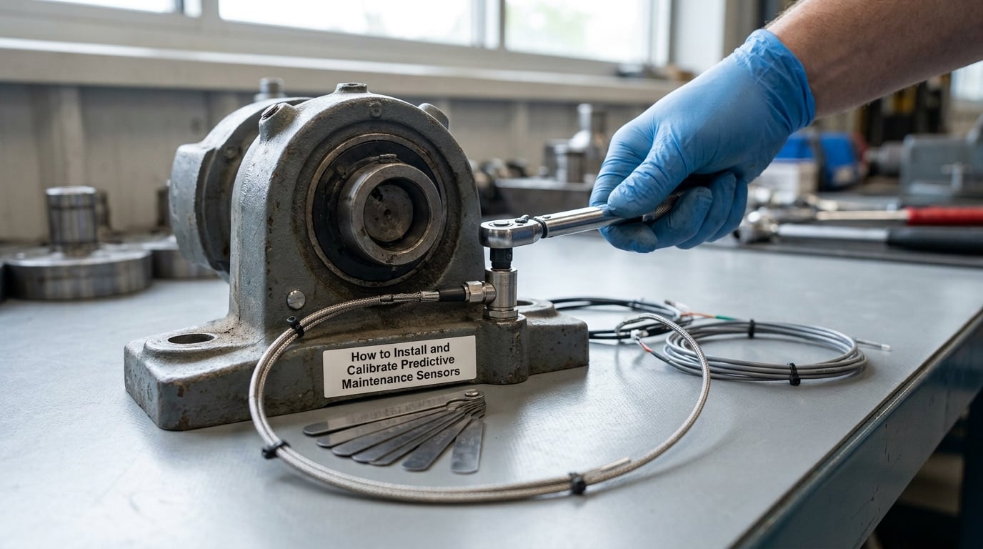
Follow this order and the install usually goes in without drama. The mistakes happen when teams skip steps 3 and 4 because the readings look fine on day one.
- Identify the asset and its criticality. Record make, model, serial, speed, bearing arrangement, and location. A sensor with no asset record behind it generates data nobody can interpret later.
- Place the sensor on the load zone. For a motor, the drive-end and non-drive-end bearing housings. For a gearbox, the input and output bearings. Mount on rigid structure, not on sheet metal covers or painted brackets, and decouple the sensor from any cable by routing it loosely.
- Capture a baseline under normal load. Run the machine through its real production range for long enough to see several cycles, ideally several days. Record the operating condition alongside every reading, because a threshold set against a lightly loaded baseline will alarm all day under full production.
- Set thresholds, not guesses. Use ISO 10816 or ISO 7919 zones for machines in that class, or statistical limits from your own baseline. A common starting target is to get the false-positive rate under roughly one alert per asset per month, then tighten from there.
- Test the alert path end to end. Trigger a test alarm and confirm it reaches the right person and produces a work order. An alert nobody received is an untested feature.
- Document the install. Photograph the mounting point, record orientation and axis, note torque on a threaded stud, and store the calibration certificate. Whoever touches this asset in year three will need all of it.
- Recalibrate on a schedule. Vibration pickups need periodic calibration checks, typically annually or with the route. Temperature probes need verification against a known reference. Wireless units need battery and enclosure checks in the same visit.
How to Connect Sensors to a Condition-Monitoring Platform
The data path usually looks like this: sensor, transmitter, gateway, platform, work management system, and finally the technician holding a phone.
At the transmitter layer, older wired instruments speak Modbus TCP or RS-485 and hand off through an edge gateway. Newer systems publish over MQTT, which is why MQTT and OPC-UA show up in nearly every integration conversation: OPC-UA for structured industrial data, MQTT for lightweight publish-subscribe messaging to cloud and analytics services.
Four things have to be right, or the platform quietly lies to you:
- Tag and timestamp integrity. Every reading carries the asset ID, sensor ID, measurement type, engineering units, and a timestamp from the same clock across the system. Drift between sensor clocks makes trend comparisons useless.
- Normalization. Scale factors and units convert a raw count into g or mm/s RMS, C or F, bar or psi. Do this once at the gateway, not in every downstream report.
- Load condition context. Ideally the platform knows machine speed or production state, so a reading at 40 percent load is not judged against a baseline captured at full load.
- Alarm ownership. Every alert has a named owner, an acknowledgement requirement, and an escalation path. This is the difference between a monitoring program and an email graveyard.
Network reliability deserves its own attention. Wireless needs a radio survey before you commit: walk the plant with a meter, check dead zones behind cabinets and inside enclosures, and place gateways so no sensor sits at the edge of coverage. Segment the monitoring network from production controls, require unique device credentials, and encrypt what leaves the site.
How to Turn Sensor Alerts into Maintenance Actions
An alert that does not change what anyone does on Monday morning is just noise. The design principle is that each alert type carries a matching response, agreed in advance.
- Urgent alert, a hard threshold breach on a critical asset: stop the machine and check now. These should be rare enough that people act on them without hesitation.
- Planning alert, a trend crossing a maintenance window: raise a work order with a shutdown slot in the next planned outage, plus the parts list and the estimated labor.
- Watch alert, a small deviation: log it, add a follow-up inspection task, and let the trend decide. Most alerts belong here.
- Diagnostic alert, a specific fault signature: attach the fault type, the reading, the trend, and a recommended action from the vendor or your own procedure.
Then close the loop. After the repair, confirm the reading returned to baseline. If it did not, either the repair was incomplete or the fault has a second source, and either way the historian is now more valuable than the alert was.
Track a few numbers so the program can be judged on evidence: false-positive rate, MTBF on monitored assets, MTTR, OEE contribution, and how many unplanned callouts you converted into planned windows. Report those monthly and the skeptics get quieter on their own.
Common Mistakes and Troubleshooting
Almost every failed rollout traces back to one of these. They are worth naming plainly.
Poor sensor placement
Mounting on a bracket, a cover plate, or a nearby frame picks up structure noise instead of the bearing signal. Move the sensor to the rigid housing, in the load zone, aligned with the axis you want to read.
An unstable baseline
Thresholds learned over one shift, one load, or one season produce constant false alarms. Recapture the baseline across real production conditions, and freeze threshold tuning until you have a few weeks of clean data.
Alert fatigue
Ten alerts a day on one pump trains the crew to ignore the channel. Start with generous thresholds, review every alert for a month, classify what was real versus noise, and tighten only what you have evidence for. Practicing engineers on industry forums describe alert fatigue as the fastest way to destroy technician trust in a program.
Loose mounts and knocked-off sensors
Cleaning cycles, chip conveyors, and routine rigging knock sensors loose, and a magnet mount lets go quietly. Include mount inspection in the route, check indicator LEDs or signal presence remotely, and treat a silent sensor as a failed sensor.
Electrical interference
Poor shielding, cable runs next to variable frequency drives, and unterminated loops produce phantom spikes. Route cables away from drives and motors, use shielded twisted pair, and verify ground continuity.
Dirty or fouled readings
Thermography lenses, ultrasonic microphones, and oil probes degrade fast around dust, mist, and swarf. Clean them on a schedule and record readings with the condition noted.
Neglected calibration and battery logistics
Drift accumulates quietly. Put recalibration and battery replacement on the same calendar as lubrication, or a six-month program becomes a twelve-month program and then stops.
Alerts with no assigned action
This is the most common failure of all, and it is a process problem, not a sensor problem. If nobody owns the alert, nothing changes. If nobody closes the loop, the data slowly stops being trusted.
One more honest limitation: predictive maintenance does not replace preventive or safety inspection. Lubrication, guarding, safety devices, and statutory checks stay on their schedules regardless of what the sensors say.
Frequently Asked Questions
What are predictive maintenance sensors for factory equipment?
They are vibration, temperature, oil-condition, acoustic, pressure, current, and position devices mounted on motors, pumps, gearboxes, compressors, conveyors, and chillers. They continuously measure a physical signal that changes as the asset degrades, so a maintenance team can schedule a repair from real condition data instead of a fixed calendar interval. Most plants start with vibration and temperature on rotating equipment.
Do older machines need to be replaced to use predictive maintenance sensors?
Usually not. Most sensors mount on existing bearing housings, motor frames, terminal boxes, and pipework without drilling or removing the machine. Retrofitting is harder where there is no machined flat surface, where the housing is cramped, or where existing instrumentation already occupies the space. Adhesive and magnetic mounts exist for those cases but give poorer vibration coupling, so plan a light machining operation where accuracy matters.
Are wireless sensors reliable enough for critical factory equipment?
For most rotating equipment, yes, provided the radio network is surveyed first. Wireless units are standard for trend monitoring where a missing sample is not a problem. Continuous trip-grade protection on safety-critical machines usually stays wired, because a loop failure is detectable and a missed radio packet may not be. Many plants run hybrid systems: wireless for the broad fleet, wired for the handful of critical assets.
How often should predictive maintenance sensors be calibrated?
Vibration accelerometers are typically verified annually and calibrated on a two to three year cycle, or whenever a reading looks questionable. Temperature probes should be checked against a known reference every six to twelve months. Wireless sensors need battery and enclosure checks on the same visit, usually annually. Treat calibration as part of the lubrication route so it actually gets scheduled.
How do manufacturers calculate predictive maintenance ROI?
The calculation compares the cost of the program, including sensors, gateways, software, installation labor, and calibration time, against the avoidable cost of unplanned downtime: lost production hours, expedited parts premiums, and extra labor hours for emergency repairs. A defensible approach tracks a before-and-after period on the same assets and reports converted unplanned callouts, MTBF, and MTTR rather than percentage savings claims.
Conclusion
Pick one critical asset and one failure mode. Mount the sensor that carries that signal, capture a baseline through real production load, set a threshold you can live with, and validate the first alert against your own maintenance history before you buy a single thing beyond that.
That sequence is cheap, fast, and it tells you more about whether the program will work in your plant than any vendor demonstration. Last reviewed for 2026.