
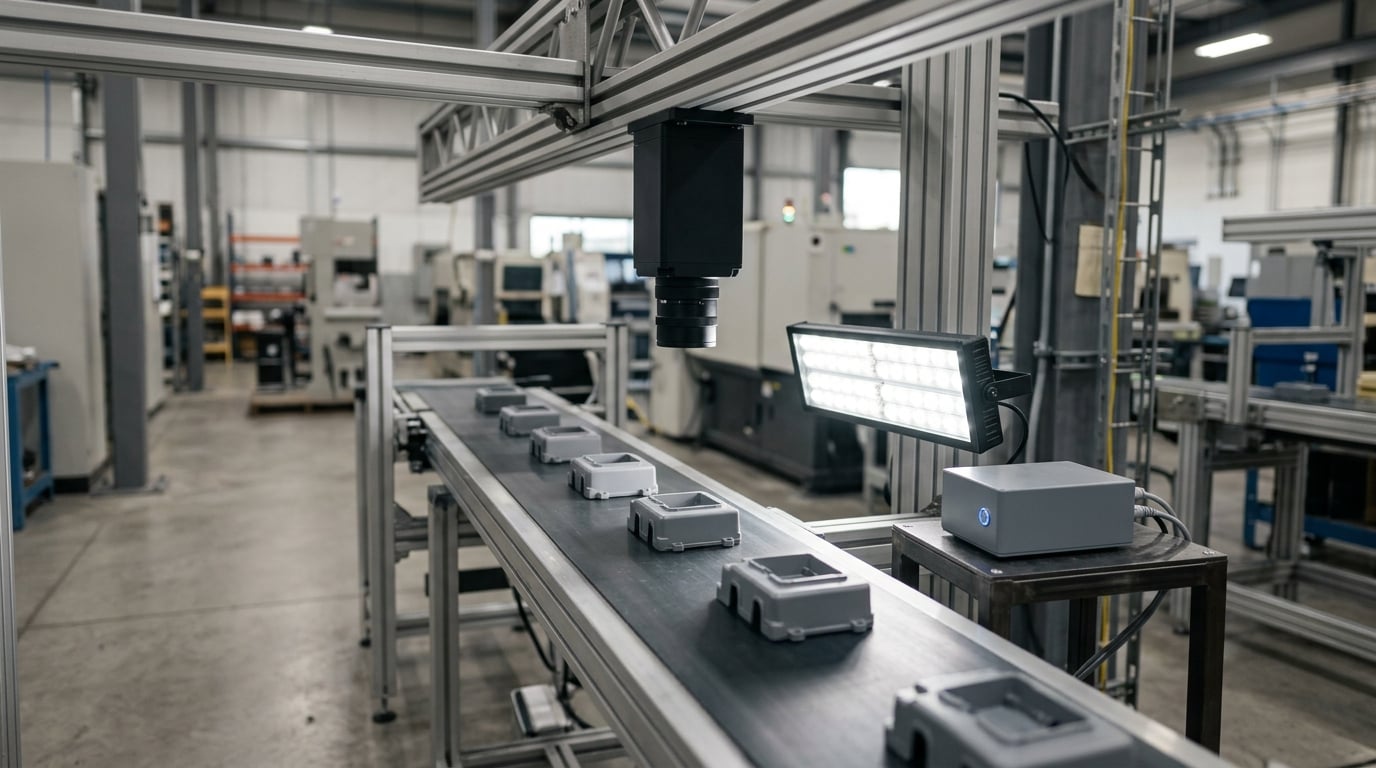
A machine vision inspection system is an automated quality control setup that uses industrial cameras, optics and lighting, plus image processing software, to examine each product and detect defects or measure dimensions without human eyes, then accepts, sorts or rejects every item in real time.
That short definition is the whole idea. What separates a useful system from a camera pointed at a belt is everything around the camera: controlled lighting, consistent part presentation, a trigger that fires at the right instant, software tuned to the specific defects you care about, and a reject path that removes bad parts before they reach a customer. This guide walks through how machine vision inspection systems work, what the components do, and how to scope a project without buying hardware you do not need.
One thing worth saying up front: most of the difficulty in industrial inspection is not the algorithm. It is presentation and lighting. Practitioners in the machine vision community describe lighting as the hardest and least understood variable in the cell, and motion blur from a mistimed trigger as the most common physical problem. Budget your attention accordingly.
Table of Contents
- What Are Machine Vision Inspection Systems?
- How Machine Vision Inspection Systems Work
- What Components Make Up a Vision Inspection System?
- How Does Lighting Affect Inspection Accuracy?
- What Defects Can Machine Vision Detect in Manufacturing?
- Rule-Based, Learning-Based, and Hybrid Machine Vision
- How to Choose a Machine Vision Inspection System
- How Are Vision Systems Integrated with Production Lines?
- How Accurate Should a Machine Vision Inspection System Be?
- How Much Do Machine Vision Inspection Systems Cost?
- What Are the Common Failure Modes?
- Frequently Asked Questions
- What are machine vision inspection systems and how are they used?
- How do vision inspection systems work?
- What are the different types of visual inspection methods?
- Do machine vision systems replace human inspectors?
- How accurate is machine vision inspection?
- How long does machine vision system commissioning take?
- Conclusion
What Are Machine Vision Inspection Systems?
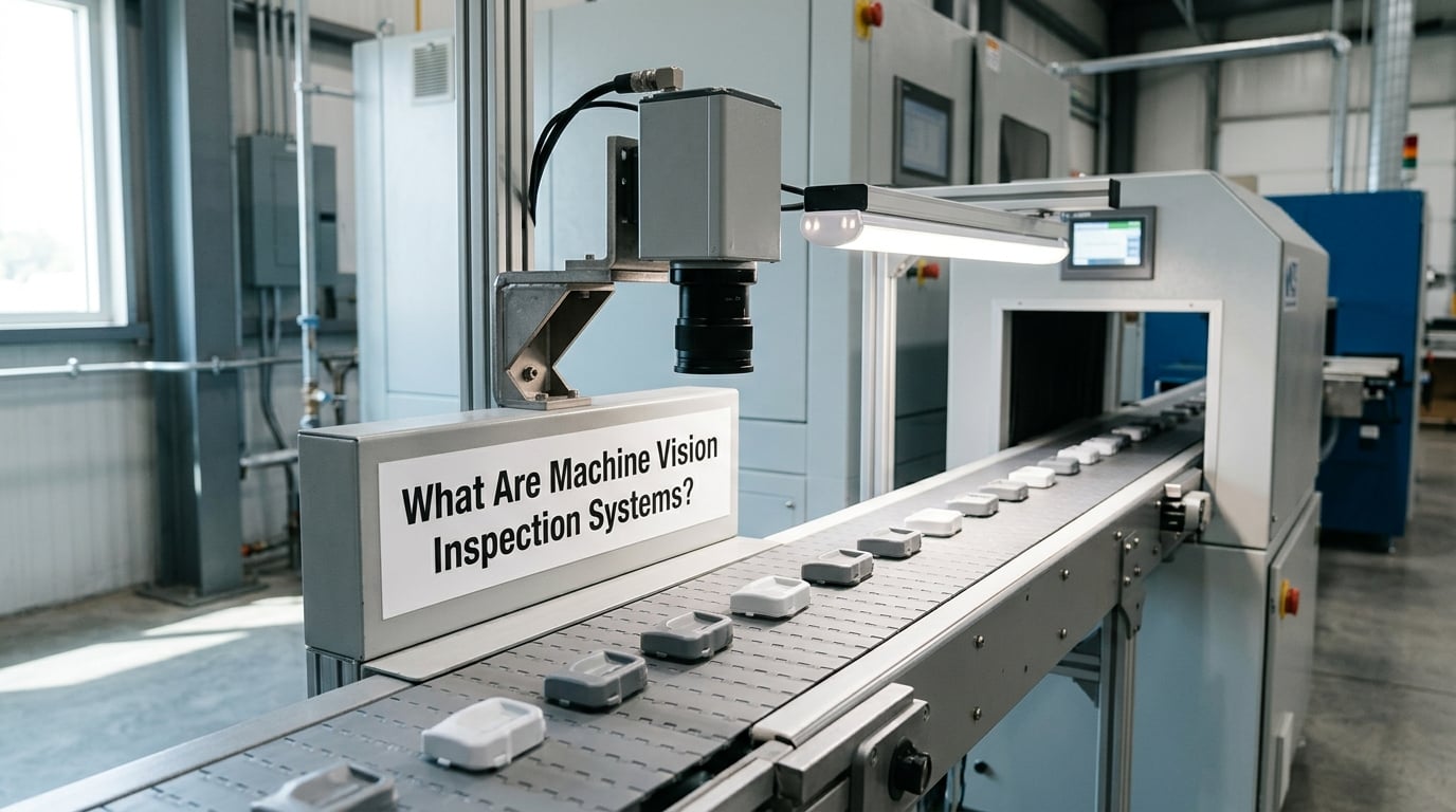
Machine vision inspection systems are automated setups that use cameras, controlled illumination and computer vision software to check products for defects, verify assembly, read labels and take measurements, and then act on the result without an operator making the call. They are used for inline inspection on a running line and for offline inspection at a station, and they are non-contact, so nothing touches the part.
The practical difference from a person with a loupe is consistency and coverage. A trained inspector checks a handful of parts a minute, and fatigue sets in after an hour. Vision checks every part at line speed with the same tolerance every time, and it stores the evidence. That is why automated visual inspection tends to land on high-mix, high-volume lines where a missed defect is expensive: molded plastic housings with cosmetic flow marks, machined metal components checked for diameter and concentricity, printed cartons checked for label presence and print contrast, blister packs checked for a missing tablet.
What a system commonly catches:
- Surface defects such as scratches, stains, weld spatter, flow lines and contamination
- Dimensional errors measured in millimeters, including hole position, width, height and concentricity
- Assembly problems such as a missing fastener, an unseated connector or a part installed backwards
- Label and print errors, including missing labels, wrong dates, blurred codes and unread barcodes
- Presence or absence checks for caps, seals, inserts, fluid levels and fill quantities
A system is different from plain camera-based monitoring, which records video for later review and does not make a decision. Monitoring tells you what happened. Inspection tells you pass or fail while the part is still on the belt, and that decision usually goes straight to a reject mechanism, a PLC, or both.
How Machine Vision Inspection Systems Work
The workflow is the same on every system, whether the brain is a smart camera running a dozen tools or a PC with a GPU running a neural network. Five stages, running over and over, once per part or once per image line.
1. Present and trigger
A sensor detects the part. That could be a photoelectric sensor upstream, an encoder tracking belt position, or a robot placing the part in a fixture. The trigger tells the camera when to expose. Trigger accuracy matters more than most buyers expect: mistiming is what produces motion blur.
2. Capture the image
The camera exposes under a light source chosen for the defect you are hunting. Exposure time must be short enough to freeze the part. A strobed light helps here, because it delivers very short, very intense illumination rather than a long dim one.
3. Preprocess
Raw sensor data is messy. Software removes noise, corrects brightness and lens distortion, flattens uneven lighting, and normalizes contrast so the next stage sees a consistent image every time. Skipping this step is one of the top reasons a system works on the bench and fails on the line.
4. Analyze
Algorithms compare the image against quality criteria. Rule-based tools do this with geometry and thresholds: find the edge, measure from a calibration target, check that the distance falls inside a tolerance window. Learning-based tools train a convolutional neural network on labelled images of good and bad parts and let it classify what it sees.
5. Decide, reject, record
The result becomes a pass or fail, sometimes with severity classes. The system signals the line controller, a diverter pushes the part into a reject bin, and the image plus measurement data get stored against the part serial number for traceability and SPC.
Takt time is the term for the total time one full inspection cycle is allowed to consume. If your line runs 40 parts per minute, the budget is 1.5 seconds per part, and every stage above must fit inside that including the reject motion. Sizing a system against takt time rather than against a demo speed is the difference between a cell that works and a cell that bottlenecks the line.
Spatial resolution is simply field of view divided by pixels across. A 2 megapixel camera covering a 100 mm field of view puts about 1440 pixels across that 100 mm, which works out to about 0.07 mm per pixel. Size the field of view to the smallest area that still contains the features you must measure, because every extra millimeter of field of view makes each pixel cover more real material.
What Components Make Up a Vision Inspection System?
A vision system is a chain, and the weakest link sets the accuracy. Selection criteria for each part:
- Camera. Resolution sets the detail you can resolve, frame rate must exceed your takt requirement, and the interface has to survive the plant environment. Monochrome sensors are more sensitive and usually the right choice when color is not part of the inspection.
- Optics. Field of view, working distance, focal length and depth of field. A cheap lens with distortion that shifts after a bump will cost more in scrapped parts than it saved at purchase.
- Lighting. The most important component and the most underestimated one. Matched to surface finish and defect type, as covered below.
- Triggers and encoders. Photoelectric sensors, rotary encoders or timing belts that tell the vision system exactly where each part is. Hardware timing beats software timing on fast lines.
- Processing hardware. Either a smart camera with everything embedded, or a camera feeding a frame grabber and an industrial PC. Processing capacity has to fit the cycle time with headroom for the worst part, not the average one.
- Vision software. Rule-based tools, a trained model, or both. Commercial platforms give support and a large tool library; in-house stacks built on open libraries cost less and demand more engineering.
- Human-machine interface. What the operator sees: pass or fail, defect type, measurement values, rejected images, and a way to acknowledge an error.
- Reject mechanism. Air blast, mechanical pusher or swing arm. It must finish its move inside the takt time and place parts in the right bin.
- Data systems. Image archiving, measurement logs, export to MES or ERP, and statistical process control. Decide up front how long images are kept, because storage planning is a line item people forget.
How Does Lighting Affect Inspection Accuracy?
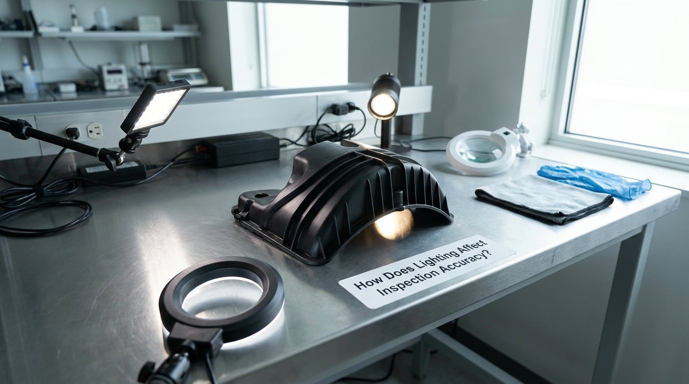
Lighting decides which defects exist in the image. A scratch on a matte black housing may be invisible under diffuse dome light and obvious under grazing side light. Choose the technique from the defect physics, not from a catalog habit.
| Technique | What it does | Best for |
|---|---|---|
| Diffuse dome | Even, shadow-free light from all directions | Color and cosmetic appearance on curved surfaces |
| Coaxial | Light along the camera axis | Flat, specular surfaces and scratch detection |
| Ring | Uniform annulus around the lens | Illuminating small parts and reducing reflections |
| Backlight | Silhouettes the part against a bright background | Presence or absence, outline and dimensional profile |
| Dark field | Light at an angle so only surface texture reflects into the lens | Fine surface texture, hair, dust and contamination |
| Structured | A fixed pattern projected onto the part | Height, warpage, 3D profile and gap measurement |
Two rules cover most cases. Glossy and polished surfaces need diffuse or coaxial light to kill glare. Matte, textured or slightly curved surfaces benefit from directional light, because the shadow created at a defect boundary is what the algorithm measures.
What Defects Can Machine Vision Detect in Manufacturing?
Defects fall into a handful of families, and each family has a natural measurement approach.
- Dimensional. Hole diameter, part width, hole position, concentricity, roundness, flatness. Measured by edge detection against a calibrated scale, so lighting and calibration drive accuracy more than camera resolution does.
- Cosmetic. Scratches, dents, flow marks, sink marks, stains, orange peel, weld spatter. Mostly a surface-contrast problem, which makes it the hardest family for rule-based tools.
- Assembly. Missing or extra components, wrong part installed, fasteners not torqued to a visible depth, connectors not seated. Often checked with template matching or presence or absence logic.
- Labeling and print. Label present, print contrast, character legibility, best-before code, barcode grade. Text and code verification is a mature, fast application.
- Presence or absence. Caps, seals, inserts, fluid level, fill quantity, tamper seal. The simplest and most reliable category, since the decision is binary and the setup is forgiving.
- Surface and contamination. Dust, hair, fingerprints, residue, particles on food or pharmaceutical surfaces. Typically handled with dark-field or hyperspectral illumination.
By industry: automotive and metalworking lean on dimensional and assembly checks, electronics and semiconductor on presence and defect detection on boards, food and beverage on label and packaging verification, pharmaceuticals on blister completeness and vial fill levels, and web or roll material producers on continuous surface inspection with line-scan cameras.
Rule-Based, Learning-Based, and Hybrid Machine Vision
Rule-based systems measure. Learning-based systems classify. Hybrid systems do both, and most mature installations are hybrid.
| Rule-based image processing | Learning-based defect detection | |
|---|---|---|
| How it decides | Geometry, thresholds and fixed tool logic | Neural network trained on labelled images |
| Training data | None, plus a calibration target | Labelled good and bad parts, often hundreds or thousands |
| Best at | Dimensions, position, presence, code reading | Cosmetic and textured surface defects, high variation |
| Explainability | High, every measurement is traceable | Lower, needs validation to be trusted |
| Speed | Very fast, milliseconds | Depends on model size and hardware |
| Failure mode | Fails when part geometry changes | Fails quietly on defect types it never saw |
Pick rule-based when the defect has a measurable shape and a tolerance. Pick learning-based when the defect is a vague variation in appearance and written rules would take forever to tune. Validation matters more for learning-based systems: run a challenge set of known good and known bad parts, and hold out samples the model never saw, because a model tested on its own training data tells you nothing.
How to Choose a Machine Vision Inspection System
Before talking to an integrator, work through this checklist. It is the shortest route to a system that survives contact with production.
- Write down the defect list. Every defect you intend to catch, with its size and location on the part. A system cannot be specified against the phrase cosmetic defects.
- Set the smallest feature you must detect. Then compute required pixel resolution from the field of view and camera resolution, and confirm it against your hardest tolerance rather than your easiest.
- Fix the throughput number. Parts per minute, and the cycle budget in seconds per part that follows from it. Every component has to fit inside that budget.
- Quantify part variability. Colour range, gloss, warp, tolerance stack, incoming supplier variation. Variability is the main driver of both false rejects and commissioning time.
- Decide how you will present the part. Fixtures, nesting, orientation, index positions. Presentation decides repeatability more than optics do.
- Set acceptance criteria. Target false accept and false reject rates, written down as numbers the quality team will sign off on. Most disputes trace back to criteria nobody agreed in advance.
- Plan calibration. A calibration target checked at start of shift, plus what happens when a check fails.
- Define the environment. Vibration, washdown, dust, ambient light, temperature swings, oil mist. These drive enclosure and connector choices.
- Budget maintenance. Lens cleaning intervals, lighting degradation, target replacement and the skill needed on shift to clear a fault.
- Calculate total cost of ownership. Hardware, integration, software licences, training, and the floor space and labor you reclaim, counted over several years rather than at purchase.
How Are Vision Systems Integrated with Production Lines?
Integration is where projects stall, because a vision cell is a control system, not a camera on a stand. Encoder or sensor signals drive the trigger, the camera sends results to a PLC or robot controller, and the PLC drives the reject device. Handshaking, timeout behaviour and fail-safe states have to be defined before commissioning, not after.
Inspection sequencing also needs a decision. Inspect in-line before the part is packaged, or verify the finished pack after it is closed. Secondary packaging checks catch label and code errors that part-level inspection cannot see, at the cost of a second station.
Data flow deserves its own paragraph. Measurements should land somewhere durable, not only on a local drive. Linking results to a part serial number gives you traceability for recalls, and stable measurement data feeds statistical process control, where capability indices such as Cp and Cpk tell you whether the process itself can hold the tolerance. Without logging, a vision system is just a reject machine and you lose most of the reason you bought it.
How Accurate Should a Machine Vision Inspection System Be?
Accuracy should be stated as three separate numbers, because they behave differently.
- Resolution. The real-world size one pixel covers, set by field of view divided by pixels across. A common sizing rule is that the tightest tolerance should span at least five pixels, with more if possible.
- Repeatability. How close repeated measurements of the same part are. Good systems land in a few thousandths of a millimeter on well-presented parts.
- Reproducibility. How close the system agrees with itself across shifts, operators and calibration cycles. A gauge study across operators and machines is the honest way to measure it.
Sub-pixel edge detection improves resolution further, by fitting the intensity gradient across several pixels to locate an edge to a fraction of a pixel. That matters when the tolerance is tight relative to the pixel grid.
The practical ceiling is usually not resolution. It is the false accept and false reject trade. A false negative lets a bad part ship. A false reject stops a good part and, if operators lose trust, they start ignoring the reject light, which quietly turns your inspection into decoration. Most production cells end up trading a small false accept rate against a low false reject rate, then sealing goods on the suspect side afterward. Write both targets down and validate against real samples before the line runs at speed.
How Much Do Machine Vision Inspection Systems Cost?
Figures below are typical U.S. ranges that vary by region, supplier and application, and they change over time. Treat them as planning bands, not quotes.
- Single-camera smart camera setup, camera, lens, basic lighting, controller and software: roughly low five figures of US dollars installed.
- PC-based cell with frame grabber, industrial PC, fixtures, encoder, reject and integration: mid five figures to low six figures.
- Multi-station or 100 percent inspection line with several cameras, data archiving and MES integration: six figures and up.
- Learning-based inspection adds model development, labelled defect samples and often hardware for inference, plus the ongoing work of retraining.
- Running cost is usually under a tenth of purchase price per year for optics and lighting upkeep, with software licences and support as the line that grows.
What drives the final number is defect difficulty, defect size, cycle time, how much integration the line needs, and how much data the customer wants kept. A presence or absence check on a capped bottle is a far simpler project than 100 percent surface inspection of a textured molded part.
What Are the Common Failure Modes?
Most complaints about vision come from a short list of physical causes, and all of them have fixes.
- Motion blur. Exposure too long for the part speed. Fix by shortening exposure, strobing the light, or synchronising shutter timing to the motion source, which is the standard answer among experienced integrators.
- Glare and reflections. Specular parts reflect the light source into the lens. Fix by changing light geometry, polarising, or darkening the surrounding area.
- Part presentation changes. Parts arrive rotated, nested or warped, so features land outside the region of interest. Fix with fixtures, guides and an orientation check before inspection.
- Vibration. Loose mounts shift calibration. Fix with rigid mounting and periodic checks.
- Calibration drift. The system slowly stops measuring correctly, often after a lens swap or a collision. Fix with automated calibration checks tied to the line schedule, and an alarm when a check fails.
- Background clutter. Conveyor texture, a neighbouring cell, or a dirty fixture becomes a feature the algorithm measures. Fix by masking the region of interest and keeping fixtures clean.
- Inadequate training data. A model trained on a few dozen parts performs badly on the variety the line actually produces. Fix by collecting real defect samples from production, not from a controlled trial.
- Line speed outrunning the cell. The system quietly drops parts or misses triggers at peak rate. Fix by sizing to peak takt, and test at peak, not at nominal.
One last expectation to set honestly: practitioners point to six to twelve months before a new vision system reaches stable, reliable detection on parts that vary the way real production parts vary. Anyone promising full production performance in a week is describing a demo, not a deployment.
Frequently Asked Questions
What are machine vision inspection systems and how are they used?
A machine vision inspection system is an automated quality control setup that uses industrial cameras, optics and controlled lighting with image processing software to inspect each product, detect defects, verify assembly, read labels or take measurements. It then accepts, sorts or rejects every item in real time, and logs the image and result for traceability, without a person making the call.
How do vision inspection systems work?
The process has five stages. A sensor triggers the camera at the right moment, the camera captures an image under purpose-chosen lighting, software preprocesses the image to remove noise and normalise contrast, an algorithm measures or classifies the features of interest, and the result becomes a pass or fail that drives a reject mechanism and a stored record. Everything must fit inside the takt time for the line.
What are the different types of visual inspection methods?
The main methods are manual visual inspection by a trained operator, automated visual inspection using standard machine vision, automated optical inspection for electronics boards and assemblies, and AI-assisted inspection where a trained model handles variable appearance. Manual inspection is flexible but slow and inconsistent. AVI is fast and repeatable on measurable defects. AOI suits board-level defect detection. AI-assisted inspection covers cosmetic and textured defects but needs validation.
Do machine vision systems replace human inspectors?
Usually they replace the repeat checking, not the role. Vision handles 100 percent coverage at line speed on measurable defects, while people handle problem solving, judgement calls on ambiguous parts, model retraining and line clearance. Plants that remove inspection staffing entirely tend to discover they still need skilled technicians to keep the system honest.
How accurate is machine vision inspection?
Accuracy depends less on camera megapixels than on resolution per defect, lighting, part presentation and calibration. A common rule is that your tightest tolerance should span at least five pixels, with sub-pixel edge detection improving on that. Repeatability on well-presented parts can reach a few thousandths of a millimeter. The real limit is usually false rejects caused by part variation, not measurement resolution.
How long does machine vision system commissioning take?
Expect weeks of tuning for a rule-based system and longer for learning-based ones, which need real defect samples collected from production. Practitioners commonly report six to twelve months before a new system reaches stable detection on variable parts. A large share of that timeline goes to presentation, lighting fixtures and data collection rather than to software configuration.
Conclusion
Start with the defect list and the smallest feature you have to catch. From there, compute the pixel resolution you need, set the cycle budget from your takt time, and only then choose a camera. Everything else in a machine vision inspection system, lighting, presentation, calibration, triggers, hangs off those three numbers.
Then test it on the parts that actually come off your line, including the ugly ones. A system that passes a controlled trial and struggles in production was never specified against the right problem, and that is the expensive way to find out.