
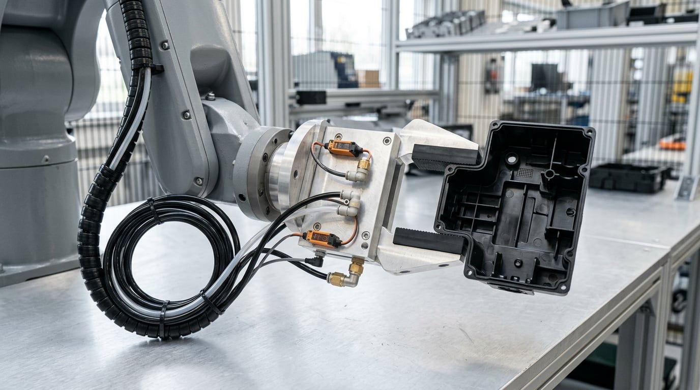
End of arm tooling design basics come down to three things: the part, the way it is presented, and the cycle it has to live in. Get those right first and the gripper choice, the sizing math and the safety review all fall into place. Get them wrong and you end up rebuilding a tool that was never going to hold cycle time. This guide is the working reference we use, refreshed for 2026, and it walks the whole job from requirements capture through to production sign-off.
The short version: end-of-arm tooling (EOAT) is any device bolted to the robot wrist flange that lets the arm grasp, move or process a workpiece. Grippers, vacuum cups, magnetic holders, welding torches, dispensing heads and inspection sensors all qualify. Most plastic molding cells run two or three of those families, and the design work is mostly about making sure the tool fits the robot’s real limits rather than its headline number.
Table of Contents
- What You Need for End of Arm Tooling Design Basics
- Step-by-Step End of Arm Tooling Design
- 1. Define the Part and Handling Task
- 2. Calculate Loads, Moments, and Safety Factors
- 3. Choose the End Effector Architecture
- 4. Design the Part-Presentation Interface
- 5. Select Materials and Components
- 6. Add Sensing, Alignment, and Failure Protection
- 7. Verify Fit, Safety, and Maintainability
- 8. Prototype and Validate in Production
- End of Arm Tooling Design Checklist
- Common Mistakes
- Frequently Asked Questions
- How do I choose the right gripper for a plastic part?
- What is the recommended safety factor for end-of-arm tooling?
- How do I calculate the required grip force for a part?
- Can one EOAT handle multiple part geometries?
- How should sensors be used to confirm that a part is picked?
- What should be tested before putting new EOAT into production?
- Conclusion: Start With the Part and Cycle
What You Need for End of Arm Tooling Design Basics
Design basics are cheap to do and expensive to skip. Before anyone picks a gripper, gather this set. A stack of real parts and a drawing with tolerances beats any catalog estimate.
- Part samples. At least a dozen, including the worst ones from the last production run: flash, warpage, short shots, sink marks, contamination. Runners and gates if the tool takes parts directly off the machine.
- Part drawing and material data. Wall thickness, stiffness, shrinkage, surface finish, brittleness, coefficient of friction, temperature at pickup, and any cosmetic surfaces that cannot be marked.
- Robot datasheet. Payload versus centre-of-gravity offset curve, allowable moment of inertia per axis, flange pattern and thread callout (commonly an ISO 9409-1 size such as 50-4-M6), joint speed limits, and the repeatability figure you are actually buying.
- Cell layout. Where the tool travels, what it clears, how close it gets to people and fixtures, and where the controller and I/O sit relative to the wrist.
- Cycle time target. Parts per hour required, and therefore available seconds per pick, transfer and place. Changeover frequency matters just as much, because a tool that takes forty minutes to strip is expensive even when it runs well.
- Environment. Ambient temperature, dust, oil mist, washdown or food-grade requirements, static sensitivity, and whether an operator reaches into the guarded space during a jam.
- Upstream and downstream data. How parts arrive (bulk, nested, in trays, on a conveyor), where they go, and what the downstream equipment expects to receive.
- Supplier data and hardware. Grip force curves, cup load ratings by surface, sensor datasheets, CAD software, a caliper set, a scale accurate to a few grams, and access to a prototype machine.
Step-by-Step End of Arm Tooling Design
Follow the steps in order. Each one has an acceptance test, and moving on before the current step passes is how tools end up being rebuilt during commissioning.
1. Define the Part and Handling Task
Write the handling specification before touching a CAD sketch. Every dimension that affects the tool belongs on it, including how much variation you have to tolerate.
| Parameter | What to record | Why it changes the design |
|---|---|---|
| Mass | Measured, not calculated, plus a tolerance band | Sets payload, grip force and inertia |
| Centre of gravity | Location relative to the grip point | Drives which wrist axis carries the moment |
| Geometry | Envelope, wall thickness, ribs, draft, bosses | Decides jaw spacing and finger shape |
| Surface condition | Texture, gloss, dust, oil, mold release residue | Decides elastomer pad and vacuum cup choice |
| Damage limits | Allowed scuffing, load, cosmetic surfaces | Limits contact force and pad hardness |
| Orientation | Fixed, random or known from vision | Decides whether a nest or a fixture is needed |
| Presentation | Bulk, nested, tray, chute, conveyor | Decides the pickup strategy |
| Takt | Seconds available per part | Limits stroke, acceleration and settle time |
Acceptance test: an operator who has never seen the cell can read the sheet and describe where the part sits, how it is picked, and what happens if it is not there.
2. Calculate Loads, Moments, and Safety Factors
Payload, gravity moment and inertia are three independent limits. A tool can pass one and fail the other two, and the symptom of exceeding inertia is not an alarm. It is drifting accuracy, vibration and premature gearbox wear.
Static gravity moment about the flange is simple: M = m x g x r, where m is total carried mass in kg, g is 9.81 m/s squared, and r is the centre-of-gravity offset from the flange face in metres. Combine the part and the tool before you compute it.
Inertia about each wrist axis comes from your CAD mass properties, corrected for the offset of each element from that axis using the parallel axis theorem. The point-mass shortcut, m x r squared, is a lower bound for a long gripper body or a large flat panel, and the gap grows as mass concentrates near the axis. Model the gripper as a solid and use the sum of m x r squared only for a first cut.
Shock and emergency-stop cases are where tools get designed out of tolerance. Emergency-stop deceleration of several times normal operating acceleration produces a transient torque far above anything in the trapezoidal motion profile, and it is routinely the governing case for tool stiffness and grip security.
A worked example. A four-finger gripper body of 4.2 kg holds a 0.35 kg housing whose own centre of gravity sits 0.12 m from the flange, while the tool centre of gravity sits 0.19 m out:
| Quantity | Calculation | Result |
|---|---|---|
| Total carried mass | 4.2 + 0.35 | 4.55 kg |
| Combined CoG offset | (4.2 x 0.19 + 0.35 x 0.12) / 4.55 | 0.185 m |
| Static gravity moment | 4.55 x 9.81 x 0.185 | 8.26 N x m |
| Point-mass inertia, lower bound | 4.2 x 0.185 squared + 0.35 x 0.185 squared | 0.156 kg x m2 |
| CAD solid inertia for the tool | Model, do not estimate | Verify at commissioning |
Treat those numbers as illustrative. The value you can act on comes from your robot’s payload-versus-offset curve at 0.185 m, its allowable inertia per axis, and your own CAD mass model. Keep a 10 to 20 percent margin on mass and offset. That margin exists for the fasteners, washers, connectors and sealant that CAD mass properties leave out, which routinely add 5 to 15 percent to a compact tool and can flip a marginal verdict.
Grip force is the other half of the same calculation. The force each finger needs is the part weight plus inertial load, divided by the friction coefficient and the number of contact points, then multiplied by a safety factor:
F per finger = (m x (g + a)) / (mu x n) x SF
With a 0.35 kg part, 6 m/s squared acceleration, mu of 0.6, two contact points and a safety factor of two, that works out to about 9.2 N of grip force. Choosing a gripper rated well above that number is normal, because the safety factor covers part variability, wear, contamination and the emergency-stop transient all at once. For vacuum, the equivalent rule is a vacuum safety factor of 2 or more against rated cup load, with leak-off considered separately.
Acceptance test: the tool clears every limit on the robot datasheet at your planned offset, with margin, and the check summary is written down with the supplier figures substituted for the placeholders.
3. Choose the End Effector Architecture
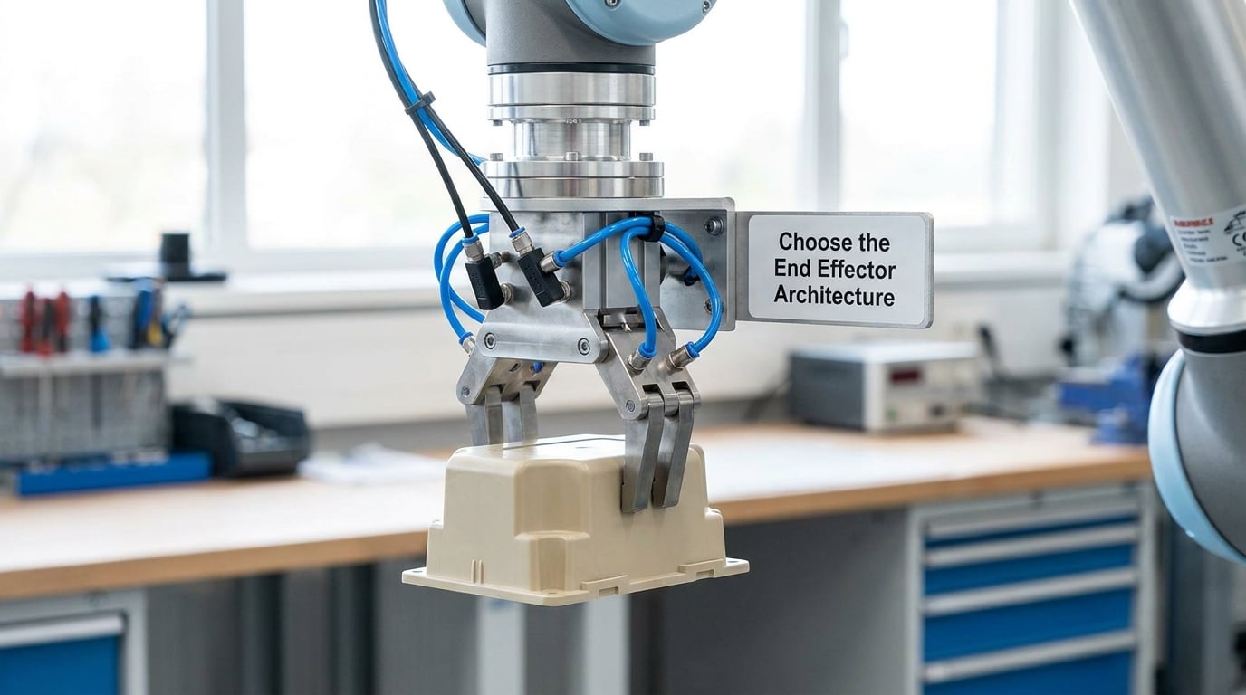
Pick the gripping concept from the part, not from what the integrator has in the van. Then pick the actuation from the concept.
| Family | Best for | Key selection inputs | Main watch-out |
|---|---|---|---|
| Two-finger parallel | Rigid, boxy molded parts with flat faces | Opening range, grip force, stroke, footprint | Needs two parallel surfaces and a known orientation |
| Three or four finger | Round parts, tubes, irregular bodies, machine tending | Envelope, centering behavior, part protrusion | More mass, more links, more ways to bind |
| Vacuum cup array | Flat or curved panels, thin-wall housings, bagged parts | Surface material, texture, orientation, leak rate | Fails on textured or dusty surfaces without a purge |
| Needle or internal | Sealed containers, hollow parts, no external grip | Port access, insertion depth, sterilization | No positive location; hard to verify grip |
| Magnetic | Ferrous steel parts only | Material grade, wall thickness, surface roughness | Useless on aluminum, plastic or stainless |
| Soft or custom finger | Fragile, thin-wall or cosmetic parts | Pad hardness, contact area, allowable force | Degrades and changes the effective grip force |
Actuation follows. Pneumatic is fast, stiff, cheap and needs a service unit plus a valve manifold, which adds mass at the wrist. Electric is cleaner, has holding power when air fails, and adds a drive to the wrist. Hydraulic belongs on heavy or high-force work and rarely suits molding cells. Many production cells run a hybrid, for example vacuum for a presentation pick and a powered jaw set for the place into the mold.
Where you can, move the valve manifold, vacuum generator, regulator and vision controller to the base or the cell cabinet and keep only flexible services at the wrist. It is the cheapest mass reduction available.
Acceptance test: you can name the gripping concept, the actuation, the actuator source, and the fail state when power or air is lost, in one sentence each.
4. Design the Part-Presentation Interface
A perfect gripper fails if the part is never presented the same way twice. Presentation design usually decides the cell’s success rate more than the gripper does.
Nested parts on the sprue and runner need a pick plate that engages one part at a time and a shear action that separates it without flash. Bulk parts in a hopper want a chute or flexible feeder that meters one part into a known pose. Trays want a locating nest with a positive stop, or a vision correction if the nest tolerance is loose. Conveyed parts want a stop or escapement so the pickup pose is repeatable.
Locating features should be few, generous and located from the part’s own datums. Datum pins should be diamond or relieved so a slightly out-of-size part cannot bind. Add a hard stop the part rests against, and make the pickup position visually obvious from the operator side.
Common presentation errors show up in this order of frequency: parts presented with the grip axis rotated randomly, nest pockets dimensioned to nominal rather than worst case, chutes that jam on flash, and no clearance for the fingers themselves to enter the nest. Check finger clearance against the full sweep of the jaw stroke, not the closed position.
Acceptance test: fifty consecutive pickups with no manual touch and no failed presentation.
5. Select Materials and Components
Material selection is where end of arm tooling design basics turn into real mass and stiffness numbers. Put the stiff material near the flange and the light material at the tip.
| Material | Typical role | What to watch |
|---|---|---|
| Aluminum 6061 plate | Flange adapter and tool plate | Default choice; easy to machine, stiff for its weight |
| Hardened steel | Jaws, wear strips, guides | Heavier; only where wear demands it |
| Stainless steel | Wet, washdown or food-contact areas | Galling on threads; plan for it |
| Engineering polymers (acetal, PEI, PEEK) | Fingers, nests, guides, cable guides | More compliant than metal; check creep and heat |
| Composite or printed structure | Long fingers, low-mass panels | Check orientation, layer lines and moisture near hot molds |
| Elastomer pads (nitrile, silicone, urethane) | Part contact surfaces | Friction changes as it wears; make it replaceable |
Deflection sets placement. A long finger of one material carries far more load at the tip than a short one of a stiffer material, so the same grip force in a different shape produces a different placement error. Specify a maximum tip deflection and check the worst-case pick at the far end of the stroke.
Fasteners deserve the same attention as the plate. Use the specified socket head cap screws or dowel pins, torque them to the manufacturer figure with a calibrated tool, and fit thread-locking compound only where the design allows disassembly. Provide positive retention for anything that could detach during a collision, and leave access to every fastener for changeover.
For sensors, fittings and fluid components, match thread size to hose size rather than the other way around, and specify vacuum-rated fittings everywhere a leak would matter. Acceptance test: every fastener is on the drawing with a torque spec, and the mass budget includes the hardware.
6. Add Sensing, Alignment, and Failure Protection
Assume a missed grip eventually happens. The question is whether the robot notices before the part hits the floor or the mold.
Part-present sensing belongs at the pickup pose, using a diffuse photoelectric or capacitive sensor, or vision if parts arrive without a reliable nest. Grip confirmation is a separate check: a stroke or position switch that proves the fingers closed on something, a vacuum pressure switch set above the minimum holding level, or an analog distance sensor with a window. Do not treat the grip command as confirmation.
Alignment and collision protection come next. A force-torque sensor at the flange catches misaligned approaches, but it is expensive and soft, so many cells pair a stiffness budget with simple mechanical compliance instead. Dropped-part detection comes from the same confirmation signals plus a vacuum leak switch, and its safe response is defined in advance: stop the arm, hold position or retreat to a safe point, and flag the cycle for operator intervention rather than retrying blindly.
Position feedback on the actuator, a worn-pad or pad-life indicator, and a vacuum pressure switch with a setpoint margin of 20 percent above minimum all belong in the specification. Redundancy is cheap here. A single confirmation signal that silently fails turns into a robot that keeps running without a part.
Then handle the cables. Design the dress-out first, not last: a dress pack or energy chain must clear the full motion envelope, avoid torsion at the flange, and leave enough slack for every joint limit. Cable bundles add unmeasured effective mass and stiffness, and a dressed cable that resists motion undermines the inertia numbers you calculated. Clamp at the tool, never to the moving cable. Acceptance test: the safe response to every lost signal is written in the control logic and tested on the real cell.
7. Verify Fit, Safety, and Maintainability
Walk the tool through the cell before you cut metal. Reaches, interference and pinch points show up on paper, but only some show up on a machine.
Check reach against every programmed point, including the tool changer park position and any manual maintenance position. Check interference through the full joint range with the gripper both open and closed. Identify pinch points between the gripper and the part, the fixture or the cell structure, and guard or block them rather than relying on a warning label. Confirm the tool cannot enter a hazardous machine opening with a part still held.
Confirm electrical and pneumatic safety: correct protection on the tool’s supply, isolation for maintenance access, and grounding of any metal structure that could carry a fault. Confirm fasteners have retention and torque marks. Confirm the changeover does not require reaching into a live hazard zone, and that an operator can swap fingers or cups with the tools a maintenance tech actually has.
Cleaning drives maintenance design. Molding cells deal with dust, release residue and oil. Smooth surfaces, no open pockets, and a pad and cup layout that wipes clean from one side keep downtime low. Mark the inspection points: pad thickness, cup wear, sensor alignment, cable condition, and the fasteners that loosen in vibration. Set intervals by cycle count, not by calendar.
Acceptance test: a maintenance tech completes a pad change and a sensor swap in under ten minutes with the cell locked out, without removing the tool from the robot.
8. Prototype and Validate in Production
A production cell proves out what a bench test cannot. Run the sequence in this order and do not skip to the fast version.
Weigh the finished assembly. Then re-run the combined centre of gravity and inertia math with measured values, including fasteners and hoses. Estimates change verdicts, and it is cheaper to find out on the bench. Compare against the robot datasheet and re-verify the mount and the payload-versus-offset curve.
Run a robot dry run at reduced speed with the tool powered but no parts, checking for interference through every joint limit. Then do low-speed commissioning with parts, logging joint current through the worst-case move. Sustained current near the limit means the tool is too heavy, too long, or too far out, and stepping speed and acceleration up gradually while watching current is a practical proxy for remaining torque headroom.
Measure cycle time against the takt target over a full run, including settle time and any vision cycle. Run capability trials on placement accuracy: at least a few hundred parts measured against the process window. Then test the failure modes deliberately. Remove a part and confirm the robot stops rather than moving on. Simulate a lost grip and confirm the response. Trigger the emergency stop mid-move and watch for a dropped part, a tool collision or a cable snag.
Set the sign-off conditions before the trials, in writing: placement capability, cycle time, failure-response behavior, and zero dropped parts during the failure-mode test. A tool that misses one of those goes back to the drawing board, not to production.
End of Arm Tooling Design Checklist
Run through this before the tool ships to the floor.
- Handling specification written and signed, including worst-case part variation.
- Mass, offset and inertia checked against the payload-versus-offset curve with 10 to 20 percent margin, and margins justified.
- Combined centre of gravity computed from every carried item, with hardware included.
- Grip force or vacuum load sized with a safety factor, including the emergency-stop case.
- Gripping concept and actuation chosen and documented with the fail state.
- Presentation method proven with 50 consecutive clean pickups.
- Tip deflection checked at the far end of the stroke and within limit.
- Every fastener specified, torqued, retained and accessible.
- Part-present and grip-confirm sensing installed, redundant where a miss is costly.
- Dress-out or energy chain clears the full motion envelope and is clamped at the tool.
- Pinch points guarded, tool cannot enter a hazard opening while holding a part.
- Cleaning method defined, wear points marked, inspection intervals set by cycle count.
- Assembled tool weighed and the math re-run with measured values.
- Low-speed commissioning logged, cycle time measured, capability study complete.
- Failure modes and emergency stop tested, with the written response verified.
- Spare fingers, pads, cups and sensors identified and stocked, with replacement time known.
Common Mistakes
These come up on almost every cell we look at, and each one has a practical correction.
Comparing the tool against the headline payload number. Payload is conditional on offset. A tool that fits the kilogram rating at the flange can exceed the limit at 300 mm out. Correct: work from the payload-versus-offset curve at your actual offset.
Trusting CAD mass properties. They exclude fasteners, connectors, sealant, hoses and dress pack, which add 5 to 15 percent on a compact tool. Correct: weigh the assembly and re-run the math.
Using point-mass inertia for a long tool. The shortcut is a lower bound, often 10 to 30 percent off for a long gripper body or a large panel, and the error grows as mass nears the axis. Correct: model the solid and add the parallel axis term.
Checking the wrong wrist axis. A laterally offset centre of gravity loads a different axis than most people assume. Correct: check all three wrist axes against the offset, not just the obvious one.
Ignoring inertia limits because torque passes. The symptom is not an error code. It is degraded accuracy, ringing, and gearbox wear you find six months later. Correct: treat payload, moment and inertia as three separate checks.
Adding dress pack and hoses after the mass budget is closed. A dressed cable adds effective mass and stiffness that the numbers never saw. Correct: include the routing in the model and clamp at the tool.
Commissioning at full speed. A marginal tool looks fine at reduced speed and reveals itself at production rates, with parts at risk. Correct: step speed and acceleration up gradually while logging joint current.
Treating the grip command as grip confirmation. A failed sensor or a part that slipped after pickup leaves the robot running with nothing in hand. Correct: a separate confirmation signal with a defined safe response.
Frequently Asked Questions
How do I choose the right gripper for a plastic part?
Choose from the geometry and the surface, not the robot. A part with two flat parallel faces suits a two-finger gripper; a round or irregular housing suits three or four fingers; a flat panel or thin-wall shell usually suits vacuum cups, provided the surface is clean and reasonably smooth. Then check opening range, grip force at your working stroke, and whether the fingers can enter your presentation nest. Add the part mass, the required safety factor and the changeover frequency before you commit.
What is the recommended safety factor for end-of-arm tooling?
Most integrators land between 1.5 and 2 on grip force and vacuum load, and keep a 10 to 20 percent margin on carried mass and centre-of-gravity offset against the robot datasheet. The force factors cover part variability, pad and cup wear, contamination and the emergency-stop transient. The mass margin covers what the CAD model leaves out, since fasteners, connectors and sealant routinely add 5 to 15 percent to a compact tool. Apply both, and document why.
How do I calculate the required grip force for a part?
Divide the part weight plus inertial load by the friction coefficient and the number of contact points, then apply a safety factor. Per finger, that is mass times gravity plus acceleration, divided by friction coefficient times contact count, multiplied by the safety factor. A 0.35 kg part at 6 m per second squared with a 0.6 friction coefficient, two contact points and a factor of two gives roughly 9.2 N per finger. Use the lowest friction coefficient the part will actually present, not the cleanest sample.
Can one EOAT handle multiple part geometries?
Yes, and it is often the right economic answer, but only if the variants share a common gripping feature such as identical boss spacing, a uniform flange or a consistent flat face. Swap fingers or use adjustable stops rather than rebuilding the whole tool. Watch the catch: changing fingers changes mass, offset and inertia, so re-run the centre-of-gravity and inertia checks for each configuration. If the variants differ in orientation or surface, a tool changer or two separate tools usually beats one compromise tool.
How should sensors be used to confirm that a part is picked?
Use two independent signals. A part-present sensor verifies something is at the pickup pose before the fingers close. A separate grip-confirm sensor, such as a stroke switch, a vacuum pressure switch or a distance sensor with a window, verifies the grip actually happened. Never use the grip command itself as confirmation. Program the response to a failed check: stop the arm, retreat to a defined safe point and flag the cycle for the operator rather than retrying automatically.
What should be tested before putting new EOAT into production?
Weigh the assembled tool and re-run the combined centre of gravity and inertia math with measured values. Run a dry cycle at reduced speed with no parts, then low-speed commissioning with parts while logging joint current on the worst-case move. Measure cycle time over a full run and check placement capability against your process window. Finally, test the failure modes: missing part, lost grip and emergency stop mid-move. Sign off in writing against stated acceptance conditions.
Conclusion: Start With the Part and Cycle
End of arm tooling design basics come down to an ordered discipline: document the part and its presentation, compute mass, offset, moment and inertia against the real robot limits, choose the gripping concept to match the geometry, size the grip, control deflection, add redundant sensing, then prove it on the actual cell. Every step has an acceptance test, and the ones most often skipped, weighing the finished tool and testing the failure modes, are the ones that catch problems before they reach production.
Start today by weighing the tool you already have and re-running its centre-of-gravity and inertia numbers against the robot datasheet. If the verdict changes, you have just saved a week of commissioning.