
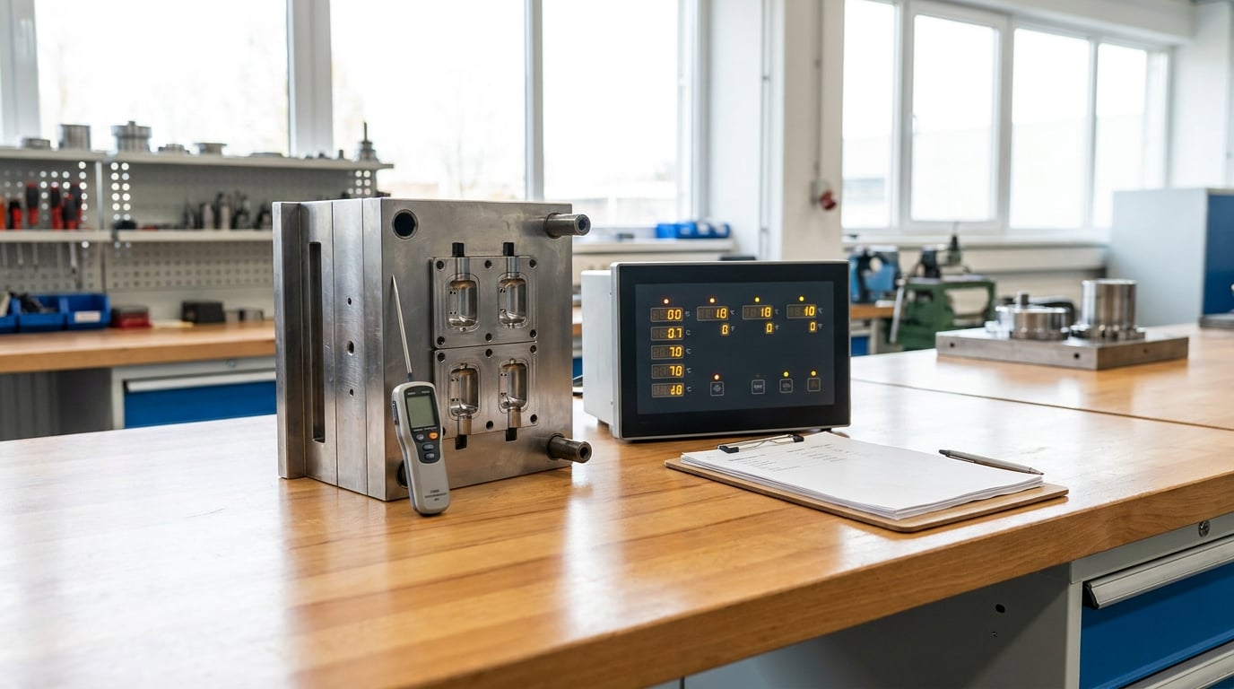
Mold temperature control best practices come down to three things: set a documented target for every zone, prove the tool is actually holding it, and trend the readings instead of trusting a single number. Get those right and warpage, sink marks, dimensional drift and long cycles all get easier to fix. Get them wrong and you will chase defects for months.
This guide walks through the whole job, from choosing targets to validating the finished process. Budget about a shift per tool for the first setup, and steady once you have a validated recipe. Last reviewed for 2026.
Table of Contents
- What You Need
- Step-by-Step: Apply Mold Temperature Control Best Practices
- 1. Set Mold Temperature Control Targets
- 2. Condition the Mold Before Production
- 3. Verify Temperature at Multiple Points
- 4. Balance Cooling and Heating Across the Mold
- 5. Control the Process Within a Stable Window
- 6. Monitor Trends Instead of Single Readings
- 7. Respond to Defects with a Root-Cause Process
- 8. Validate and Document the Final Process
- Common Mistakes
- Frequently Asked Questions
- What is the best way to control mold temperature in injection molding?
- How much temperature variation between mold zones is acceptable?
- Should I adjust mold temperature to fix sink marks?
- Why does my mold have hot spots even when the controller reads the correct temperature?
- How often should mold temperatures be checked during production?
- Do cooling-time changes solve temperature-related warpage?
- Conclusion
What You Need
You cannot apply mold temperature control best practices with a thermocouple and guesswork. Five things have to be on hand before anyone touches a setpoint.
- Machine and mold documentation. The machine’s water and oil circuit capacity, the mold’s cooling layout drawing, and the TCU manual for your model.
- Resin data. The supplier datasheet for the exact grade, including the recommended mold temperature range, drying conditions and shrinkage rate.
- Calibrated sensors. A surface or melt thermocouple probe for spot checks, plus in-mold thermocouples where uniformity really matters.
- Monitoring tools. Trend recording from the TCU or the machine’s data output, and a thermal imaging camera if you want to see hot spots before you cut steel.
- A defined acceptance range. A written tolerance for how far the mold may drift before the batch is suspect, agreed with quality before production starts.
One more piece of context worth having: what the part has to do. An optical lens, a snap-fit housing and a garden chair arm tolerate temperature error in completely different ways.
Step-by-Step: Apply Mold Temperature Control Best Practices
1. Set Mold Temperature Control Targets
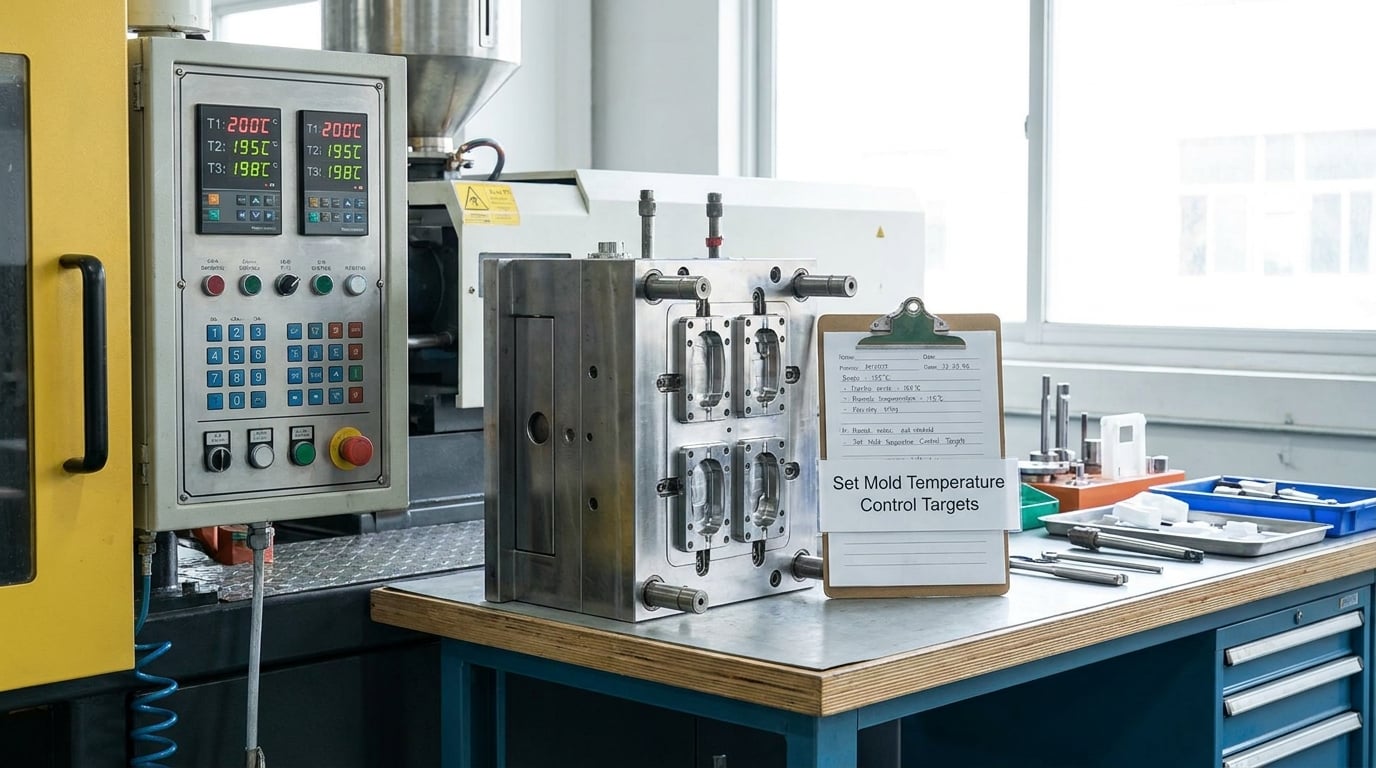
Set targets from the resin window, not from the last job that ran on that machine. Start at the low end of what the supplier recommends, raise only until the process stabilizes, and write down why each target is what it is.
Set core and cavity targets separately whenever the tool allows it. The core usually wants to run cooler for faster ejection; the cavity wants to run warmer for surface quality. A single setpoint for the whole tool is the most common compromise in the trade, and it costs you both properties.
Mark every value as either a starting point or a validated production setting. That distinction is what stops a trial number from quietly becoming the standard years later.
| Material | Typical mold temperature | Why it matters | Defect if set too low |
|---|---|---|---|
| ABS | 40-60°C / 105-140°F | Gloss and flow | Sink marks, poor gloss, jetting |
| PP | 30-60°C / 90-140°F | Shrink and stiffness | Warpage, long cycle |
| HDPE | 30-50°C / 90-120°F | Wide latitude; shrink is high | Weld lines, poor surface |
| PC | 80-120°C / 175-250°F | Stress relief, appearance | High internal stress |
| POM | 60-90°C / 140-195°F | Crystallinity, stability | Long cycle, warpage |
| Nylon 6/6 | 60-100°C / 140-210°F | Crystallinity, dry/as-moulded balance | Inconsistent shrinkage |
| Rigid PVC | 30-50°C / 90-120°F | Fusion, gloss | Poor fusion, stress whitening |
| PS | 20-50°C / 70-120°F | Appearance, dimensional stability | Sink marks, crazing |
| TPU | 40-70°C / 105-160°F | Surface, ejectability | Sticking, poor finish |
| PBT | 60-100°C / 140-210°F | Fill, crystallinity | Short shots, warpage |
These are starting ranges for trial work. Confirm every one against the datasheet for your grade and your wall thickness.
2. Condition the Mold Before Production
Bring the tool to temperature and hold it there before you judge anything. A tool that has just been connected reads setpoint on the controller while the cavity is still 40 degrees below it.
Once the target is reached, give the mold a settling period and confirm the readings at more than one point have stopped moving. Then cycle the mold open and closed a few times with no resin, so the parting faces and slides reach the same steady state they will see in production.
Cycle time measured before the tool is uniform is not a cycle time. Neither is a first-article dimension.
3. Verify Temperature at Multiple Points
The temperature your TCU displays is the temperature of the fluid returning from the mold. The steel near the gate sees something different, and so does the core pin on the far end of the tool.
Measure at the points that matter: the cavity surface near the gate, the far end of the cavity, the core, the sprue bushing, and each hot runner zone if the tool has one. In-mold thermocouples give you a continuous signal; a handheld probe gives you a spot check you can repeat during production.
Compare the readings against the fluid temperature. A gap of 5-10 degrees Celsius is normal between channel and cavity surface. A much larger gap points to scale, a fouled passage or a poorly seated thermocouple rather than a controller fault.
4. Balance Cooling and Heating Across the Mold
Uneven temperature shows up as uneven shrinkage, and uneven shrinkage shows up as warped parts. Look for hot spots around thick sections and away from cooling, and cold spots where flow is starved or a channel sits too far from the wall.
Fix them in this order: rebalance zone setpoints first because it costs nothing, then rebalance flow rates, then work on the mold. Compensating for a bad cooling layout with longer cooling time just converts a quality problem into a cost problem.
Your choice of heat transfer media limits what you can reach. Water is the best conductor of the three and the most trouble to live with; oil is the most forgiving and the worst conductor; glycol sits between them.
| Medium | Typical operating range | Main risk | Use it when |
|---|---|---|---|
| Water | Up to about 90°C / 195°F | Corrosion, contamination, scaling | Molds running below the cavitation limit with clean, treated circuits |
| Water-glycol | Up to about 120-140°C / 250-285°F | Oxidation, concentration drift, inhibitor depletion | Most general-purpose jobs needing both heating and cooling |
| Oil | Up to 200°C+ / 390°F+ | Lower heat transfer, oxidation, mess and fire handling | High-temperature engineering resins and tools above the water limit |
The practitioner rule on the switch from water to oil is simply cavitation. Above the temperature at which water boils at your pump’s suction pressure, water stops being an option, and oil becomes the correct answer rather than the fashionable one. Below that line, the move to oil trades a manageable corrosion problem for a less efficient and harder-to-handle system.
5. Control the Process Within a Stable Window
Mold temperature is one variable among several, and they pull on each other. Change fill speed or hold pressure and you have changed how the part cools even with the setpoint untouched. Change the resin grade and the whole window moves.
Keep resin drying on a schedule you can verify, with a moisture measurement rather than a timer. Make small setpoint changes and let the tool re-stabilize before drawing conclusions. Abrupt changes are the fastest route to dimensional variation between good parts.
Three temperatures get confused constantly. They are not interchangeable and only the first one is mold temperature.
| Temperature | What it controls | Who sets it |
|---|---|---|
| Mold temperature | Surface the part forms against, and cooling rate | TCU / mold temperature controller |
| Melt temperature | Viscosity of the melt entering the cavity | Barrel zones and screw |
| Barrel temperature | Plasticizing rate and melt homogeneity | Barrel heater zones |
On cooling time, a rule of thumb worth keeping: set cooling time roughly 1.5 to 2 seconds longer than screw recovery time. If cooling finishes well before the screw is ready, you are paying for idle time in every cycle.
6. Monitor Trends Instead of Single Readings
A single reading tells you almost nothing. A trend tells you everything.
Log zone and cavity temperatures, cycle time, part weight, key dimensions and defect counts together, and review them on the same shift schedule. Most temperature problems announce themselves as drift long before a part looks wrong: a slow 3-degree climb over a week is a fouled passage or a dying heater far more often than it is normal ambient change.
Set an alarm band around your acceptance range so the machine tells you rather than the customer.
7. Respond to Defects with a Root-Cause Process
Match the symptom to the temperature-related cause, test one change, and confirm the fix with measurements. Fixing defects by intuition produces settings nobody can explain two years later.
| Symptom | Likely temperature-related cause | Corrective action |
|---|---|---|
| Warpage | Uneven cooling across the part, or uneven wall shrinkage | Rebalance cooling near thick sections, confirm uniform cavity temperature, adjust flow rates |
| Sink marks | Surface held too long above the softening point | Raise mold temperature modestly, extend hold pressure to gate seal, add core support |
| Burn marks | Air trapped at the end of fill, or mold too hot locally | Improve venting, reduce the local temperature at the hot spot |
| Flash | Part and tool over-packed, mold too soft or too hot at the parting faces | Reduce hold pressure, increase clamp force, cool the parting faces |
| Short shots | Mold too cold, raising fill resistance and freezing the flow front | Raise mold temperature, increase fill speed or pressure |
| Weld lines | Cold mold slows the fronts meeting at the weld | Raise mold temperature, raise melt temperature within the resin window |
| Dimensional drift shot to shot | Zone setpoints moving, or a failing sensor or heater | Compare TCU trend against in-mold readings, verify sensors, restore the setpoint |
| Parts sticking | Core too hot, or mold surface too hot at release | Cool the core zone, add draft or polish the release surface |
8. Validate and Document the Final Process
Run enough shots at the final settings to see repeatability, then measure the dimensions and weights that matter against your drawing. Ten clean parts mean nothing if the hundredth differs.
Write down the final setpoints, the media used, the verification method and the acceptance band. When someone asks why the core runs 10 degrees below the cavity six months from now, the answer should be a document, not a memory.
Know where your authority ends. Changing a zone setpoint inside an approved range is a process adjustment. Changing the resin, the mold geometry, the cooling layout or the material of a cooling component is a change that needs engineering review and, in a regulated part, a formal validation update.
Common Mistakes
One setpoint for every zone. Core and cavity usually want different temperatures. Split them wherever the tool allows and adjust from there.
Trusting the controller readout. It measures the fluid, not the steel. Spot-check the cavity until you know your offset, then verify it periodically.
Changing settings during production without a record. Every adjustment, the time, who made it and what happened to the parts. No record, no learning.
Ignoring cooling uniformity in favor of setpoint accuracy. A mold dead on setpoint with a 15-degree spread cavity to cavity will still make warped parts.
Confusing air temperature with mold surface temperature. Room air is not the process variable and has no place in a mold temperature calculation.
Jumping to oil at the first sign of corrosion. Fix the circuit first. Inhibit it, check glycol concentration with a refractometer, flush it, and confirm the inhibitors are compatible with your seals. Oil solves a corrosion problem by removing the water, at the cost of heat transfer and handling.
Frequently Asked Questions
What is the best way to control mold temperature in injection molding?
A temperature control unit circulating water, water-glycol or oil through the mold’s cooling and heating channels, with in-mold thermocouples feeding a PID loop, gives the most repeatable result. Start at the low end of the resin supplier’s mold temperature window, condition the tool until it is thermally uniform, verify the cavity surface with a probe, and record every zone setpoint before production.
How much temperature variation between mold zones is acceptable?
For appearance-critical and dimensional parts, hold cavity-to-cavity variation within about 5°C / 9°F and keep the spread from widening during a run. For thick-walled structural parts you can work a little looser, around 10°C / 18°F. Anything beyond that tends to show up as differential shrinkage and warpage, so fix uniformity before you tighten anything else.
Should I adjust mold temperature to fix sink marks?
Yes, moderately raising mold temperature is one of the first levers to try, because a warmer surface delays the skin over the gate and lets more material pack underneath. But mold temperature alone rarely closes the problem. Check hold pressure and the time to gate seal next, and consider core support or a gate relocation if the marks sit on a thick boss.
Why does my mold have hot spots even when the controller reads the correct temperature?
The controller reports the fluid, and the fluid is only the transport. Hot spots usually come from thick sections with no nearby cooling channel, a blocked or scaled passage, unbalanced flow between circuits, or poor mold-to-tool thermal contact. Measure the surface with a probe or thermal camera to find the real pattern, then rebalance flow or add cooling rather than trusting the setpoint.
How often should mold temperatures be checked during production?
Once at start-up after conditioning, once at first-article approval, and at minimum at every changeover and material swap. During a run, trend the TCU and in-mold readings continuously and alarm on drift. A handheld surface probe check at the start of each shift catches sensor and heater failures that the setpoint will happily hide.
Do cooling-time changes solve temperature-related warpage?
No. Extra cooling time can freeze shrinkage in place, but it usually adds cycle cost without fixing the underlying imbalance. If warpage comes from uneven cooling, rebalance the circuits, correct the hot spot, or move the temperature setpoint. Use cooling time to protect ejection and gate seal, and to sit a set margin beyond screw recovery, not as a warpage fix.
Conclusion
If you do one thing this week, write down a documented target for each zone on the tool you are running most, then measure the actual cavity surface temperature rather than assuming it matches the controller. Confirm the mold is thermally uniform, put the zone and cavity trends on a screen somebody reviews every shift, and fix the first confirmed deviation before touching anything else. That sequence is the whole of mold temperature control best practices in practice, and it is what separates a process you can repeat from one you keep adjusting by feel.