
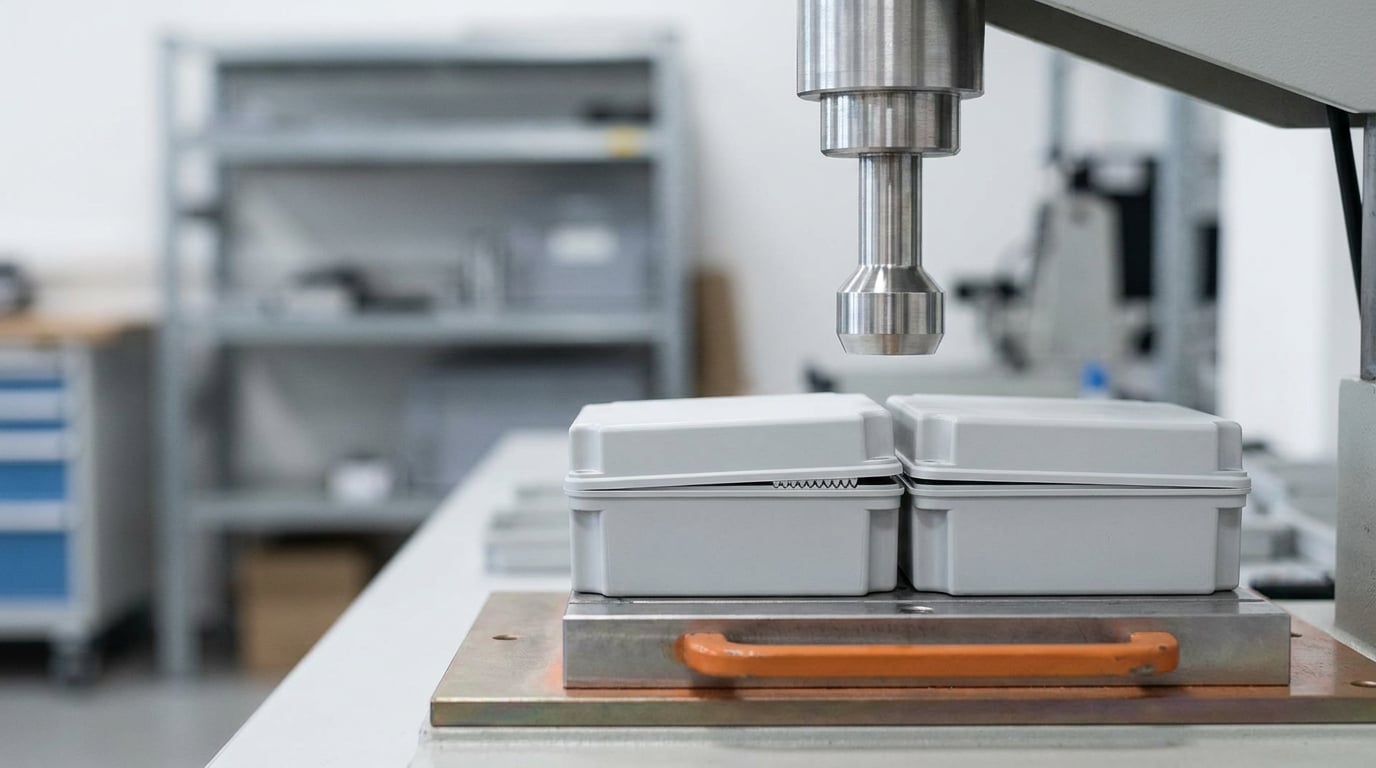
Ultrasonic welding of plastics is a solid-state joining process: high-frequency mechanical vibrations, typically 20 to 70 kHz, are applied through a metal horn to press two thermoplastic parts together under force. Friction at the interface melts the plastic locally, and the parts fuse into one joint as it cools under pressure.
That is the short version. The longer version is that a generator drives a piezoelectric transducer, a booster and a horn as a single tuned acoustic stack, the stack vibrates at its own resonant frequency with an amplitude of roughly 5 to 50 micrometers, and the joints cool in well under a second with no adhesive, no cure time and no fasteners. If you are specifying a joining method, understanding where that process breaks down matters as much as understanding where it works.
Table of Contents
- How Ultrasonic Welding of Plastics Works
- Which Plastic Materials Can Be Ultrasonically Welded
- Main Ultrasonic Welding Process Methods
- The Ultrasonic Welding Process Step by Step
- How Joint Design Affects Weld Strength
- Key Parameters That Control Weld Quality
- Common Ultrasonic Welding Defects and Their Causes
- How to Test and Validate an Ultrasonic Weld
- Advantages and Limitations for Plastic Manufacturers
- Safety, Noise and Guarding
- Frequently Asked Questions
- Conclusion
How Ultrasonic Welding of Plastics Works
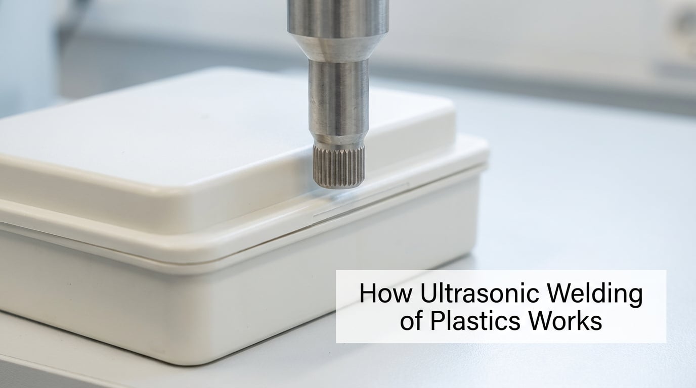
The process relies on friction heat, not on an external heater. A metal horn, sometimes called a sonotrode, presses against the part while vibrating. That vibration travels into the plastic and concentrates at the joint, where small molded features called energy directors collapse and generate heat. The surrounding plastic softens, the melt spreads under pressure, and the two parts become one piece.
The equipment stack has six parts worth knowing by name:
- Generator — the power supply. It converts mains electricity into high-frequency electrical energy at 20, 30, 35, 40, 50 or 70 kHz.
- Transducer — usually piezoelectric ceramic. It converts the electrical signal into mechanical vibration.
- Booster — increases or decreases the vibration amplitude to suit the part and tooling mass.
- Horn — the shaped tool that touches the part. Horn design matters more than most people expect.
- Nest or anvil — the fixture that supports and locates the parts.
- Press — applies and controls the clamping force.
Every element in that stack has to resonate at the same frequency. If the horn is machined badly or the part is clamped off its intended axis, the stack loses resonance and the weld suffers even though nothing visibly broke.
Two broad approaches fall out of this. In near-field welding, the horn touches the joint directly, which suits rigid, compact parts. In far-field welding, the horn drives a larger, more flexible component such as a film or a nonwoven, and the vibration travels to the joint through it. Continuous seam welding of textile and filter media is the classic far-field case.
Which Plastic Materials Can Be Ultrasonically Welded
Only thermoplastics can be ultrasonically welded. Thermosets, elastomers and thermoset composites cannot be remelted, so no amount of energy will fuse them. Among thermoplastics, the amorphous grades weld readily while semi-crystalline grades fight the process.
| Material | Structure | Weldability | Notes |
|---|---|---|---|
| ABS | Amorphous | Excellent | Wide process window, forgiving of minor surface variation |
| Polycarbonate (PC) | Amorphous | Very good | Must be dry; moisture causes sizzling and porosity |
| ABS/PC alloy | Amorphous | Excellent | Common in medical and electrical housings |
| PPO / polyphenylene oxide | Amorphous | Excellent | Often cited as one of the easiest to weld |
| Polysulfone, PEI | Amorphous | Very good | High-temperature medical and sterile applications |
| Nylon (PA 6, PA 66) | Semi-crystalline | Workable | Hygroscopic, so drying before welding is essential |
| Acetal (POM) | Semi-crystalline | Difficult | Narrow process window, prone to flash |
| Polypropylene (PP) | Semi-crystalline | Difficult | Usually needs a shear joint; prone to flash |
| Polyethylene (PE) | Semi-crystalline | Difficult | Very narrow melt range; specialist techniques only |
| PVC | Semi-crystalline | Difficult | Soft PVC welds under restricted conditions; rigid PVC is poor |
Semi-crystalline plastics have a sharp melting point rather than the broad softening window amorphous grades offer. There is no gummy stage, so the melt either sits in the gap or flows out as flash. This is why PP and PE parts normally use shear joints, which generate heat by friction over an area instead of relying on an energy director to focus it.
When welding two different plastics, three rules decide whether it works. Their glass transition temperatures should be within about 40 F of each other. Their melt flow indices should be similar, otherwise one side flows away before the other softens. And they must be chemically compatible enough that a stressed weld will not crack later.
Two more variables catch people out. Glass-fibre-filled grades shrink differently from unfilled ones and can warp, so keep fill level consistent across both parts. And moisture, especially in nylon and polycarbonate, boils at the joint and produces a weak, bubbly weld. Drying is not optional.
Main Ultrasonic Welding Process Methods
The method you pick depends mostly on the shape of the joint and how much of it needs to be sealed.
Spot welding
One or a few discrete points are welded through a sonotrode with an anvil beneath. It is fast and cheap, and it suits staking posts into a housing or attaching a cosmetic cover in a single spot. It is not a seal.
Seam welding
A rotating or linear horn sweeps along the joint to produce a continuous weld line. This is the method behind sealed drink pouches, medical tubing and filter membranes, where the whole seam has to be leak-tight.
Slash welding
A circular horn welds a continuous ring at one time, typically around a cap or a container neck. Cycle times are very short because an entire seal happens in a single stroke.
Ring welding
Similar to slash welding but driven by rotating anvil tooling rather than a single horn face, often with multiple rings welded simultaneously. It suits high-volume closures.
Horn-based welding
The general case: a shaped horn presses a flanged part onto a matching flange. Butt joints with energy directors, step joints, tongue-and-groove and shear joints all fall into this family, and most molded enclosures use it.
The Ultrasonic Welding Process Step by Step
A production cell runs the same sequence on every shot:
- Part preparation — parts are clean, dry and at a consistent temperature. Release residue or fingerprints at the joint are a leading cause of weak welds.
- Loading — one part nests in the anvil, the mating part is placed or the operator loads both by hand. Fixtures locate parts to within a few tenths of a millimeter.
- Clamping — the press brings the horn down and applies weld force. Force is a process parameter, not just a clamp; too little and the joint does not collapse properly.
- Weld trigger — energy is applied for a set weld time, a set energy, a set collapse distance or a set peak power. Time mode is the default on most machines.
- Energy delivery — amplitude at the horn face and clamping force determine how fast the energy directors melt. The plastic reaches a molten state only at the joint.
- Collapse and hold — pressure continues as the melt spreads. The hold period, typically a few hundred milliseconds, lets the joint solidify undisturbed.
- Cooling and release — the horn retracts and the part ejects. Total cycles are commonly under a second, which is why the method scales to high-volume production.
- Inspection — visual, leak or destructive testing depending on what the joint has to guarantee.
Cycle time is dominated by the weld and hold times, so tuning those two parameters is usually where throughput gains come from.
How Joint Design Affects Weld Strength
Ultrasonic welding is a design-dependent process. A joint that cannot concentrate energy at a small area will not weld well no matter how good the machine is.
The main split is by wall thickness. Below roughly 1.5 mm (0.060 in), energy directors work best because a small feature can melt the full section. Above roughly 3 mm (0.120 in), use a shear joint, where a tapered or stepped interface creates friction across a large area and the thick section acts as a heat sink.
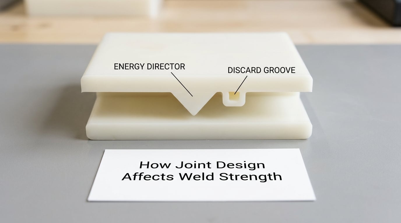
Energy directors are small triangular, semicircular or ridge features molded around the joint perimeter. Typical sizes run from about 0.5 mm to 1 mm tall and 0.8 mm to 1.5 mm at the base. Designers usually add a discard groove at the root of the director so flash has somewhere to go instead of creeping onto the visible face. A criss-cross pattern works better than a simple sawtooth because it melts from several directions at once.
Other design rules worth internalizing:
- Ribs and corners should transition smoothly; sharp internal corners concentrate stress and crack.
- Draft on a vertical wall should be light, so the wall is not scraped as the part collapses.
- Keep the collapse distance in mind. The joint must be allowed to close without the top part bottoming out on a feature.
- Keep the joint clean and free of release agent. Discussions about plastic joining keep circling back to contact surface condition, and they are right.
- Do not design cosmetic texture onto the sealing land. It becomes a leak path or flash trap.
Key Parameters That Control Weld Quality
| Parameter | Typical range | What it controls |
|---|---|---|
| Frequency | 20, 30, 35, 40, 50 or 70 kHz | Stack size, part size and material; 35 and 40 kHz are common general-purpose choices |
| Amplitude | 5 to 50 micrometers at the horn face | Rate of energy input and melt rate at the joint |
| Weld force | Set per part and material | Clamping, collapse and flash |
| Weld time | Typically 0.1 to 0.5 seconds | Total cycle when controlled by time mode |
| Hold / cool time | 0.1 to 0.5 seconds | Joint strength before ejection |
| Energy | Measured per weld | Consistency across tool wear and material variation |
| Collapse distance | Design-dependent, often 0.5 to 1.5 mm | Consistent joint thickness; the most repeatable mode for many parts |
The four control modes differ in what they hold constant. Time mode holds duration constant, which is simple but drifts with part temperature and material batch. Energy mode holds delivered energy constant and tolerates fouling better. Distance mode stops on collapse, so every joint ends at the same thickness. Power or weld-velocity mode is used for continuous seam and slash welding where throughput matters most.
Horn geometry deserves attention too. A horn face that is too large dumps energy across the whole part instead of the joint. Aluminium horns are standard; hardened steel or tungsten carbide extends life on abrasive or filled plastics at higher cost.
Common Ultrasonic Welding Defects and Their Causes
| Defect | Likely cause | What to change |
|---|---|---|
| Incomplete weld | Not enough energy, energy directors too small or missing, part misaligned | Increase amplitude or weld time; review director geometry; check fixture location |
| Flash | Too much energy, joint over-designed, mismatched melt flow between materials | Reduce energy; shrink the director; improve the discard groove |
| Burn marks or scorched surface | Excessive amplitude on thin walls, horn rubbing, dirty horn face | Lower amplitude; shorten weld time; clean and re-check horn face |
| Cracking on the weld line | Dissimilar materials, over-constrained joint, residual stress | Match materials better; add relief; reduce cooling stress |
| Warpage | Uneven wall thickness, unfilled or over-filled glass fibre, uneven cooling | Balance the weld perimeter; match fill levels; adjust hold time |
| Misalignment | Poor part geometry, worn fixture, excessive collapse distance | Fix tooling; reduce collapse distance; tighten part tolerances |
| Weak or porous weld | Moisture in the plastic, contamination at the joint, hold time too short | Dry the resin properly; clean contact surfaces; extend hold time |
Worth noting that the same symptom can come from opposite directions. Flash means too much energy, but an unfinished weld looks similar from the outside and means too little. Peel a failed sample open rather than guessing.
How to Test and Validate an Ultrasonic Weld
Validation starts before production with a design-of-experiments run on a few dozen parts, adjusting amplitude, force, weld time and hold time. From there:
- Visual inspection — look for a uniform witness ring, no flash on the cosmetic face, no burn marks and no visible gap.
- Leak testing — pressure decay or dye penetration for hermetic applications such as medical fluid paths, drinkware and battery housings.
- Pull or tensile testing — the standard quantitative check. Weld strength is usually expressed as a percentage of the base material strength.
- Peel testing — used for seam and pouch welds where strength per unit width matters.
- Destructive sectioning — cut samples open to check for voids, cold joints and uneven melt fronts.
- Process capability — run a capability study on the chosen control mode so drift is caught before it reaches a customer.
Set acceptance criteria before you start. A common one is a minimum weld strength as a percentage of base material, a zero-leak requirement on a defined sample size, and a visual standard with photographed examples of acceptable and rejected parts.
Advantages and Limitations for Plastic Manufacturers
The case for it is strong where parts are small, molded and high in volume.
- Cycle times under a second, with no cure, drying or solvent flash time
- No adhesives, no fasteners, so part count, weight and inventory drop
- Hermetic, airtight seals in a single process step
- No surface marks on cosmetic areas and no touch-up
- Highly repeatable and easy to automate with robotic cells
- Low energy use and no fumes or ventilation requirement
The limitations are equally real:
- It works only on compatible thermoplastics, and semi-crystalline grades are difficult
- It is limited by wall thickness, so thick sections need special joint designs or a different process
- It requires purpose-designed geometry; a joint that was not designed for welding will not perform
- Appearance suffers if flash is not designed for
- The machine, horn and fixture are a capital investment, and tooling is part-specific
- Contamination sensitivity is high, and a wet resin will produce a weak weld every time
When those limits start to bite, the honest move is to look at the alternatives side by side rather than argue yourself into the welding process.
| Method | Typical joint | Cycle time | Strengths | Limitations |
|---|---|---|---|---|
| Ultrasonic welding | Thin molded walls, energy director or shear joint | Under 1 second | Fastest, hermetic, no consumables, automatable | Thin sections only, sensitive to contamination |
| Spin welding | Round parts, circular seam | 1 to 5 seconds | Handles semi-crystalline plastics and thicker walls | Round parts only, slower, rotation inertia |
| Vibration welding | Large flat seams, automotive panels | 2 to 15 seconds | Big parts, strong hermetic seams, good on PP and PE | High capital cost, mechanical wear on linear vibrators |
| Hot plate welding | Large flat panels and containers | Seconds to minutes | Simple, forgiving, handles thick walls | Visible flash line, slow, heat exposure to the whole part |
| Hot air welding | Tubes and ducting | Continuous | Simple, handles large sections | Cooling time, process control is largely manual |
| Laser welding | Seams needing a clean cosmetic line | Under 1 second | Very precise, no mechanical contact, low thermal load | Expensive, limited to transmissive or absorbing grades |
| Adhesive bonding | Any geometry, dissimilar materials | Seconds plus cure | Joins anything, no tooling for part shape | Cure time, mess, volatile compounds, weaker joints |
| Mechanical fasteners | Any load case | Slowest | Repairable, no process knowledge needed | Added parts and weight, visible fasteners, holes weaken the part |
On strength, the honest answer is that a properly designed ultrasonic weld approaches the base material strength in the joint area, and it beats a typical two-part epoxy on creep and temperature resistance. What it does not beat is a screw in peel and shock loading, and it never matches a screw for serviceability. On cost, the machine and the part-specific horn and fixture are real capital, and they only pay back on volume. A shop running a handful of assemblies a week will usually be better served by a smaller machine, or by accepting a slower process.
Safety, Noise and Guarding
Ultrasonic welding is not hazardous in the way a press brake is, but the noise is real. Sub-harmonic components of the high-frequency vibration are audible to people, and running machines side by side without enclosures produces a persistent, tiring noise floor. Hearing protection is standard practice on production cells, and a sound enclosure around the stack usually pays for itself in operator comfort and in keeping the area usable for anything else.
Guarding matters because the horn moves fast under force. An interlocked guard over the press area prevents hands near the tool, and parts should be ejected or placed so they cannot reach a pinch point. Horns wear and can crack, so tooling inspection belongs on the same schedule as any other press maintenance. There are no fumes to extract, which is one of the process’s quieter advantages.
Frequently Asked Questions
What is ultrasonic welding and how does it work?
Ultrasonic welding joins thermoplastics by applying high-frequency mechanical vibrations, usually 20 to 70 kHz, through a metal horn while the parts are held together under force. Friction at the joint generates heat, small molded energy directors melt, and the parts fuse as the joint cools under pressure. There is no adhesive, no cure time and no fastener.
What plastics can be ultrasonically welded?
Amorphous thermoplastics weld well, including ABS, polycarbonate, ABS/PC alloy, PPO, polysulfone and PEI. Semi-crystalline grades such as nylon, acetal, polypropylene, polyethylene and PVC are difficult because they melt sharply rather than softening gradually, and they usually need a shear joint instead of an energy director. Thermosets cannot be welded at all.
What are the disadvantages of ultrasonic welding?
The main limitations are material compatibility, wall thickness limits and the need for purpose-designed joint geometry. Parts with flash-prone designs look poor, contamination at the contact surface causes weak welds, and the machine plus part-specific tooling represent a real capital investment. Thick sections and dissimilar semi-crystalline materials may be impossible to weld well at any parameter setting.
Can you ultrasonic weld metal to plastic?
Not directly. Metals cannot be melted by ultrasonic friction at plastic-process energy levels, so the metal is not the weld partner. Instead, the plastic part is welded onto the metal insert using staking or swaging, where a post is melted and formed over a knurled or dimpled metal feature. The result locks the two together and resists twisting and pull-out.
How do you design an energy director for ultrasonic welding?
Put a small raised feature around the entire joint perimeter, typically 0.5 to 1 mm tall and 0.8 to 1.5 mm at the base, pointing toward the mating part. Use a triangular, semicircular or criss-cross profile so heat starts at several points at once. Add a discard groove at the root so flash has somewhere to go, and keep the joint on thin sections below roughly 1.5 mm wall thickness.
What are the most common ultrasonic welding problems?
The most frequent issues are incomplete welds caused by low energy or missing energy directors, flash caused by excess energy, burn marks on thin walls, cracking along the weld line, warpage from uneven cooling, and weak welds caused by moisture or contamination at the contact surface. Peel failed samples open to tell an under-weld apart from an over-weld instead of guessing.
Conclusion
Ultrasonic welding of plastics is a fast, clean, hermetic joining method, but it earns its place only when the material, the joint and the parameters line up. Start by confirming the resin grade will weld at all, especially if polyolefins or PVC are involved.
Then design the joint deliberately: an energy director on thin walls, a shear joint on thick ones, and a discard groove for flash. Tune the process on representative parts rather than production parts, and confirm the result with pull testing and leak testing before you commit to a run.
Get those four steps right and the rest is cycle time. Get them wrong and no machine setting will rescue the joint.