
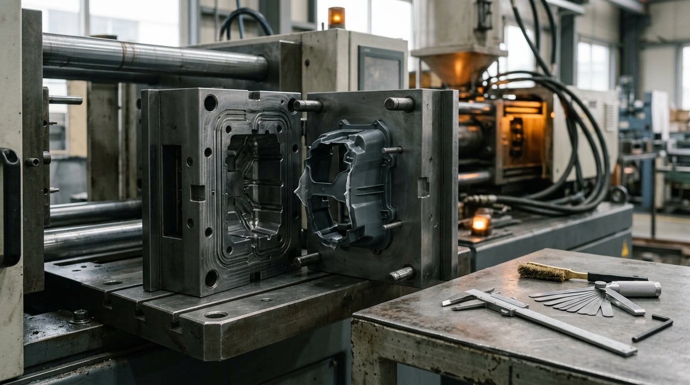
Mold flash is the thin layer of plastic that squeezes out at the parting line, around ejector pins or along a worn shutoff when the pressure inside the cavity beats the closing force of the mold. To answer what causes mold flash and how to prevent it in one line: cavity pressure exceeds what the tooling can resist, and you fix it by finding which part of the mold or the process is giving way. Usually it is one of five things — not enough clamp force, pressure spikes at transfer, poor venting, a worn or misaligned parting line, or a material running hotter and thinner than the window allows.
The tricky part is that all five look identical on the table. A 0.3 mm fin along the parting line reads the same whether it came from a cavitating vent or a guide pin that is no longer guiding. That is why most guides that treat flash as a settings problem end up chasing their tails for weeks.
This guide is written for molding engineers, quality teams and production staff. It covers what flash is, where it shows up, the real mechanisms behind it, and the order to check things in so you fix the cause rather than the symptom.
Table of Contents
- What Is Mold Flash and Why Does It Matter?
- Where Does Mold Flash Usually Appear?
- What Causes Mold Flash?
- Tooling, Material, and Machine Problems That Lead to Flash
- How Injection Molding Flash Is Diagnosed
- How Compression and Transfer Molding Produce Flash
- Process-Specific Prevention Checklist
- How to Stop Flash Without Creating Other Defects
- Prevention in Different Plastic Resin Families
- When Mold Flash Cannot Be Prevented
- Frequently Asked Questions
- Is mold flash always caused by excessive injection pressure?
- What is the difference between mold flash and a mold burr?
- Can mold flash be repaired without replacing the entire mold?
- Does lowering clamping pressure always prevent flash?
- Why does flash appear only in one cavity of a multi-cavity mold?
- When should a flash-related part be scrapped instead of reworked?
- Conclusion: Start at the Parting Line
What Is Mold Flash and Why Does It Matter?
Flash is extra material that was not part of the intended geometry but solidified attached to the part, usually as a thin web or fin. It forms wherever the mold halves, inserts or pins do not meet perfectly, or wherever the melt is pushed into a clearance that should be sealed.
It is worth separating flash from the defects it gets confused with, because each one points to a different cause:
- Flash is a thin extra layer on the surface, often continuous along the parting line or around one feature.
- Short shot is missing material — the fill did not complete. Flash and short shots usually appear together only when the process window has genuinely collapsed.
- Sink marks are depressions on the surface caused by thick sections cooling and shrinking from the inside. They sit in the wall, not at the split line.
- Warpage is a dimensional change across the whole part caused by uneven shrinkage and fiber orientation. It distorts the part rather than adding material to it.
- Knit or weld lines are weak seams where two flow fronts met. They can look like a faint ridge and are often mistaken for a small fin when the gate is close to the feature.
Why it matters runs well past cosmetics. Flash on a sealing surface blocks an O-ring or a gasket, and a seal that does not seal fails in the field. Flash on a cosmetic surface is a visible reject that a customer will photograph. Flash around an ejector pin often means there is a bigger problem underneath: a bent pin, a missing bushing, or a slide that is not fully locked before the cavity fills.
There is also a compounding effect. Once a fin exists, the pressure it creates pushes the mold halves slightly further apart, which pushes out more material. The defect feeds itself, and the flash you see on the first part of a run is smaller than the flash on the last part. That is why a flash problem that was tolerable three years ago quietly becomes scrap three years later.
Finally, flash is hard evidence of a tooling problem. Every shot that flashes is a shot where the mold opened or the shutoff leaked under load. If you see it consistently, something in the mold has moved past its wear limit.
Where Does Mold Flash Usually Appear?
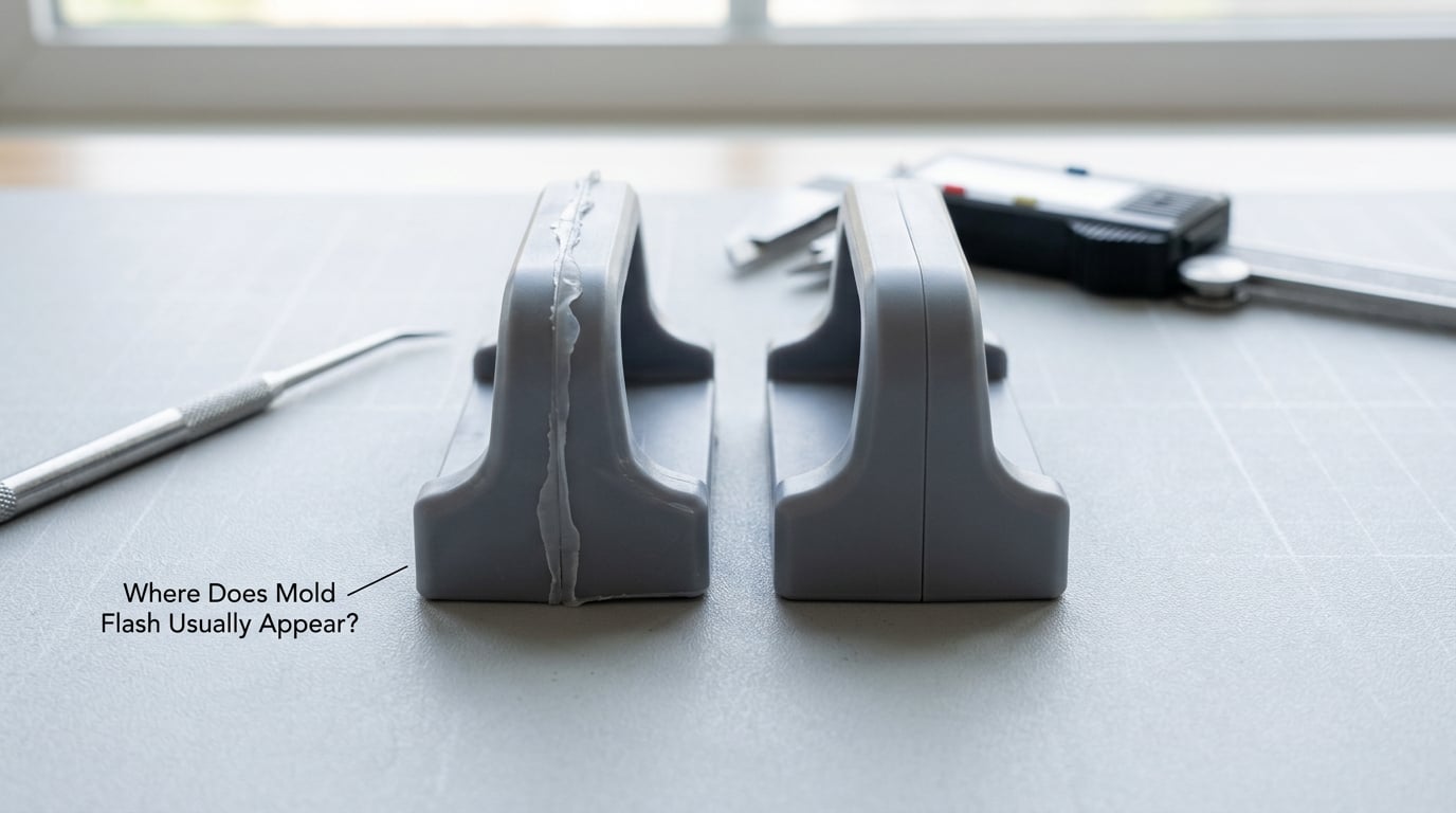
Location is the most useful diagnostic signal you have, because it narrows the search before you touch a single parameter. Flash along the full perimeter points to cavity pressure or clamp force. Flash at one spot points to tooling. Flash in one cavity of a family tool points to flow imbalance rather than a mold-wide problem.
Here is the mapping most shops use:
| Where the flash appears | What usually causes it | First thing to check |
|---|---|---|
| Even, continuous hairline along the whole parting line | Cavity pressure above available clamp force, or a mold that deflects open under load | Projected area and cavity pressure versus machine tonnage; check the parting line is parallel across the whole face |
| Flash concentrated near the gate or end of fill | High melt temperature, low viscosity, overpacking, or a transfer point set too late | Transfer position, melt temperature actual reading, and hold pressure and time |
| Flash around ejector pins, guide pins or core pins | Pin-to-bushing clearance beyond the mold’s wear limit, or a pin bent during ejection | Pin diameter and bushing ID; look for scoring on the pin |
| Flash at one shutoff or one insert edge | Differential thermal growth, local wear, a cracked or mis-seated insert, or debris in the shutoff | Spotting compound contact pattern; inspect the insert for chips |
| Flash on a slide, lifter or moving core | Slide not fully locked, a locking shoe worn past limit, or sequence timing out of position | Locking condition at the moment of injection; shoe contact faces |
| Flash in a single cavity of a multi-cavity mold | Unbalanced runner flow, a cold slug blocking that feed, or a nozzle/hot-runner difference | Compare part weight per cavity; check nozzle condition and hot-runner balance |
| Flash that appears only at the end of a long run | Mold heating up, part weight creeping, or flash land wear exposing fresh clearance | Part weight trend; mold surface temperature at steady state |
Two details narrow it further. Width tells you about energy — a wide fin means high pressure over a long fill, while a narrow intermittent sliver points to a mechanical gap that the melt only reaches at the end of fill. Continuity tells you about the mechanism: continuous flash along a whole line is a pressure problem, patchy flash at intervals is a geometry problem.
Measure it before you argue about it. A dial indicator or a feeler gauge against the shutoff, and a vernier on the fin height, gives you a number you can track across changes. Estimating from memory is how a slow wear problem turns into a sudden crisis.
What Causes Mold Flash?
The mechanism is simple. The cavity is not a sealed box — it is two steel halves held together by force, with a parting line between them that is not perfectly flat and a set of vents that are deliberately open. If the pressure generated inside the cavity is greater than the force holding the halves closed, the mold opens a few hundredths of a millimeter and pressurized melt escapes into that gap. It freezes almost instantly, and you get flash.
So there are always two questions: how much pressure, and how much resistance?
Clamp force is the resistance. The usual sizing rule of thumb is 3 to 5 tons of clamp force per square inch of projected part area, or roughly 41 to 69 MPa of pressure against the projected area. A 100 square inch part therefore wants somewhere between 300 and 500 tons. If the machine cannot deliver that, or if the setting is well below it, the mold has nothing holding it but its own weight and the friction of the tie bars.
Getting the number right matters in both directions. Under-clamping gives you flash and then part weight variation, because an open mold changes the effective cavity volume. Over-clamping deforms the platens and tie bars, which bows the mold faces and produces its own parting-line mismatch that no process setting can fix. A dial indicator check of platen parallelism and tie-bar strain balance, with the two sides within a few percent, tells you quickly whether your clamp is even.
Cavity pressure is the load. It builds during fill and peaks at transfer. A useful way to reduce the peak is to transfer earlier — at 95 to 98 percent fill rather than 99 percent — because the last one or two percent of fill is where cavity pressure spikes hardest. Trimming peak pressure usually removes flash without touching part weight, since gate freeze decides part weight long before the screw stops.
Temperature and viscosity work together on that pressure. A hotter melt flows more easily, so the same fill takes less pressure and pushes harder into every clearance it meets. Lowering melt temperature in small steps inside the resin supplier’s allowed range — five to ten degrees at a time — is often enough to bring flash under control. Verify with a needle pyrometer, because barrel setpoints on an aging machine routinely read well below the actual melt temperature.
Trapped gas is the under-discussed one. Vents exist so air ahead of the melt front can leave the cavity. When a vent is too shallow, too long, or clogged, that air compresses, the local cavity pressure spikes, and flash appears at the vent land. Glass-filled compounds are the usual suspects, and vent cleaning on a schedule rather than when burn marks show up is the fix. In the field, shops that clean vents every 8 to 12 hours running filled nylons report both fewer burn marks and noticeably less flash.
Packing and hold are the usual surprise. Hold pressure and hold time govern part weight, and gate freeze ends the hold. If hold is running long after the gate has sealed, you are adding pressure to a closed system — which does not help the part and does add stress. The clean way to set hold time is a gate-seal study: increase hold time in increments until part weight stops rising. That is your gate freeze point, and everything past it is wasted cycle time.
And flash can be self-reinforcing. A fin left on a part that goes back through a drill or a fixture is a stress riser. More practically, a mold that has been flashing for a long time wears its flash land and shutoffs faster, which widens the gap, which raises the pressure, which flashes more. Breaking that loop early is much cheaper than living with it.
Tooling, Material, and Machine Problems That Lead to Flash
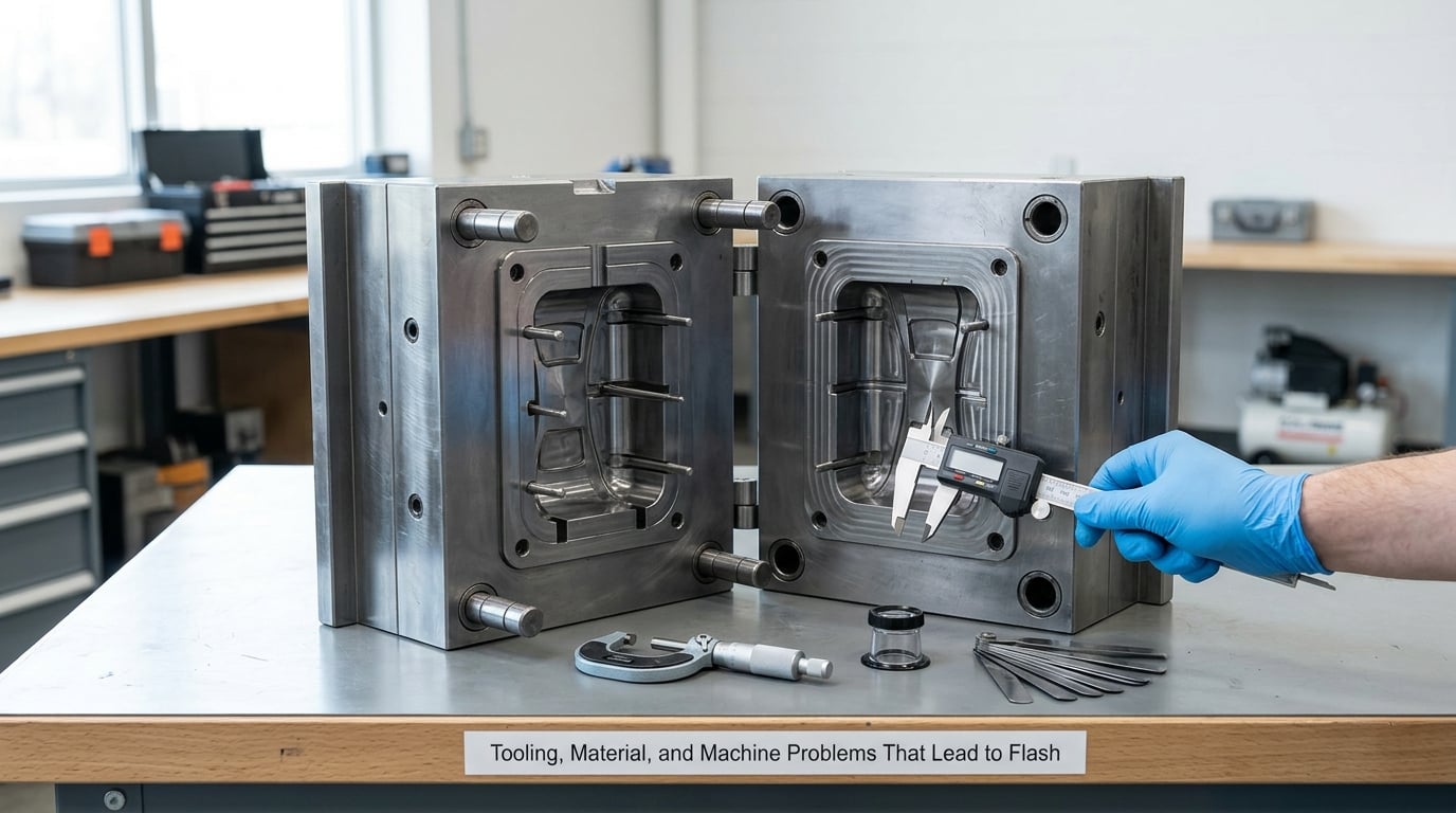
Not every flash is a process problem. This section is the one to read first when the flash appeared on a mold that ran clean for years.
Mold construction. The flash land is the raised area along the parting line that concentrates the closing force onto a small width. When it is too narrow, or the land is not supported by a backing rib, the mold deflects under load and the effective gap opens during injection. Parting line design also matters at shutoffs, where a vertical parting on a tall wall gives the melt an easy escape path. Mold design that puts a shutoff where the part is thickest is designing a flash problem into day one.
Mold condition. Guide pins and bushings wear, lose clearance and let the mold shift under injection load. That shift is what turns a small, uniform gap into a large local one. Inserts crack, lift or get chipped; foreign material — a fragment of steel, a piece of old flash, a screw — sits in the shutoff and holds it open. Ejector pins bend during a hard ejection and the part rubs past them. None of this announces itself; the flash just quietly gets worse.
The spotting check is the most useful tool here. Apply blue check compound to the shutoff faces, close the mold, open it, and read the contact pattern. A healthy pattern is even across the land. Patchy or edge-only contact means alignment or wear, and it shows up before any visible flash does.
Thermal growth deserves its own mention, because it is invisible in a cold mold. As the mold reaches operating temperature, core and cavity expand at different rates and by different amounts. A mold that closes perfectly on the bench can be mismatched at 60 degrees Celsius, and the flash lands are exactly where that mismatch shows. Measuring mold surface temperature rather than coolant setpoint is the only way to see it, and it is the usual explanation for flash that appears after a few thousand shots and then stays.
Material. Contamination and regrind raise the effective viscosity unpredictably, foreign matter in a filled compound clogs a vent and spikes local pressure, and moisture in hygroscopic resins such as PA, PET and PBT produces splay and can carry volatiles to the parting line. Degraded regrind also has a lower melt strength, so the same pressure produces more flow. Change the lot and flash changes with it — that is a material problem, and it will look random until you start tracking lot numbers against defect rates.
Machine. A barrel and screw that have gone a decade without service hold a charge longer, shear it more and change the melt delivered to the tool. An oversized machine running a small part has the same issue in reverse: a very short stroke means the screw barely retracts, cushion becomes inconsistent and the machine cannot control the transfer point repeatably. Injection and hold pressure calibration drifts, and a proportional valve that is not holding setpoint produces pressure spikes no cavity can survive. Verify the machine before you blame the mold — it is the cheaper check and the more embarrassing one to skip.
How Injection Molding Flash Is Diagnosed
Diagnosing flash works as a sequence, not a brainstorm. Each step narrows the field, and the point of the sequence is to avoid changing a setting that will disguise a tooling defect for a month.
- Confirm it is flash. Look at the location and whether material is added to the part or missing from it. If it is missing, you have a short shot and a different problem.
- Measure it. Fin height and width, location, and whether it is continuous or intermittent. Write the number down and date it. Flash that grows across a run is a wear or thermal problem, not a static setup error.
- Establish the pattern. All cavities or one? All shots or only after a material change, a tool change or a temperature change? Random flash usually points at the mold; consistent flash usually points at the process.
- Review the process as run. Compare setpoints against what the machine is actually delivering: verify melt temperature with a pyrometer, check transfer position, and review hold pressure and time against the last gate-seal study.
- Check the tooling before adjusting anything. Spotting compound on the parting line, a parting line thickness check with feeler gauges, guide pin and bushing inspection, and a visual check of ejector pins, slides and shutoffs.
- Check venting. Vent depth in the finished mold, vent condition under magnification, and how long the tool has been running filled material since the last clean.
- Change one variable. One setting, one increment, a defined number of shots, and a re-measurement. Two changes at once produce data you cannot read.
Some results mean stop and escalate rather than adjust. Flash on a shutoff that moves when the mold is spotted, a mold that will not close by hand, a parting line gap that is visibly open with the mold cold, or flash that reappears within a few hundred shots of a correct setting all say the tooling is outside its working condition. A parting line that cannot be brought within tolerance is a mold repair or a moldflow question, not a process one.
The pattern most shops settle on is unglamorous: tooling first, settings second. A chronic flash case that ends after a guide pin and bushing replacement, before anyone touches the clamp setting, is not a rare story. So is a flash problem that disappears once transfer is pulled back a few percent of fill. Either way, the mold had to be right before the process settings could hold anything.
How Compression and Transfer Molding Produce Flash
The defect is identical, but the pressure source changes, and so does the order of the checks.
In compression molding, a measured charge is placed in an open cavity and pressure is applied vertically. If the charge weight is too high for the cavity volume at molding temperature, there is nowhere for the excess to go but out. The same thing happens if the mold closes too fast and traps air, or if the charge is not level, or if the mold is too hot and the resin is more fluid than the process assumed. Charge weight is the single most common cause here, and it is the first thing to verify by weighing a sample of production charges.
In transfer molding, resin is transferred from a heated pot into a closed cavity at pressure. Here flash is usually the pot pressure being higher than the clamp on the mold, or a charge that is simply too large for the cavity. Mold temperature and resin flow at the transfer moment decide whether that pressure finds a parting line to escape through.
Across all three processes the same two levers exist: reduce the pressure reaching the parting line, or increase the resistance there. What differs is which control you have. Compression gives you charge weight and closure speed. Transfer gives you pot temperature and transfer rate. Injection gives you transfer position and pressure limits. Venting, shutoff condition and mold alignment still matter in every case.
What Causes Mold Flash and How to Prevent It in Practice
Put the two levers together and the working sequence is short enough to remember on a shop floor.
- Correct the tooling first: alignment, guide pins and bushings, ejector pin clearance, slide locking, and any insert that has moved.
- Establish and verify a parting line. Spot the shutoff, measure with feeler gauges, and record the value so wear becomes visible before flash does.
- Maintain the flash land. Support it properly, keep it clean, and re-machine or replace a worn land rather than adjusting the process around it.
- Clean the vents and confirm vent depth is appropriate to the material. Deeper vents suit lower-viscosity melts, shallower vents suit filled materials that would otherwise burn.
- Control fill and pack: transfer at 95 to 98 percent fill, set hold from a gate-seal study, and stop hold at gate freeze.
- Manage temperature and material condition. Keep melt temperature inside the supplier’s range, verify it with a pyrometer, and control moisture and regrind rate.
- Validate through a controlled trial — one variable, a defined sample, measured results — before releasing the process to production.
Process-Specific Prevention Checklist
Injection molding
- Inspect the parting line with spotting compound; record gap measurements at fixed points.
- Confirm clamp tonnage against projected area and cavity pressure, and check platen parallelism and tie-bar balance.
- Verify actual melt temperature with a pyrometer, not the barrel setpoint.
- Check transfer position and review the gate-seal study for hold pressure and hold time.
- Inspect vents under magnification; clean on a schedule based on material and hours run.
- Check guide pins, bushings, ejector pins and Slide locking faces.
- Track part weight by cavity and by lot; a drift is an early warning.
Compression molding
- Weigh production charges against the qualified charge weight for that cavity and material.
- Confirm charge placement is level and consistent, including on preforms and blanks.
- Review mold closure speed and the prepress step to make sure air can escape.
- Verify mold temperature at the surface, not just the controller reading.
- Inspect the parting line and any pressure pad or flash land for wear.
- Confirm the cavity is vented or that the charge is positioned to let displaced air leave.
Transfer molding
- Check pot temperature and the dwell time before transfer.
- Confirm transfer pressure at the mold is within the tool’s capability and that the mold is fully closed and locked before transfer.
- Re-verify charge or pot feed weight consistency batch to batch.
- Inspect shutoffs and vents, which take the same abuse as injection tooling but get less attention.
- Check ejector and core pin clearances on heated rubber and resin molds, where wear is fast.
How to Stop Flash Without Creating Other Defects
The most common mistake is reaching for clamp force. Adding tonnage to a mold that will not close properly hides the symptom, distorts the platens, and leaves the actual wear untouched. The part may look better for a while and then flash worse than before.
The second mistake is cutting hold pressure or hold time to reduce pressure at the parting line. That is a direct trade: part weight drops, sink marks and voids get worse, and dimensional stability falls, because the pack stage is what controls shrinkage in the thick sections.
Shortening cooling time to buy cycle time has the same signature problem. The part leaves the mold before it has shrunk enough, so it comes out slightly larger and the flash is still there — you have simply made the flash harder to trim because the part is warmer and softer when deflashed.
A safer order of attack: verify the parting line and alignment, then venting, then transfer position and peak pressure, then temperature, then material condition. Change one thing at a time and give each change a defined number of shots plus a measurement. If a correct set of parameters still flashes, stop adjusting and put the mold on the bench.
It is also worth checking whether the flash is actually acceptable to the part’s function. A 0.1 mm fin on a non-critical cosmetic rib may pass, and trimming is a legitimate part of the process for some families. What is never acceptable is flash on a sealing surface, a bearing fit, a snap-fit, or anything with a documented dimensional limit. Deburring and vibratory finishing can handle general flash; knife trimming on a sealing face introduces the risk of a secondary defect that is harder to detect than the original problem.
Prevention in Different Plastic Resin Families
The mechanism never changes, but the sensitivity does, and the same settings that suit one family will flash on another.
- Thermosets and compression-molded compounds flow under pressure rather than shear viscosity alone, so charge weight and mold temperature dominate. A small excess charge flashes; a small charge under a pressure-sensitive resin gives short shots. Charge weight is the control, not the setpoints.
- Commodity thermoplastics such as PP and ABS have a wide processing window and low viscosity when hot. They flash mainly from high melt temperature, late transfer or overpacking, and they respond quickly to those three adjustments.
- Engineering resins such as PA66, PBT and PET are moisture-sensitive. Wet resin produces splay and can carry volatiles to the parting line, and drying specification becomes part of flash control.
- High-shrinkage polymers amplify the underlying cause. A molded-in stress that would barely register in a low-shrinkage resin will distort enough to open a parting line in a high-shrinkage one. Flash on these grades is often a warpage problem presenting as a flash problem.
- Glass- and mineral-filled compounds are the hardest to run. Filler raises viscosity, sharpens wear on shutoffs, abrades vent lands and carries into the parting line. Higher viscosity means higher cavity pressure, so these grades need more clamp force, more careful vent design and a disciplined cleaning interval. Shops running GF nylon typically re-machine parting line inserts somewhere between 50,000 and 100,000 cycles.
- Long-fiber-reinforced materials carry fibers to the surface, where they resist the melt and raise local pressure. Fiber orientation also drives anisotropic shrinkage, which stresses a part unevenly and can open a parting line on its own.
None of this means one universal setting exists. It means the tolerance for sloppiness differs by family, and the record of a process sheet should say which family it was qualified on.
When Mold Flash Cannot Be Prevented
Some flash is a design conflict, not a process error. If the parting line is drawn on a draft-free vertical wall, if a shutoff sits where the melt is hottest and fastest, or if a slide has no positive lock, then the tool will flash at any sensible setpoint and the honest answer is a tool change.
Between a design conflict and a correctable upset sits a middle category that a lot of shops handle badly. A controlled repair is reasonable when the defect is localized, the rest of the tool is within wear limits and the repair restores the geometry the design intended: re-machining a flash land, replacing a worn guide pin and bushing, spotting and lapping a shutoff, replacing a cracked insert, or adding a small relief or seal detail. What is not reasonable is building up and hand-fitting a parting surface to make a worn mold pass, because the result will drift again and the next person will not know what was done to it.
Redesign becomes the answer when the flash land cannot be made wide enough, when the projected area exceeds what the machine can clamp, when the part geometry makes a leak path unavoidable, or when a wear rate calculation says the tool will not hold tolerance before its next rebuild.
Part-level decisions follow a written criterion rather than a mood. Accept by concession when flash is below the documented limit, is on a non-functional surface, and the part has been assessed against the drawing and the AQL in force for that part number. Rework when flash is within a set limit and the rework method is qualified for that material and geometry. Scrap when flash is on a sealing or bearing surface above tolerance, when it is intermittent in a way the customer cannot live with, or when trimming would take the part below a minimum wall thickness.
Writing that criterion before the problem appears is worth an hour. Deciding it at the inspection table at the end of a long run is how teams end up shipping parts they should have scrapped.
Frequently Asked Questions
Is mold flash always caused by excessive injection pressure?
No. Pressure is only one of several mechanisms. Flash also comes from insufficient clamp force for the projected area, a worn or misaligned parting line, oversized guide pin and bushing clearance, a clogged vent, a material running hotter and thinner than qualified, or trapped air compressing ahead of the melt front. Cutting injection pressure can hide the symptom while leaving a vented cavity or a worn flash land still in the mold, and the flash returns as soon as the tool is warm.
What is the difference between mold flash and a mold burr?
They are the same defect described with different words in different shops. Flash is the industry term for the thin extra layer of solidified polymer along the parting line, around pins or at a shutoff. Burr is the more general machining term and is often used for the same flash after trimming, or for any small ragged edge. In practice a burr reported on a molded part is flash that was trimmed imperfectly or a flash defect described by a finishing operator.
Can mold flash be repaired without replacing the entire mold?
Usually yes, when the problem is wear rather than design. Re-machining the flash land, replacing worn guide pins and bushings, lapping shutoff faces, and replacing a cracked or lifted insert are all normal shop repairs. A full mold replacement is only justified when the parting line cannot be restored, the flash land is too narrow to machine, or the projected area exceeds what the machine can clamp. Any repair should be recorded so the next wear check knows what was changed.
Does lowering clamping pressure always prevent flash?
It is backwards. Clamping pressure is what holds the mold shut against cavity pressure, so lowering it reduces the resistance to flash. What people usually mean is that they should check the clamp setting is actually sufficient for the projected area and cavity pressure. A mold that is already over-clamped can be deflecting, which opens the parting line mechanically. If a correct clamp setting still flashes, the cause is elsewhere, most often alignment or wear.
Why does flash appear only in one cavity of a multi-cavity mold?
A single-cavity pattern points to flow imbalance rather than a mold-wide pressure problem. Common causes are an unbalanced runner, a cold slug blocking that cavity’s feed, a nozzle or hot-runner difference between stations, or that cavity sitting a different distance from the gate. Compare part weight by cavity first, because a cavity running light is often the same cavity that flashes. If part weights match and one cavity still flashes, look at venting and shutoff condition in that cavity.
When should a flash-related part be scrapped instead of reworked?
Scrap the part when flash sits on a functional surface, such as a sealing face, bearing fit or snap-fit, and exceeds the documented limit. Also scrap when trimming would take the wall below minimum thickness, when the flash is intermittent in a way that suggests an unstable process, or when the part has already been through a rework step and cannot be verified against the drawing. Rework is reasonable for light flash on non-functional surfaces where the deburring method is qualified for that material and geometry.
Conclusion: Start at the Parting Line
When flash shows up, work the problem in a fixed order. Confirm the defect and its exact location, then measure it so you have a number to move. Inspect mold closure, flash lands and alignment with spotting compound before changing anything. Review venting and the actual cavity pressure in the process record, and make one controlled change at a time.
Most flash is not a mysterious process problem. It is a mold that has moved, a vent that is clogged, or a pressure spike that no shutoff should ever have to withstand. Knowing what causes mold flash and how to prevent it comes down to catching that at the parting line while the fix is still a cleaning or a half-point of transfer time, rather than a mold rebuild.