
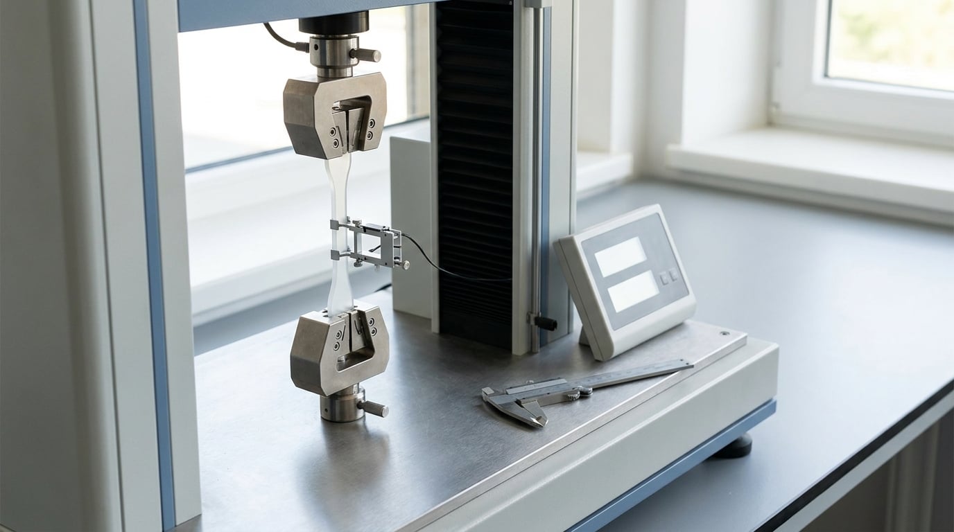
ASTM D638 is the standard test method for determining the tensile properties of plastics. It covers unreinforced and reinforced plastics tested as dog-bone specimens, and it produces tensile strength at yield, tensile strength at break, modulus of elasticity, and elongation at break from a single stress-strain curve.
The tricky part isn’t the standard, it’s the variables behind it. Speeds, thickness, conditioning, grip type, and machining quality can each shift the reported number more than a few percent, so a D638 number without its test conditions isn’t worth much.
This guide walks through what the method measures, which specimen to pick, how to condition and run the test, how to read the curve, and what makes a result invalid. It reflects the D638-22 revision; always work from the official ASTM document for the clause text and your contract’s specified revision.
Table of Contents
- What Is the ASTM D638 Tensile Test?
- What Does ASTM D638 Measure?
- ASTM D638 Test Specimens and Material Types
- How to Prepare and Condition a Test Specimen
- How to Run an ASTM D638 Tensile Test
- How to Read the Stress-Strain Curve
- How to Calculate ASTM D638 Results
- How to Control Crosshead Speed and Test Variables
- How to Report ASTM D638 Results
- Common ASTM D638 Testing Mistakes
- Frequently Asked Questions
- What is the ASTM D638 test method?
- What are the sample dimensions for the ASTM D638 tensile test method?
- How do you interpret tensile strength data?
- Which ASTM standard is used for tensile testing, and when is D638 the wrong choice?
- What is ASTM D695, and how is it different from D638?
- How many specimens does an ASTM D638 run need, and how long does it take?
- Conclusion: Start With the Right Specimen and Test Conditions
What Is the ASTM D638 Tensile Test?
ASTM D638 is the ASTM standard test method for determining the tensile properties of plastics. It covers unreinforced and reinforced plastics in five defined specimen shapes, tested in tension at a controlled rate until fracture, and yields an engineering stress-strain curve from which the reported properties are calculated.
The method is written for rigid and semi-rigid plastics, roughly anything that holds a shape in a dog-bone coupon. Specimen thickness has to stay between 1.0 mm and 14 mm for the standard geometry. Foil, thin film, and very flexible elastomers fall outside the scope and need a different method.
Two things D638 does not do. It doesn’t give you a true stress-strain curve for a polymer that necks heavily, because the reported values are engineering values based on the original cross-section. And it doesn’t tell you how a part will behave in service; it tells you how a coupon of that material behaves at a known rate, temperature, and humidity.
What Does ASTM D638 Measure?
Every reported value comes from the same two data streams: force from the load cell and extension from the extensometer or crosshead displacement. What follows is what you can legitimately report from a D638 run.
| Property | What it is | Why it matters |
|---|---|---|
| Tensile strength at yield | Maximum engineering stress before the material yields, in MPa | Stress at which a part starts to deform permanently; the design limit for most structural parts |
| Tensile strength at break | Engineering stress at the moment of fracture, in MPa | Failure-load reference for brittle materials, especially reinforced grades |
| Ultimate tensile strength | Highest engineering stress reached anywhere on the curve, in MPa | Peak capability of the material, even if it fails before reaching it in a real part |
| Modulus of elasticity (tensile modulus) | Slope of the initial linear portion of the curve, in MPa | Stiffness; drives deflection, stress distribution, and shrinkage-compensation maths |
| Offset yield strength | Stress where the curve crosses a line offset from the elastic slope, commonly 0.2 percent | Works for materials that yield gradually with no clear break in slope |
| Elongation at yield | Percent strain at the yield point | Indicates how much slack a part has before permanent set |
| Elongation at break | Percent increase in gauge length at fracture | Ductility; the single most useful number for forming and for impact expectations |
| Secant modulus | Slope between the origin and a chosen stress or strain point | Useful at high stress for reinforced grades with a poor initial slope |
| Nominal strain at break | Strain at fracture expressed on the constant cross-section basis | Required reporting for some fibre-reinforced plastic grades |
| Poisson’s ratio | Lateral strain divided by axial strain | Derived from a separate transverse strain measurement; not always reported |
Which ASTM standard covers tensile testing of other materials?
D638 is the plastics method, and it is often the wrong one for a given job. ASTM groups tensile testing into separate documents by material class, and picking the neighbouring standard instead avoids a report that nobody will accept.
- ASTM D638 — tensile properties of rigid and semi-rigid plastics.
- ASTM D695 — compressive properties of rigid plastics. D695 is the compression counterpart to D638; it reports compressive strength and compressive modulus, not tensile data.
- ASTM D790 — flexural properties of unreinforced and reinforced plastics, including fibre-reinforced plastic pultruded shapes.
- ASTM D412 — tensile properties of vulcanized rubber and thermoplastic elastomers.
- ASTM D828 — tensile properties of adhesives and adhesive bonds.
- ASTM D1876 — tensile properties of fibre-reinforced plastic pultruded bar.
- ASTM D3039 — tensile properties of fibre-reinforced plastic pultruded shapes and certain fibre-reinforced plastic plate.
- ASTM E8/E8M — tensile testing of metallic materials. Round or flat metal coupons, different specimen proportions entirely.
- ISO 527 — the international equivalent for plastics, split into five parts.
ASTM D638 Test Specimens and Material Types
The five specimen types exist because not every plastic can be moulded into the same shape. Type I is the default for rigid and semi-rigid moulded or machined plastics. Type IV handles thin, flat stock. Type V is a parallel-sided strip for very flexible material, where a tapered dog-bone would tear at the shoulders.
The table below gives the nominal geometry most labs work to. Treat the numbers as a working reference and confirm against the specimen table in the revision of D638 your specification calls out, because the standard is periodically reissued.
| Type | Overall length (mm) | Gauge length (mm) | Narrow section width (mm) | Width at ends (mm) | Thickness (mm) | Typical use |
|---|---|---|---|---|---|---|
| I | 165 | 50 ± 0.5 | 7 ± 0.5 | 19 ± 0.5 | 4 ± 0.2 | Rigid and semi-rigid plastics; the default coupon |
| II | 175 | 50 ± 0.5 | 7 ± 0.5 | 19 ± 0.5 | 4 ± 0.2 | Materials hard to mould into a Type I shape |
| III | 115 | 25 ± 0.5 | 6 ± 0.5 | 13 ± 0.5 | 1.0 – 3.2 | Thin or small parts, and machined test blanks |
| IV | 115 | 25 ± 0.5 | 6 ± 0.5 | 13 ± 0.5 | 0.8 – 1.8 | Thin sheet, film, and sheeting stock |
| V | 150 | 50 ± 1.0 | 2.0 – 4.0 (parallel-sided gauge) | 6.5 – 9.0 | under 1.0 | Highly flexible plastics and elastomers that would tear at a shoulder radius |
All measurements inside the parentheses are tolerances, not alternatives. A coupon machined to the wrong width or with a shoulder radius that isn’t the specified 60 to 75 degrees can shift strength by several percent on its own, so a micrometer and a radius gauge belong in the same kit as the machine.
Label every coupon with a specimen number, material designation, moulding or machining direction, and the nominal thickness batch. Labs that test a mix of materials in one run usually scribe a mark or dot near the grip end, away from the gauge section, rather than write on the gauge length itself.
How to Prepare and Condition a Test Specimen
Preparation decides whether the test is worth running. A coupon cut on a CNC with a sharp tool and a machined radius will typically break in the gauge section; the same material cut with a worn cutter or a rough band saw will break at a stress concentration and read low. Machine every edge in one pass, keep the shoulder radius within spec, and deburr the gauge section lightly.
Moulded parts are preferable where the process allows, because a moulded coupon carries the real process history. If you must machine, cut in the fill direction a part would actually see, and never compare a machined coupon against a moulded allowable without saying so in the report.
Measure the width and thickness of the narrow section at three positions and use the mean. Record the gauge length between the extensometer knife edges, not the machine’s crosshead distance. The area used in every stress calculation is the original cross-sectional area of the narrow section, and errors here propagate straight into the reported strength.
Conditioning and environment control
Condition specimens at a controlled temperature and relative humidity before testing, following the conditioning requirements the method calls for, and keep them in that environment through the test if the material is sensitive. Polyamides, polycarbonate, PET, PMMA, and other hygroscopic grades absorb moisture from the air and change measurably over a few days. A coupon conditioned for a week in a humid shop can read noticeably stiffer and stronger than the same resin tested dry.
Test at a stated temperature. Labs that test in a room without control should say so in the report, because a result is only comparable when the temperature is on paper.
3D-printed and composite specimen caveats
For FDM and other additively manufactured coupons, print orientation changes the answer. Layer adhesion usually governs the weak direction, so a coupon printed flat can show a very different strength and elongation from the same coupon printed upright. State the orientation, the infill, and the nozzle and layer height, or the numbers mean nothing outside your own build.
For fibre-reinforced coupons, gripping is the hard part. Practitioners add doubler plates at roughly 45 degrees to spread the clamp load and prevent a clamping break, and they track fibre breakage load separately from the ultimate value, including the intermediate fibre breakage events that appear partway through a run. A coupon that fails in the grip has measured your grips, not your material.
How to Run an ASTM D638 Tensile Test
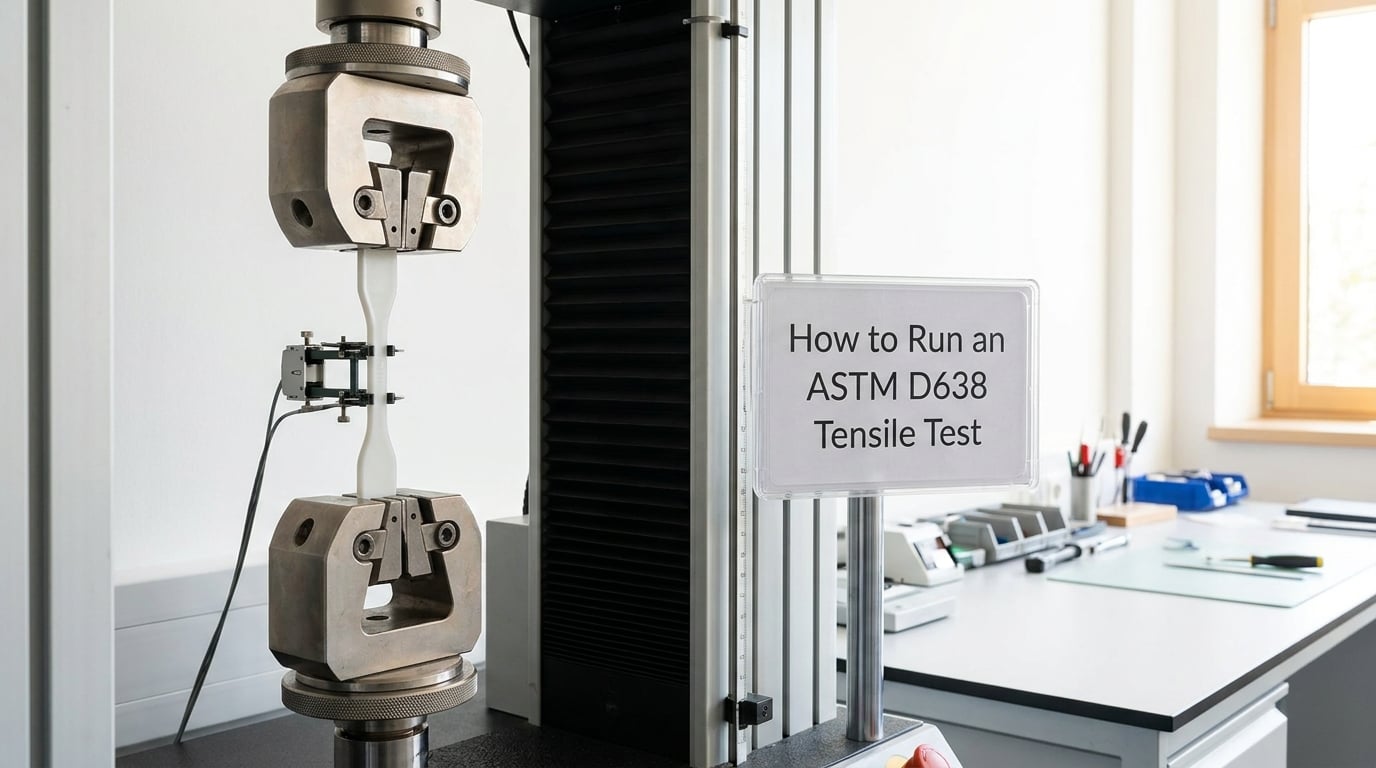
Eight steps, in order. Most invalid tests come from skipping the alignment or the conditioning, not from the machine.
- Condition the specimens. Hold them at the specified temperature and humidity for the required period, then test under the same conditions.
- Measure and record the geometry. Width and thickness of the narrow section at three points, gauge length, and the calculated cross-sectional area.
- Select the load cell and grips. Use a cell that keeps the working load inside roughly 10 percent to 100 percent of capacity, and wedge-action grips sized to the specimen’s grip section.
- Mount the specimen and align it. Clamp so the specimen axis is collinear with the load path. Use a light initial preload and check that the extensometer sits squarely on the gauge section.
- Attach the extensometer. A clip-on extensometer over the gauge length is what makes the modulus credible; crosshead travel alone carries grip and frame compliance into the slope.
- Set the crosshead speed. Use the standard rate for the specimen type unless the specification says otherwise, and don’t change it mid-run.
- Load to failure. Record the full force-extension trace, and note where the break happened, in the gauge section or at the grip.
- Check the run and calculate. Confirm the break was in the gauge section and away from the shoulders before reporting anything.
Stop the test if the specimen slips in the grips, if the extensometer is knocked off, or if the trace shows a sudden load drop without fracture. A run like that is void, and re-testing on a fresh coupon is the only fix.
How to Read the Stress-Strain Curve
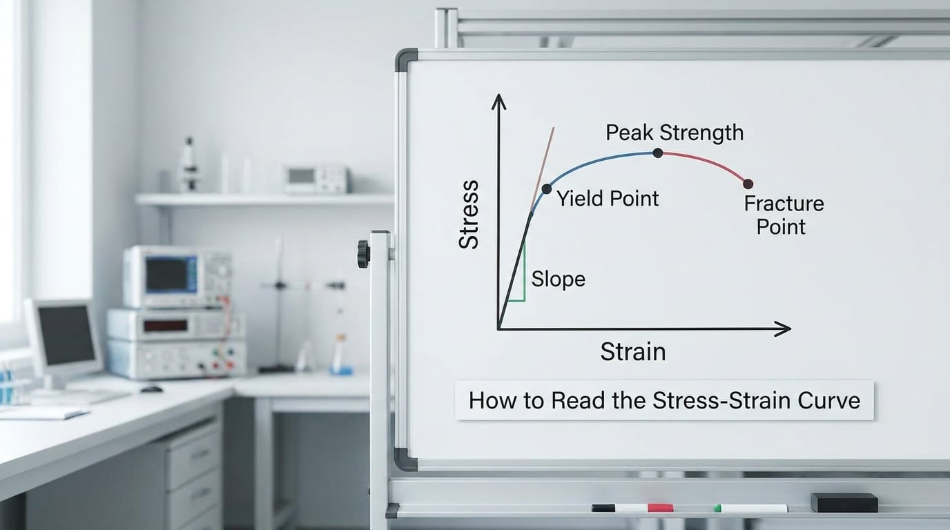
A plastics curve has five regions worth naming, and what you’re looking for changes completely between a brittle polymer and a ductile one.
The first region is the elastic region, a straight line where strain is recoverable. Its slope is the tensile modulus, and the steepness tells you how much the part will deflect under load. Anything you read from this section should come from the extensometer, not the crosshead.
Next is the yield. A sharp polymer yields with a clear knee. A ductile polymer rounds the knee over a range of strains, which is why the method allows an offset yield: draw a line parallel to the initial slope starting at 0.2 percent strain, and take the stress where the curve crosses it.
The third region is the plastic region, where strain accumulates permanently. In a ductile material the curve keeps climbing to the ultimate tensile strength and then necks, with the engineering stress falling as the cross-section shrinks. Engineering stress never accounts for that shrinking area, so a ductile material’s curve understates true stress after the peak.
The peak is the ultimate tensile strength. Depending on the material, the number reported in your test report may be the stress at yield or the stress at break, and the two can differ a lot. For a glass-filled nylon, yield and break are close. For a tough ABS, yield and break differ substantially.
The last region is fracture, read as elongation at break. A brittle specimen ends with a sudden drop and near-zero elongation; a ductile one has already extended several percent before the same drop. A high elongation value on a reinforced grade is usually a sign of a wet specimen, not a tough material.
How to Calculate ASTM D638 Results
Everything derives from force and extension, so the arithmetic is short. Work in consistent units: newtons, millimetres, megapascals, and percent.
Engineering stress: tensile stress equals the load divided by the original cross-sectional area. In practice, stress in MPa equals force in newtons divided by the narrow-section area in square millimetres.
Engineering strain: strain equals the change in gauge length divided by the original gauge length. Multiply by 100 to express it as percent.
Tensile strength: the maximum stress reached, taken at yield, at break, or wherever the curve peaks, depending on what the specification asks for.
Modulus of elasticity: the slope of the initial linear portion, equal to the change in stress divided by the change in strain over that region. Fit the steepest consistent segment early in the curve, not a best fit across the whole graph.
Offset yield strength: the stress at the intersection of the curve with a line drawn parallel to the elastic slope and offset by the specified strain, usually 0.2 percent or 0.5 percent.
Elongation at break: the change in gauge length at fracture divided by the original gauge length, times 100.
A worked example from raw data
Take a Type I coupon with a narrow section measuring 13.0 mm wide by 4.0 mm thick, giving a cross-sectional area of 52.0 square millimetres, and a gauge length of 50.0 mm. The load cell peaks at 2350 N, so the tensile strength works out to 2350 divided by 52.0, or about 45.2 MPa.
Now the modulus. At 500 N the stress is 500 divided by 52.0, which is 9.6 MPa. If the extensometer reads 1.25 mm of extension at that point, the strain is 1.25 divided by 50.0, or 0.025, which is 2.5 percent. Modulus is 9.6 divided by 0.025, giving roughly 385 MPa.
For elongation, the extensometer records 14.5 mm at fracture. That is 14.5 divided by 50.0, or 29 percent elongation at break. With five specimens you then report the mean of each value plus the standard deviation, and reject any run that broke in the grip rather than the gauge section.
How to Control Crosshead Speed and Test Variables
Plastics are rate-sensitive. A coupon pulled faster reads stronger and stiffer and usually elongates less, so two labs at different speeds can disagree on the same lot of resin. Speed is a controlled variable, not a convenience setting.
The method works with a constant rate of extension machine, commonly an electromechanical or hydraulic universal testing machine, at a crosshead speed in the range of about 5 to 50 mm per minute, with 5 mm per minute as the standard rate for rigid and semi-rigid coupons. The right choice follows the material: a brittle stiff polymer handles the standard rate, a very ductile material can neck unpredictably at a slow rate, and thin coupons need slower speeds to avoid a rate effect through thickness. Follow the specification when one exists.
Beyond speed, the variables that move your numbers are conditioning, test temperature, specimen thickness and geometry, grip type and alignment, extensometer versus crosshead strain measurement, machine compliance, and calibration. A frame that has not been checked in a year can shift the modulus even when the load cell is fine, because frame flex shows up in the crosshead channel and the modulus is the most compliance-sensitive value you report.
For reinforced coupons, the reported property can also be the fibre breakage load or the intermediate fibre breakage load rather than the ultimate value, and your spec should say which. If you are choosing between running the test in-house and sending it to a third-party lab, the practical comparison is sample throughput and whether someone in-house can machine good coupons; a lab with the right fixture and a bad coupon still gives you a wrong answer.
How to Report ASTM D638 Results
A test report is only useful if someone else could repeat it. The method specifies what has to be on the page, and a report missing any of the following will get challenged in a design review or an audit.
- Identification of the material, including grade, manufacturer, lot, and date of manufacture.
- Specimen type, dimensions of the narrow section, gauge length, and how the coupon was produced, including moulding or machining direction.
- Conditioning environment, conditioning duration, and test temperature and humidity.
- Crosshead speed, load cell capacity and calibration date, grip type, and the strain measurement method.
- Individual results for each specimen, then the mean and standard deviation for each reported property.
- The specific properties reported, meaning whether strength is at yield or at break, and the offset used for yield where one applies.
- Any deviation from the standard method, and how many specimens were discarded and why.
State the revision of the standard you tested to. Two reports both claiming ASTM D638 results mean very little if one followed D638-14 and the other D638-22.
Common ASTM D638 Testing Mistakes
Almost every voided D638 run falls into one of these patterns, and each has a fix that costs nothing.
| Symptom | Likely cause | Fix |
|---|---|---|
| Specimen breaks in or near the grips | Clamping break from sharp grip jaws, a bad shoulder radius, or misalignment | Use grip faces matched to the coupon, add 45 degree doubler plates on composites, and re-align on the load axis |
| Load drops without the specimen breaking | Slippage inside the grips | Add grip pressure, clean the faces, check the wedge engagement, and re-mark the coupon to check for movement |
| Strength far below the expected value | Break in a transition radius rather than the parallel gauge section, from a sharp machining cut | Machine in one pass, hold the specified shoulder radius, deburr the gauge section lightly |
| Modulus far lower than the material datasheet | Strain taken from the crosshead instead of an extensometer, so frame compliance flattens the slope | Fit a clip-on extensometer over the gauge length and derive the slope from that data |
| Scatter greater than expected across five coupons | Conditioning drift, moisture in a hygroscopic resin, or thickness variation between coupons | Condition all coupons together, measure each one, and check the machining direction matches the datasheet |
| All results running high versus a reference lab | Crosshead speed too fast for the material | Re-run at the specified constant rate of extension and record the speed on the report |
| Elongation far higher than expected on a reinforced grade | Specimen tested wet, or fibre breakage rather than final rupture used as the endpoint | Control conditioning humidity and state which failure point the number refers to |
One last habit worth keeping: record where the break happened on every specimen, in the gauge section or in the grip. It takes a second and it tells you immediately whether the run is usable.
Frequently Asked Questions
What is the ASTM D638 test method?
ASTM D638 is the standard test method for determining the tensile properties of plastics. A conditioned dog-bone specimen is clamped in the grips of a constant-rate-of-extension universal testing machine and pulled lengthwise until it fractures, while a load cell measures force and an extensometer measures extension. From that data the method gives tensile strength, modulus of elasticity, and elongation.
What are the sample dimensions for the ASTM D638 tensile test method?
The five specimen types share a dog-bone shape with different proportions. Type I is 165 mm long with a 50 mm gauge length, a 10 mm gauge width, a 7 mm narrow section, a 19 mm end width, and roughly 4 mm thickness. Types III and IV are 115 mm long with a 25 mm gauge length for thin and thin-sheet stock, and Type V is a 150 mm parallel-sided strip for very flexible material.
How do you interpret tensile strength data?
Read the slope of the initial linear region as the tensile modulus, then find where the curve first stops being straight, either as a clear yield point or through a 0.2 percent offset line. The peak of the curve is the ultimate tensile strength, and the strain at fracture is the elongation at break. Whether you report strength at yield or at break depends on the material and your specification, and for ductile plastics the two differ considerably.
Which ASTM standard is used for tensile testing, and when is D638 the wrong choice?
ASTM D638 is the tensile method for rigid and semi-rigid plastics. Use ASTM D412 for rubber and thermoplastic elastomers, E8/E8M for metals, D828 for adhesives, D3039 for fibre-reinforced plate and pultruded shapes, and D790 for flexure rather than tension. D638 also sits outside its scope for foil and very thin film, and for heavily orthotropic laminates a method built around unidirectional composites is a better fit.
What is ASTM D695, and how is it different from D638?
ASTM D695 is the standard test method for compressive properties of rigid and semi-rigid plastics. Where D638 pulls a coupon in tension and reports tensile strength, tensile modulus, and elongation, D695 pushes a specimen, usually a short cylinder or a prism, between platens and reports compressive strength and compressive modulus. Materials can rank differently under the two tests, so design allowables should state which one they came from.
How many specimens does an ASTM D638 run need, and how long does it take?
Five specimens per material is the working norm for a reported result, reported as a mean with a standard deviation, and any specimen that fails in the grip or slips is discarded and replaced. Conditioning is the long pole and can take a full day or more, while the tensile run itself takes a few minutes per coupon. Budget most of a day for a batch once the coupons are machined and the machine is free.
Conclusion: Start With the Right Specimen and Test Conditions
A defensible result from the ASTM D638 tensile test explained here comes down to four things you can control before the machine ever starts moving.
First, identify the material and the right specimen type. Type I is the default for rigid and semi-rigid plastics; thinner stock and very flexible material need Types III, IV, or V. Cut the coupon to the specified dimensions and radius, because that alone can move strength by several percent.
Second, condition it properly. Hygroscopic grades like polyamide, polycarbonate, PET, and PMMA change measurably with humidity, and an uncontrolled conditioning history is a result you can’t defend later.
Third, verify the machine settings: load cell in range, grips matched and aligned, extensometer on the gauge section, and the standard constant rate of extension. Record the speed on the report.
Fourth, read the whole curve rather than one number. Tensile strength, modulus, and elongation at break describe different failure modes, and a design decision made on a single property is usually the wrong one. Then check where each specimen broke before anything goes in the report.