
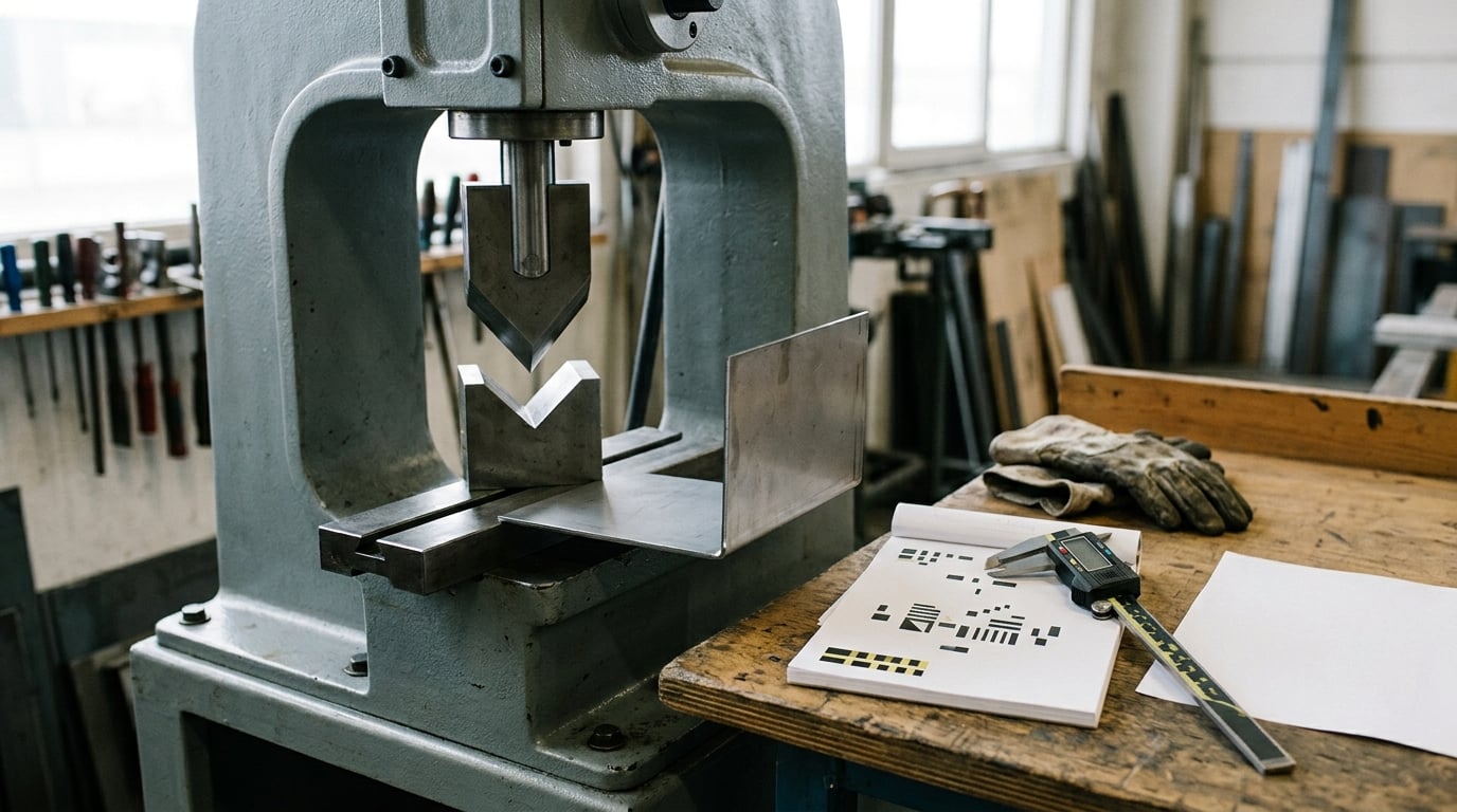
Clamping tonnage is the force a press holds across its tooling to resist the separating force created during a bend or a fill. You select it by working from projected part area and cavity pressure, or from bend geometry and material strength, adding a 20 to 30 percent margin, then confirming the machine also meets the shot size, mold size, tie bar and cycle requirements. The whole exercise takes about twenty minutes with the data listed below, and it is the difference between a machine that runs your part repeatably and one that flashes, sinks the tooling or sits idle half the day.
This guide covers both presses that share the phrase. A press brake holds tooling against a bending force. An injection molding machine holds a mold closed against cavity pressure while the resin cools. The math differs, the failure modes differ, and the numbers people quote for one do not transfer to the other.
One last framing point before we start. Most of the confusion I have seen in spec sheets comes from mixing tonnage units. A metric tonne is 9.807 kN, a US short ton is 8.897 kN, so a machine rated in one system is roughly 10 percent stronger than the same number in the other. Confirm the unit on the data plate before comparing any number to a calculation, especially on a machine bought second hand. The tables here were reviewed for 2026.
Table of Contents
- What You Need
- Step-by-Step: How to Select Clamping Tonnage for a Press
- Common Mistakes
- Frequently Asked Questions
- Is more clamping tonnage always better?
- What is the formula for clamping force in injection molding?
- Can I set press tonnage below the machine rating?
- How do I choose a safety factor for tonnage?
- What other machine specs must I check besides tonnage?
- What is the rule of 8 for V-die opening on a press brake?
- Conclusion
What You Need
Gather this before you calculate anything. A missing number at the start becomes a wrong press at the end.
- Projected part area for molding, in square centimeters, measured as the silhouette of the part in the parting plane, not its surface area.
- Estimated cavity pressure in MPa, usually taken from a resin data sheet or an existing validated process rather than guessed.
- Cavity count and shot weight in grams, so the machine shot capacity can be checked as well as the force.
- Resin density in g/cm3, used to convert fill volume to shot weight.
- Mold weight, platen size and tie bar spacing from the machine data sheet, plus the number of tie bars you can fit your mold between.
- Material thickness, yield and tensile strength for bending, in the same units you will use in the formula.
- Bend length in millimeters and the longest bend in the part, not the average.
- V-die opening and bend method, because air bending, bottoming and coining do not use the same force.
- Press rated clamping force plus its own stated speed, daylight and shot capacity ratings.
Two items are worth extra attention. Get the projected area from the actual 3D model or a print, and include every cavity and any runner that sits in the parting plane, because runners add separating force too. And take bend length from the longest bend, since a 600 mm bend takes proportionally more force than a 300 mm one on the same part.
Step-by-Step: How to Select Clamping Tonnage for a Press
Confirm the Part and Tooling Requirements
Start with what the press must actually do. For molding, that means projected area, shot weight per cavity, cavity count, resin grade, cycle target, and whether the tool uses hot runner, sliders, lifters or inserts that add side load. For bending, it means thickness, grade, longest bend, flanges, bend count per part and the bend method your process uses.
Write all of it on one sheet. In a spec review I have run, the parts that fail at trial usually failed because the mold weight or the insert loading was never on the sheet, so nobody checked the machine against it. The mold must be weighed or estimated, not assumed.
Calculate the Theoretical Clamping Force
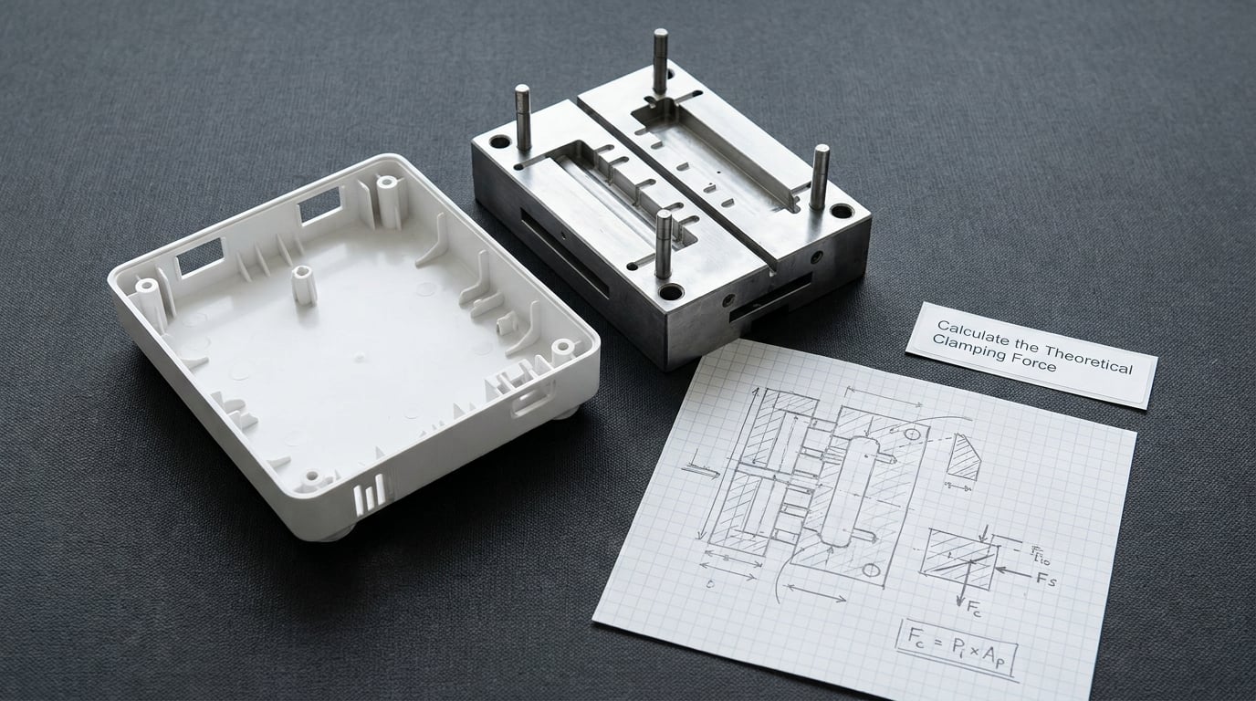
For injection molding, clamping force equals projected area multiplied by cavity pressure, then by a safety factor:
Clamping force (kN) = projected area (cm2) x cavity pressure (MPa) x safety factor
Worked example: a 400 cm2 projected area at 30 MPa with a 1.2 safety factor gives 1,440 kN, or about 147 tonnes of clamping force. The same figure in US tons is 161. If your part is 30 percent larger, the requirement scales by the same ratio, because both terms are linear.
The theoretical number is a floor, not a target. Cavity pressure varies across the fill, peak pressure sits at the gate, and a momentary spike can exceed the nominal value. Running the press at exactly the calculated force leaves nothing to absorb that peak.
For press brake air bending, the standard industry calculation is:
Bending force (N) = 650 x S2 x L x tensile factor / V
where S is material thickness in millimeters, L is bend length in millimeters, V is V-die opening in millimeters, and the tensile factor normalizes the material against mild steel at 1.0. Stainless at 1.5 means 50 percent more force than mild steel of the same thickness. This figure is the air bending force at the punch, before tooling load limits are applied.
Adjust for Material, Cavity Count, and Process Risk
These adjustments change the inputs, they are not arbitrary multipliers bolted on at the end. Cavity pressure belongs to the resin and the flow length, not to the machine. A long flow path in a thin wall drops peak pressure, while a short flow into a thick section or a packing step can push it well above the nominal figure. Pull the value from the resin data sheet or from a validated process on a similar part, then widen the margin if the part carries a tight tolerance, a cosmetic Class A surface, or tight wall thickness.
On the bending side, yield and tensile strength drive the tensile factor, and the V-die opening drives the force. Widening the V-die from 6 times thickness to 12 times thickness roughly halves the force, which is why tooling selection is a tonnage decision and not just a geometry decision. Bend angle, flange length, multiple bends on one part, and the metal form all shift the number too. A flange shorter than about twice the thickness cannot form cleanly and needs over-bending, which adds force.
Keep a written record of the factor you chose and the reason. Reviewers and auditors ask about that, and a quoted multiplier without a source turns into an argument.
Compare Calculated Force with Press Capacity
Now line the calculated operating requirement against what the machine is rated for. The press should have rated capacity above your calculated operating requirement, and rated capacity below the point where the ram, tie bars or bed begin to deflect badly. That band is where you want to operate.
| Check | Requirement |
|---|---|
| Rated clamping force | Above calculated operating force, typically with 20 to 30 percent headroom |
| Tie bar spacing and platen size | Mold footprint fits between tie bars with clearance for the nozzle and the mold |
| Daylight and open height | Tool opens far enough to clear the part and any core pull or insert action |
| Max mold weight, with and without rail | Mold weight is within limit on the side you intend to hang it |
| Shot capacity | Maximum shot is 1.1 to 2 times the part shot weight, never less |
| Nozzle and sprue geometry | Sphere diameter and tip length match your sprue bushing |
| Centerline load limit (brakes) | Bending at the center of a wide bend does not exceed the ram limit |
| Tooling load limit (brakes) | Shoulder loading per inch of die is within the tooling maker rating |
A press that clears force but fails the tie bar or shot capacity check is the wrong machine. There are plenty of them on the used market, which is exactly where a written checklist pays for itself.
Validate the Tonnage with Fill and Injection Checks
Plenty of parts get the force right and the process wrong. Check that the proposed machine can deliver the shot volume inside the cycle: barrel capacity, plasticizing rate and screw recovery all eat into the cycle, and a machine that can hold the force but cannot fill in time will still produce short shots. A useful rule is that the fill portion of the cycle should use no more than about half of the total cycle time, leaving room for cooling.
On a brake, the equivalent check is the V-die opening against the inside radius you need, and the tooling load limit against the shoulder width you have. An oversized press used to compensate for a badly chosen die produces flash on the shoulder, a cracked punch and inconsistent angles, and no amount of extra tonnage fixes it.
Watch for the telltale signs of a mismatch: flash that grows with tonnage, sinks around heavy inserts, warped panels, or a bend angle that drifts as the material heats up. Each points to a different cause, and only one of them is a tonnage problem.
Run a Controlled Trial and Finalize the Setup
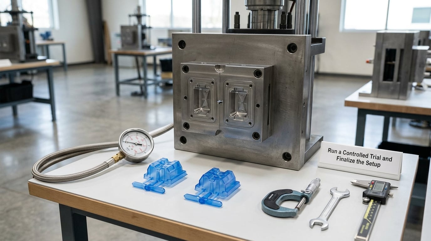
A calculation gets you to the trial. The trial closes the decision. Start conservative on force, verify cavity pressure with a sensor in the tool rather than from a press readout, and record the actual peak.
- Part weight checked against the calculated shot, at least ten pieces per cavity.
- Dimensions measured on a first article, especially the features that drove your tolerance concern.
- Flash and short-shot review at the lowest and highest force you intend to run.
- Cycle time timed with the tonnage you are holding, not at maximum speed.
- Final operating tonnage written into the process sheet, along with the reason for the margin you chose.
Then document the machine choice, the tooling set, the material factor, and the data you used. Six months later, when someone asks why the shop runs that press on that part, the answer takes thirty seconds instead of an afternoon.
Common Mistakes
These seven errors show up again and again, and every one has a straightforward correction.
Using part weight instead of projected area. Weight does not drive mold opening force. Only the area in the parting plane pressing against the resin does. Recalculate from projected area.
Applying the safety factor twice. Once in the cavity pressure and again as a machine multiplier, you end up 40 percent over. Apply it once, at the end, and note where it came from.
Picking the machine on tonnage alone. A press that meets force and fails on shot capacity, tie bars or mold weight is not a candidate. Run the full check table before you compare machines.
Ignoring the centerline load limit. A ram rated for a certain full-length force may deflect badly when the load is concentrated at the center of a long bend. Check the limit for the specific geometry you will use.
Overlooking mold weight and daylight. The tool has to hang, open and eject on the machine. Confirm both figures against the data sheet before anything else.
Using one factor for every material. A tensile factor that is right for mild steel understates stainless by half and high strength steel by far more. Look the factor up per grade and per thickness.
Setting tonnage without watching fill or flash. Force settings without a trial are guesses. Run the part, measure the peak cavity pressure, and adjust the number you wrote down.
One more habit worth keeping: record the assumption next to every number. Six months later, assumptions are the only part of a spec sheet that quietly goes out of date.
Frequently Asked Questions
Is more clamping tonnage always better?
No. Excess force does not improve a part, and it can push flash, distort thin walls and load the tie bars harder than they are rated for. You want the press rated capacity above your calculated operating force, not as high as possible. Keep the press in the band where the ram, tie bars and bed stay well within their deflection limits and the process still has enough force to control the peak pressure spike.
What is the formula for clamping force in injection molding?
Clamping force in kN equals projected area in cm2 multiplied by cavity pressure in MPa and by a safety factor. A 400 cm2 part at 30 MPa with a 1.2 safety factor gives 1,440 kN, about 147 tonnes. Convert to tonnes by dividing kN by 9.807, and to US tons by dividing by 8.897. Use peak cavity pressure, not the nominal value, when one is available.
Can I set press tonnage below the machine rating?
Yes, and you should. Operating force is normally set between 10 and 30 percent of rated capacity so the machine is not held at its limit, which causes heat, energy waste and accelerated wear on the hydraulics. Running near the rating also leaves nothing to absorb a pressure spike from a thick section, an insert or a packing step. The rating is a ceiling, not a target.
How do I choose a safety factor for tonnage?
Use 20 to 30 percent for stable, low risk work with a validated cavity pressure, and move toward 30 percent or above for tight tolerances, Class A cosmetic surfaces, insert molding, thin walls and long flow paths where pressure varies. The factor covers the difference between nominal and peak pressure, so pick it once and write down the reason next to it.
What other machine specs must I check besides tonnage?
Check shot capacity against the part weight with at least 10 percent headroom, mold weight on the side you will hang the tool, tie bar spacing against the mold footprint, platen size, daylight and open height, nozzle and sprue bushing geometry, plasticizing rate against your cycle target, and for brakes the centerline load limit and tooling shoulder load limit. Force is one of about eight numbers that decide whether a machine fits.
What is the rule of 8 for V-die opening on a press brake?
The rule of 8 says the V-die opening should be about eight times the material thickness. It is a starting point for material up to roughly 3 mm, and heavier material usually runs 6 to 10 times thickness. Die opening matters more to force than thickness does, so choosing a wide die can cut required air bending force dramatically. Always confirm the resulting inside radius fits your part drawing.
Conclusion
Start with projected area and process pressure, or with bend geometry and material strength, and calculate the force before you look at a single machine data sheet. Add a margin you can justify in writing, usually 20 to 30 percent. Then confirm the press also meets shot size, mold size, tie bar, daylight and cycle requirements, and finish with a controlled trial that measures the real cavity pressure and part weight.
That order matters because force is the number everyone quotes and the number least often decides the outcome on its own. Get it roughly right early so you are comparing the right machines, then let the trial have the final word.