
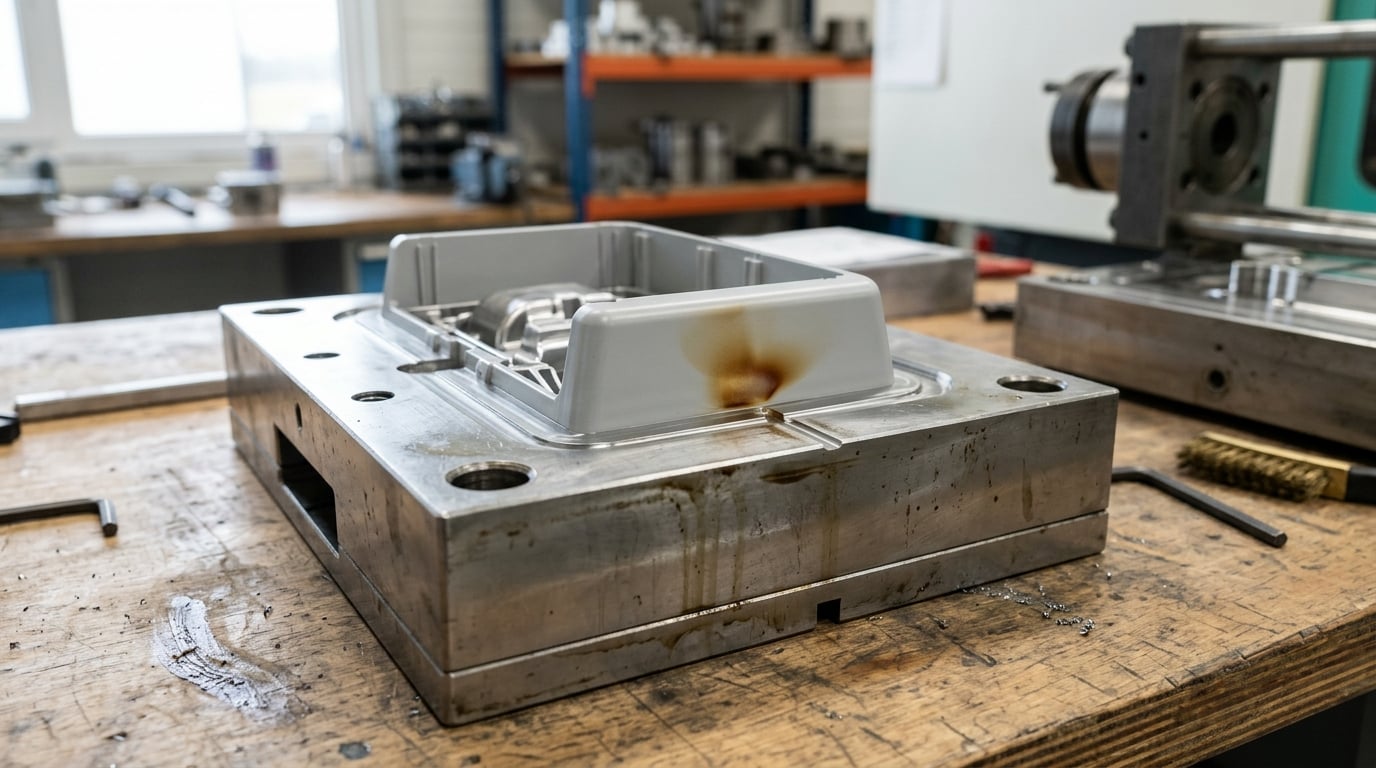
Venting problems in injection molds show up as burn marks, short shots, flow marks, flash at the vent, and weld lines that snap in your hand. Nearly all of them trace back to one thing: air that could not leave the cavity while plastic filled it. The fix is usually a vent, but the right vent, in the right place, at the right depth. Here is how to work from the part in your hand to the change that actually solves it. Updated for 2026.
Table of Contents
Venting Problems in Injection Molds: Symptoms and Quick Diagnosis
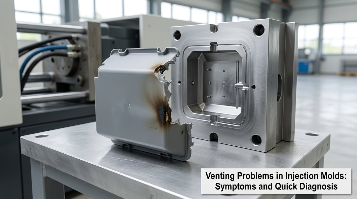
Mold venting is the set of shallow channels, pins and inserts that let trapped air and gas escape a closed cavity as molten plastic fills it. Air has to go somewhere, and when the mold gives it no cheap exit, it compresses ahead of the flow front, heats up, and fights the melt.
That gives you a short list of symptoms worth learning on sight.
Burn marks at the end of fill
A brown or sooty streak at the last point the part fills. Compressed air heats fast under injection pressure, and hot air next to hot melt ignites. Everyone calls it the diesel effect, though no diesel engine is involved.
Short shots that come and go
The part fills short on some cycles and not others, and the short edge is smooth where the flow front stopped. Trapped air builds back pressure the melt has to push through, and the pressure you have left may not be enough.
Flow marks and surface drag
A dull, rough or streaked patch trailing away from the last point to fill. Air in front of the flow front disturbs the skin of the melt, and that disturbed skin freezes before the cavity is packed.
Flash at the vent or parting line
Melt pushing out where gas is trying to get in. A vent that is too deep for the resin flashes first, which is the one symptom that means a venting problem in both directions.
Weld lines that snap in your hand
A visible line where two flow fronts met, with the surrounding material unable to take a load. Air left in the cavity stops the fronts fusing properly, and the knit’s strength drops well below the rest of the part.
Bubbles, voids and sink marks around them
Bubbles clustered near a thick section or the tail of the fill are trapped gas that froze into the part. Voids around them can turn into sink marks on the surface once the part cools and the void collapses.
Two habits speed this up. Look at where the defect sits relative to the end of fill, because that tells you where the air was, and check whether the defect repeats in the same place on every cavity. If only one cavity burns, suspect that cavity’s vent before you touch the process.
What Causes Venting Problems in Injection Molds?
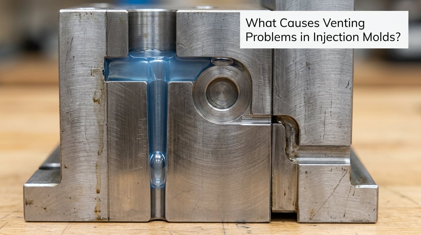
Venting problems fall into a handful of physical causes. Knowing which family you are in tells you whether to reach for the mold, the dryer, or the machine settings.
Vents that are blocked, too small, or in the wrong spot
A vent is an escape path with a size limit. Too small and the gas cannot leave faster than the cavity fills. Vents also go wrong by position: a spot vent on a plaque that has moved in a design revision is now venting a corner, not the end of fill.
Vents clog faster than most people expect. Mold release agent, ejector grease, pigment, and degraded resin oligomers all build up in a vent land and turn an open channel into a blind one. A mold that ran clean at trial can be under-vented fifty thousand shots later.
Gas that the mold never planned for
Resin that is wet gives off steam at melt temperature, and that is a much larger volume than the air a vent was sized for. Hydrolytic degradation, burnt material sitting in the barrel, and moisture in regrind or pigment all add gas that shows up as voids, splay, or burn marks far from any air trap.
Gate and runner geometry
A single gate at one end of a long part means the far end is filled last and vented worst. A runner that ends in a dead leg traps its own air. Multi-cavity layouts where the flow path length differs between cavities guarantee that at least some cavities vent worse than others.
Air trapped in thick sections
Ribs, bosses, and heavy sections create air traps the flow front wraps around but never fills. The rule of thumb is depth to wall thickness: a rib roughly one and a half times deeper than the wall it sits on tends to trap air, and ribs running perpendicular to flow trap worse than ribs along it.
Process settings that trap air
Excessive hold pressure or hold time squeezes gas back into the vent and can flash it. A short cushion leaves the screw recovering, which adds cycle time without helping fill. Very high injection speed gives the air no time to move. Warm mold in one area and cold in another changes the fill pattern from one shot to the next, so the end of fill moves and a vent that used to work no longer lines up with it.
Wear and damage to vent passages
High-cavity tools see more flow across the vent land than anyone planned for. Erosive wear, cavitation, and flash dressing during maintenance all change vent depth over time. Corner vents on plaque-style parts wear much faster than full-length perimeter vents.
How to Diagnose the Root Cause
Diagnose in an order that rules whole families out at once instead of changing one setting at a time by feel. I use this sequence on a running tool, and it has saved more time than any single piece of software.
Step 1: Find the end of fill for real
Run a short-shot study. Reduce shot size progressively until the part is roughly 50 percent filled, then step it up in increments until it is complete, and mark the end of fill on each sample. Doing this with the vents partly blocked makes the air traps visible as the actual bubble fronts in the melt.
Step 2: Map the defect against that end of fill
Compare your part to the short-shot map. A burn mark sitting exactly at the mapped end of fill is a venting problem, not a material or machine problem. A defect that moves between shots while the settings stay fixed usually points at temperature or fill-pattern instability instead.
Step 3: Block the vents in the machine and watch
This is the fastest shop-floor test there is, and almost nobody documents it. With the mold closed and hot, putty or tape over the suspect vents and run a few shots. If the burn mark fades or the fill improves, the air was coming through there and your vent is inadequate. If nothing changes, the gas is not leaving that area at all.
Step 4: Check material condition
Confirm dryer temperature, dew point, and residence time, and check moisture content if your supplier offers it. Then look at what the screw is actually doing: long residence time, high melt temperature, and regrind above about 10 percent are the usual gas generators nobody suspects.
Step 5: Read the pressure trace
On a machine with a cavity pressure transducer, venting is readable directly. A pressure trace that stays high right up to the end of fill says air is trapped and fighting you. A sharp drop as the cavity fills says gas left faster than the melt arrived, which usually means an oversized vent and possible flash.
Step 6: Inspect the vent passages
Look at the land depth with a depth gauge or microscope, not a caliper, and check the vent for release agent and grease film. Compare against the vent map on the drawing, because a design change that nobody documented is a common cause of a vent that no longer matches the geometry.
Step 7: Validate one change at a time
Change a single variable, run enough shots to see the trend, and record it. Two changes at once will teach you nothing, and venting problems get misdiagnosed for years because somebody raised injection speed and added a vent on the same trial.
| Symptom | Where it appears | Likely venting cause | What to check first |
|---|---|---|---|
| Burn mark or diesel effect | End of fill, last corner to fill | No vent, blocked vent, or vent too small for the fill rate | Vent depth, land length, and whether a vent exists at the end of fill at all |
| Short shot, intermittent | Whole part, rounded flow front | Gas back pressure, or wet resin generating steam | Dryer records, then vent capacity at the end of fill |
| Flow marks or matte surface | Trailing the end of fill | Disturbed melt skin from trapped air | Vent depth versus flash threshold for the resin |
| Flash only at the vent | Vent land, parting line near vent | Vent too deep for this resin and fill rate | Reduce depth toward the low end of the resin range, or add a flash trap |
| Weak or visible weld line | Where two fronts meet | Air not cleared before the fronts meet | Vent at or just past the weld line, plus flow front speed |
| Bubbles and voids near a thick section | Ends of ribs, tops of bosses | Deep rib or blind boss air trap | Depth-to-thickness ratio, and whether the trap has any vent path at all |
| Part sticks to the core, grease marks | Whole cavity, on opening | Vacuum inside the cavity, no reverse venting | Ejection force and vent depth on the parting line |
| Defect only in one cavity of eight | Single cavity, repeatable | That cavity’s vent differs or is obstructed | Compare vent depth cavity to cavity with a depth gauge |
| Venting fine at trial, failing after 50,000 shots | Gradual, whole tool | Vent land clogged with deposit or worn by flash | Clean the land and check the vent map against the drawing |
Two rules of thumb that circulate in the industry are worth dropping early. Venting the cold well opposite the sprue is usually unnecessary, because the ejector pin slip fit already moves the air. And venting the runner only makes sense when the runner’s air volume is a meaningful share of the mold’s total air volume, which is rarely true on a short-runner, low-cavity tool.
How to Fix Venting Problems
Fixes fall into three buckets, and the order you try them matters because a mold change costs far more than a settings change.
Mold work: place and size the vent correctly
Put the vent at the end of fill, not near the gate, and on the surface the air pushes against last. Make the vent land long enough to build a solid freeze seal behind it, and put a deeper relief channel at the far end of the land so the vent does not simply fill up with frozen plastic after the first shot.
Vent depth is set by the resin, because what you are balancing against is the flash threshold. Semi-crystalline materials and stiff engineering resins can hold a deeper land than amorphous ones, which flash at a much smaller land depth.
| Resin family | Vent land depth | Typical notes |
|---|---|---|
| PE, PP | Around 0.015 to 0.025 mm (0.0006 to 0.001 inch) | Wide, forgiving range; start shallow if the part is cosmetic |
| ABS, PS, PC | Around 0.010 to 0.020 mm | Flash early, so favor a longer land over a deeper vent |
| PA and other filled engineering grades | Around 0.005 to 0.015 mm | Filler raises flash risk and adds its own wear to the vent steel |
| POM | Shallow end of the range | Marks easily and is unforgiving of a too-fast vent |
These are shop ranges, not tool-room tolerances, and they shift with fill rate and resin grade. Run a short-shot study to confirm rather than trusting a chart over your own part.
When a shallow land flashes, the answer is a longer land or a flash trap, not a deeper vent. A flash trap lets you use a vent two to three times deeper than the resin’s normal flash threshold, because the melt that flashes is diverted into a channel that fills solid and seals.
Vent methods and where each one belongs
Parting-line vents handle the end of fill on most flat parts. Vented ejector pins reach spots a parting-line vent cannot, such as the tip of a blind boss. Core inserts with a natural vent at their outer diameter handle deep ribs where a pin would weaken the rib.
| Method | Best use | Upfront cost | Maintenance reality |
|---|---|---|---|
| Parting-line vent with land and relief channel | End of fill on plaque and housing parts | Low | Inspect at scheduled tool maintenance; clean the land, keep the relief clear |
| Vented ejector pin | Ends of ribs, blind bosses, corners the parting line misses | Low to medium | Prone to clogging; self-clearing pin types shed deposit as they open and close |
| Core insert with natural vent | Deep ribs and thin sections that a pin would weaken | Medium | Land wears with the insert; harder to reach without partial disassembly |
| Porous sintered steel insert | Gas-heavy applications, optical parts, high gas rates | High | Cannot be machined to fix; usually replaced rather than cleaned |
| Vacuum-assisted venting | Deep cores and blind cavities no open vent can reach | High, plus machine support | Added equipment to maintain; solves cases a vent cannot |
Material work
If gas is coming from the resin rather than from the cavity air, no vent depth will save the part. Fix the dryer, cut regrind, drop the back barrel zone, and shorten residence time. Vent depth and material conditioning go together, and changing both at once is how a good diagnosis gets thrown away.
Process work
Lower hold pressure and hold time so gas is not pushed back into the vent. Slow the final stage of fill enough that the flow front stays ahead of the air it displaces, without extending the cycle more than the process can absorb. Balance mold temperature across the cavity, because an unbalanced mold moves the end of fill shot to shot. Leave a cushion the machine can recover from; a screw that never returns is wasted cycle time.
As a rough sizing target, total vent area across the mold is commonly taken as at least 30 percent of the gate cross-sectional area. Parts with heavy outgassing or long flow paths need more, not less.
Venting Problems in Injection Molds: Process vs. Design Issues
Most frustrating venting calls are not venting calls at all. The useful question is whether a setting change can fix it or the tool has to come apart, and you can usually answer that before touching anything.
| Signal | Process-side problem | Design-side problem |
|---|---|---|
| End of fill | Moves shot to shot; tied to mold temperature or speed settings | Fixed by geometry; the same spot every cycle |
| Improves when a vent is blocked with putty | Unlikely, since blocking removes escape capacity | Strongly indicates the vent is undersized or missing |
| Defect present at trial and steady state | Settings were never right, or were never validated | Design never had a vent where the air went |
| Onset after thousands of shots | Material outgassing or a dirty vent land | Vent steel wear and progressive clogging |
| Only some cavities affected | Cavity-to-cavity fill difference, usually temperature | Vent differs between cavities, or an obstructed path |
| Responds to hold pressure changes | Almost certainly process-side | No real response, because the gas is not venting at all |
Process-side problems are cheap to test. Change one setting, run a few hundred shots, and look at the trend. If the defect does not move, stop adjusting the machine and go to the mold.
Design-side problems need tooling. A missing vent, a vent sized for a flow path that no longer exists, a rib too deep to vent through its own tip, or a gate that forces a long single-ended fill are all engineering changes with lead time. The sooner you identify one, the earlier it can go into the next tool revision instead of becoming a permanent workaround of higher pressure and longer cooling.
A related failure deserves its own mention. When the cavity goes from sealed to cooling, the gas inside contracts and pulls a vacuum against the core, and the part can stick or draw grease back through the vent. Leaving a slight reverse vent at the parting line lets air in on opening, breaks the vacuum, and cuts ejection force. If parts are sticking at the end of a vent, that adjustment usually costs nothing and often fixes it outright.
How to Prevent Future Venting Failures
Preventing this is mostly record-keeping and inspection, which is the part most shops skip. A vent that worked at trial is not evidence about the vent at 500,000 shots.
Put the vent map on the drawing, not in a technician’s head. Every vent gets a number, a location, a land depth and a land length, and that map travels with the tool. When a defect appears, the map turns guesswork into a short inspection.
Schedule vent inspection the way you schedule ejector pin checks, on a cycle interval rather than on failure. A reasonable starting point is every 50,000 to 100,000 shots for high-cavity tools, shorter for cosmetic or optical parts where a vent mark shows up on the finished product. At the same interval, measure land depth at a marked point on each vent so wear shows up as a number instead of as a complaint.
Control what reaches the vents. Release agent overspray and ejector grease are the two most common clogging deposits, and both are process habits rather than mold faults. Clean the land with a brass brush and a non-residue solvent, and clean relief channels while you are there, because a clogged relief channel fails the same as a clogged land and gets missed far more often.
Validate vents during mold trial, not after. Fill a cavity to 50 percent, 75 percent, and full with the vents in their final condition, and confirm that the end of fill sits where the vent map says it will. A part that looks fine on the first shot can have a vent that only works for the first ten.
Treat design changes as vent changes. A rib shortened from 20 mm to 12 mm changes the air trap, and a gate moved to the opposite end changes the end of fill. A mold flow analysis in Moldflow or Moldex3D before the steel is cut will flag air traps that no short-shot study will find until the tool is built and running.
Frequently Asked Questions
Where should vents go in an injection mold?
Vents go where the air ends up, which is the end of fill, plus any weld line and any deep rib or blind boss where the flow front wraps around trapped air. Find the end of fill with a short-shot study rather than guessing from the CAD. On plaque and housing parts a parting-line vent at the far end from the gate is the usual answer. Venting the cold well opposite the sprue is a common rule of thumb that most tools do not need.
How deep should injection mold vents be?
Vent land depth is set by the resin’s flash threshold, not by how big the trapped air is. Most shops run 0.015 to 0.025 mm for PE and PP, shallower for ABS, PS, PC, and considerably shallower for filled engineering grades and POM. When a shallow land flashes, lengthen the land or fit a flash trap rather than deepening the vent, because a deeper vent just moves the flash further into the vent.
What is a home-plate vent and when is it used?
A home-plate vent is a vent land with a wider section at one end, giving gas a larger area to escape into while the land still freezes solid and seals the cavity. It is used where fill rates are high or gas volume is large, such as on Class A cosmetic surfaces, optical parts, and long flow paths. The wider end sits beyond the end of fill, and the narrow land sits between it and the cavity so the seal forms at the same point every shot.
Do I need to dry the resin to fix venting problems?
Dryness matters whenever gas is generated rather than merely displaced. Wet resin produces steam at melt temperature, and steam expands far more than trapped air, so a vent sized for air can still be overwhelmed. A vent fix will hold for a while and then drift back as the cycle count climbs. Check the dryer temperature, dew point, and residence time before changing any vent depth, and revisit drying whenever the defects change character between batches.
Can venting cause flash?
Yes, and it is one of the more confusing symptoms because the same feature causes both the short shot and the flash. A vent deeper than the resin can hold allows melt to push out at the parting line, and the flash that forms then clogs the vent, so the tool gets worse every cycle. Shrink the land depth toward the shallow end of the resin range, lengthen the land, or add a flash trap that lets you use a deeper vent without letting the melt escape.
Start with the end of fill. Run the short-shot study, block the suspect vents with putty, and see whether the defect moves. If it does, the mold is telling you exactly where the gas is, and you can size a vent for that spot. If it does not, the gas is coming from the resin or the process, and no vent depth will fix it.