
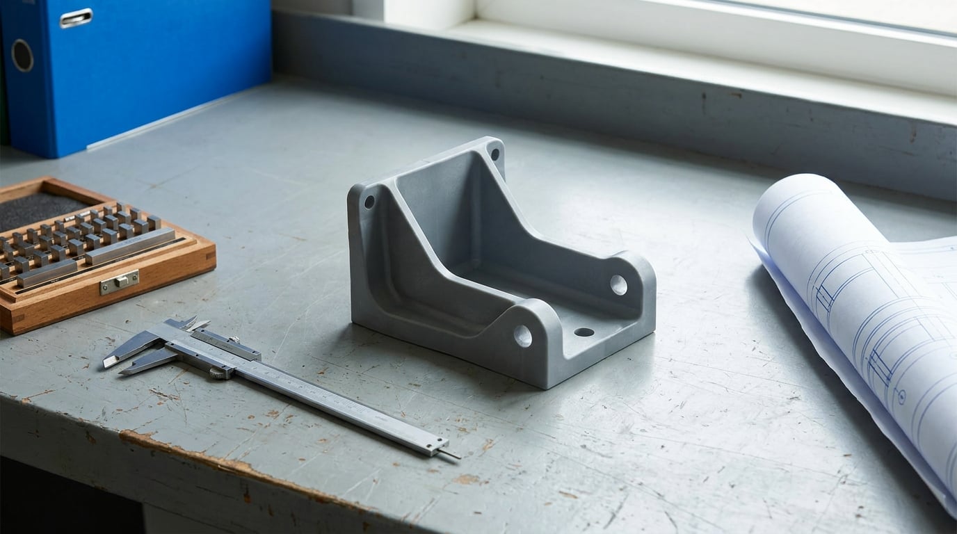
Plastic part tolerance standards are published documents that set out how far a molded plastic part may deviate from its nominal dimensions and still count as acceptable. The primary international reference is ISO 20457, DIN 16901 is its long-serving European predecessor, and ASME Y14.5 supplies the geometric tolerancing symbols used alongside them. This guide covers what each standard governs, which tolerance classes molded parts can actually hold, and how to write the callouts so a toolmaker and a buyer mean the same thing.
Table of Contents
- What Are Plastic Part Tolerance Standards?
- Which Tolerance Standards Apply to Plastic Parts?
- How Do General and Dimensional Tolerances Work?
- How Should a Plastic Part Drawing Express Tolerances?
- Why Do Plastic Tolerances Behave Differently by Process?
- How Do Material Shrinkage and Service Conditions Affect Tolerances?
- How Are Plastic Part Tolerances Inspected?
- When Should a Part Use Tighter or Looser Tolerances?
- Frequently Asked Questions
- What is the standard tolerance for molded plastic parts?
- Are ISO 294 and ASTM D667 tolerance limits the same?
- How tight can injection-molded plastic parts be?
- Should plastic part dimensions be measured immediately after molding?
- How many samples should be checked for plastic part tolerances?
- Can a CNC-machined feature hold tighter tolerances than a molded feature?
- Conclusion
What Are Plastic Part Tolerance Standards?
Plastic part tolerance standards are published documents defining the permitted dimensional and geometric variation for molded plastic parts. ISO 20457 is the main international standard and DIN 16901 is its widely used European predecessor. They assign general tolerance classes by nominal size and set the acceptance conditions, including conditioning time before measurement, under which a part conforms.
A nominal dimension is the number in the middle of the range. A tolerance turns it into two limits, one above and one below, and the part is judged against those limits rather than against the nominal. A 30.00 +0.3/−0.1 mm dimension accepts anything from 29.90 to 30.30 mm. Nothing in that band is off-spec, including the extremes, which is exactly why a tolerance is a design decision and not a rounding rule.
Standards exist for three reasons. First, interchangeability: two parts from two different tools, or two different plants, have to fit each other. Second, inspection: a buyer and a supplier need one shared number rather than two opinions. Third, cost. A tighter tolerance raises tool cost, cycle time, inspection effort and scrap, so every tightened number has to justify itself against the function of the feature.
That last point matters more for plastics than for metal. Thermoplastics typically shrink between 0.3% and 3% as they cool in the mold, and the result moves with mold temperature, wall thickness, packing and even the season of the year. A tolerance written without a standard behind it is a guess, and a guess that is tighter than the process can hold is expensive.
How plastic part tolerance standards differ from metal machining standards
Metal parts are machined subtractively from material that does not meaningfully change size between the moment it is cut and the moment it is measured. Molded parts are formed while the material is hot, viscous and shrinking the entire time. A steel part that measures 20.02 mm at the machine will still measure 20.02 mm on the bench in January. A polycarbonate part can move between the tool and the assembly floor.
Two habits carry over from machining and cause trouble. The first is specifying to a number without asking what the mold can hold. The second is confusing the part dimension with the cavity dimension. The toolmaker builds the cavity oversized, by the material’s shrink rate, so that the molded part lands on the number you want. Drawings must therefore always specify part dimensions, never cavity dimensions.
Metals also tend to fail gracefully. A slightly undersize shaft in steel is still a shaft. A slightly undersize snap-fit rib in a polycarbonate latch is a broken latch, because plastics concentrate stress at thin sections. Geometry and material behaviour interact, and a tolerance that would be trivial on a metal part can be structural on a molded one.
Which Tolerance Standards Apply to Plastic Parts?
ISO 20457 governs tolerances and acceptance conditions for plastics moulded parts, DIN 16901 is its European predecessor, ISO 29469 covers machine-related tolerances for injection and rotational molding machines, and ASME Y14.5 (identical in content to ISO 5459) supplies the geometric tolerancing symbols applied alongside them.
| Standard | Publisher | What it governs | Where you see it |
|---|---|---|---|
| ISO 20457 | ISO | Dimensional and geometric tolerances for plastics moulded parts, general tolerance classes by nominal size, and acceptance conditions | Global drawings, purchasing specifications, supplier quality agreements |
| DIN 16901 | DIN (Germany) | The predecessor document to ISO 20457, with the same general tolerance concept and the conditioning rule before measurement | Legacy European drawings still in circulation on older programs |
| ISO 29469-1 and -2 | ISO | Machine-related tolerances for the injection unit and the clamping unit of molding machines | Machine specification sheets and plant procurement, never part drawings |
| ASME Y14.5 | ASME | Geometrical tolerancing: datum reference frames, flatness, profile, position, and the feature control frame symbols | Any drawing that calls out datums or geometric controls |
| ISO 5459 | ISO | The international counterpart to ASME Y14.5, with the same concept and broadly the same symbols | Non-US drawings, or global programs wanting one symbol set |
| ASTM D667 | ASTM (US) | Dimensional tolerances for thermoplastics molded parts, US practice for thermoplastics specifically | North American drawings citing an ASTM standard |
Two things to note about the table. ISO 29469 is regularly mistaken for a part tolerance standard, but it covers the molding machine’s own units, not the parts coming out of them. And the geometric standards do not set numbers of their own; they tell you how to control a feature, while ISO 20457 or your drawing note supplies the limits.
ISO 20457 has been revised over the years, and the edition matters. Drawings in the wild still reference the 2018 edition, the 2003 edition, and DIN 16901. The conceptual framework has not changed much, but the size bands and class values were reorganized, so when you compare a drawing against a standard, compare edition against edition rather than assuming the numbers transfer. Pin the revision in writing on the drawing or in the purchase order.
Material and process specifications supplement dimensional standards rather than replacing them. A resin datasheet tells you the molding shrink rate and the specific gravity, which is what the toolmaker needs to size the cavity. It does not tell you what variation to accept on the finished part. The same is true of ISO 29469 for the machine, and of internal capability data such as Cpk, which describes the process you actually have rather than the process the standard imagines.
How Do General and Dimensional Tolerances Work?
A general tolerance is a class applied to every dimension on a drawing that does not carry a specific tolerance. The drawing says something like ISO 20457-MG, and every untoleranced linear dimension inherits that class according to its nominal size. This is what keeps plastic drawings readable. A housing with forty features does not need forty limit pairs, only the four or five that actually control function.
Specific tolerances override the general note, and they belong on the features where variation changes assembly or performance. The rule of thumb I use is simple: if loosening the limit would let the part fail, wear, or leak, it gets a specific tolerance. If it would only look different, it stays general.
| Nominal size (mm) | Tight class | Moderate class | Loose class |
|---|---|---|---|
| 0 to 10 | ±0.05 mm | ±0.10 mm | ±0.20 mm |
| 10 to 30 | ±0.10 mm | ±0.20 mm | ±0.30 mm |
| 30 to 120 | ±0.15 mm | ±0.30 mm | ±0.50 mm |
| 120 to 400 | ±0.30 mm | ±0.60 mm | ±1.00 mm |
| 400 to 1000 | ±0.50 mm | ±1.00 mm | ±1.50 mm |
These are the ranges I use for early planning, and they sit in the same territory as the published general tolerance classes. Treat them as a starting point, not a substitute for buying the standard and working from its actual table. One published tolerance class on rotational molding is far looser than the table above, and quoting a general tolerance for a process that cannot hold it guarantees a dispute at incoming inspection.
| Metric | Inch equivalent | Metric | Inch equivalent |
|---|---|---|---|
| 0.05 mm | 0.002 in | 0.30 mm | 0.012 in |
| 0.10 mm | 0.004 in | 0.50 mm | 0.020 in |
| 0.15 mm | 0.006 in | 1.00 mm | 0.039 in |
| 0.20 mm | 0.008 in | 1.50 mm | 0.059 in |
Tolerance types differ by what they control. Linear tolerances govern straight-line distances between features. Angular tolerances govern the angle of a face or draft, usually stated in degrees, and a half-degree error on a 100 mm deep cavity moves the base of the wall enough to matter. Profile tolerances govern the whole outline of a surface, which is the right choice for anything that seals or slides. Radius tolerances matter because molded corners and drafted edges almost never match the theoretical sharp corner, and treating a fillet as a sharp corner is a common drawing error.
Bilateral, unilateral and project tolerances set the limits differently. Bilateral means limits either side of nominal, the normal case. Unilateral puts all the variation on one side, which is how you guarantee a minimum wall thickness, a minimum boss diameter or a clearance fit without an interference risk. A project tolerance, sometimes called a resultant or virtual condition tolerance, applies when two features mate: the tolerance is written on the size of one feature and a modifier ties it to the other, and the inspector must check the assembled condition rather than the two parts separately.
Datums make any of this meaningful. A tolerance with no reference is a floating tolerance, and it is a poor inspection instruction because the measurement method decides the result. A datum reference frame fixes the part in a repeatable way, usually a large moulded pad or a machined flat, and then the controlled features are dimensioned from it. Without a datum, two inspectors on the same part can differ by more than the tolerance they are both checking.
How Should a Plastic Part Drawing Express Tolerances?
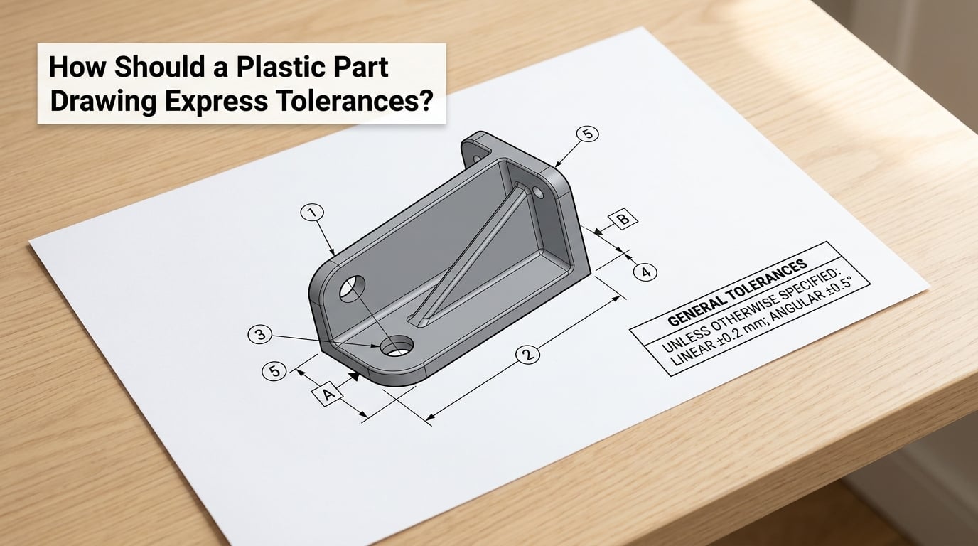
A well-drawn plastic part puts the general tolerance note in the title block area, dimensions the functional features from a defined datum, and gives specific limits only where variation changes how the part works. Get those three things right and most of the arguments between engineers and suppliers never start.
The general tolerance note is the single most useful block on a molded drawing. A workable version looks like this, and the parts that matter are the standard plus class, the material grade, and the units:
| Line | Example | Why it is there |
|---|---|---|
| General tolerance | ISO 20457-MA | Sets the class applied to every untoleranced linear dimension |
| Units | mm | Prevents an inch-millimetre dispute at inspection |
| Material | PC/ABS, unfilled, specific grade | Fixes the shrink rate the tool must compensate for |
| Conditioning | Measure after 16 h at 23 °C and 50 % RH | Matches the acceptance conditions in the standard |
| Surface | As molded, no cosmetic specification | Stops texture expectations being written as dimensions |
| Drawing scale | Do not scale drawing | Stops a scaled print being used to set a limit |
Place every dimension on one view of the part rather than scattering them across several. Repeat a dimension only when the geometry makes that unavoidable, and flag the repeat as reference. Give the function-defining features, the hole and boss pairs, the sealing faces, the bearing bores, and anything that locates another part, their own explicit tolerances. Everything else inherits the general class.
Choose datums that reflect how the part is actually located in the assembly and how it will be fixtured during inspection. The best datum is a large flat pad that a gauge can sit on without a fixture, and it is usually the same feature that establishes the part in the next assembly. Datum schemes that look rigorous on paper but cannot be physically located on the real part produce unmeasurable drawings.
One more habit pays off: state the tolerance with a limit rather than a plus-minus when a minimum matters. A minimum wall of 1.2 +0.1/−0 mm guarantees the design intent, while 1.2 ±0.05 mm allows a 1.15 mm wall that may not fill. Minimums are free; maximums are what kill parts.
| Feature | Specific tolerance? | Reason |
|---|---|---|
| Hole to mating boss clearance | Yes, specific | Controls assembly force and wear; this is the classic stack |
| Snap-fit cantilever thickness | Yes, unilateral minimum | Sets the engagement force directly |
| Sealing face flatness | Yes, geometric | A surface profile limit, not a linear one |
| Cosmetic rib spacing | No, general | Variation is invisible to function and adds cost |
| Draft on a non-sealing wall | No, general or noted only | Draft is a moldability requirement, not a fit control |
| Overall envelope length | Usually no | Only matters if it enters a cavity or a stack |
Why Do Plastic Tolerances Behave Differently by Process?
Each molding process limits accuracy in a different way, so the achievable tolerance is a property of the process as much as of the material. Injection molding holds the tightest numbers because the cavity is rigid steel under pressure. Rotational molding is loose because a free-rotating shell cools from the outside in. Additive processes sit in between and add their own artefacts, and CNC-machined plastic holds tighter than any molding process because the machine is doing the finishing.
| Process | Typical part tolerance | Main distortion risk | What tightening costs |
|---|---|---|---|
| Injection molding | ±0.05 to ±0.3 mm on features | Differential cooling causing warpage and sink | Longer hold and cooling, tighter cavity machining, more inspection |
| Compression molding | ±0.1 to ±0.4 mm | Thickness variation and flash at the parting line | Die finishing and press tonnage, less flexibility on wall thickness |
| Rotational molding | ±3 to ±5 mm on large parts | Cooling rate, wall thickness variation, warping on demolding | Long cycle times; a published factory standard is ±5 mm for sizes to 1000 mm |
| CNC-machined plastic | ±0.01 to ±0.05 mm | Setup error and stress relaxation in the workpiece | Higher machining time per part and scrap risk on filled grades |
| Additive manufacturing | ±0.1 to ±0.3 mm typical, better on resin systems | Layer build-up, anisotropy, thermal distortion | Slow build, support removal, and limited material choice |
Rotational molding is the clearest illustration of why the process matters. A published supplier standard for most rotomolded products is ±5 mm for sizes up to 1000 mm, and one factory has documented a customer request of ±0.5 mm against its own achievable limit of ±0.8 mm. That is not a failure of effort. A rotomolded part is a hollow shell that cools on all sides at once, and its wall thickness is set by powder deposition, not by steel, so ±0.5 mm is asking the process to control something it cannot control.
Injection molding sits at the other end. Suppliers describe all-electric servo machines with position accuracy around ±0.1 mm, pressure detection down to 0.1 bar and a control loop of a few milliseconds as the entry point to sub-0.01 mm repeatability, with core flatness held below 10 µm. Those are machine figures, not part figures. A machine that repeats to 10 µm still produces a part with 0.3% shrink variation across its wall, and the cavity compensation for that shrink is where most of the actual dimensional error comes from.
How to reduce shrinkage during injection molding
Shrinkage is reduced at the tool, the part, and the process window, in that order of leverage. Changing the machine is the last resort.
- Make the wall thickness uniform. Differential thickness is the single largest source of variable shrink; a 2.5 mm wall next to a 4 mm rib core will always pull differently than the 2.5 mm wall does on its own.
- Size ribs at roughly half the nominal wall, so the core thickness in the rib stays close to the surface thickness and cools at a similar rate.
- Place the gate so the flow front advances symmetrically around the cavity. Off-centre gates cause the far side to pack differently from the near side.
- Settle hold time and hold pressure as a pair. Hold pressure sets the packed weight, and hold time sets whether the gate has frozen or not; too little of either, and the part is under-packed and shrinks beyond expectation.
- Balance the cooling circuits so both halves of the cavity reach temperature together. Unbalanced cooling shows up as warpage long before it shows up as a dimensional error.
- Control mold temperature. It is often the largest single contributor to repeatable part size, and it is also the easiest parameter to vary unintentionally between a warm summer start-up and a cold night shift.
- Build shrinkage compensation into the cavity size and verify it on a first article before cutting steel assumptions into the drawing.
How Do Material Shrinkage and Service Conditions Affect Tolerances?
Mold shrinkage is the difference between the cavity size and the finished part size, expressed as a percentage. A resin that shrinks 0.6% in a 2 mm wall shrinks a 50 mm feature by roughly the same percentage, which is 0.3 mm. The toolmaker compensates by cutting the cavity 0.6% oversized. The tolerance on the drawing, though, is about the part, not about how precisely the steel was cut.
| Material | Typical shrink rate | Notes for tolerancing |
|---|---|---|
| ABS | 0.4 to 0.9 % | Moderate and consistent; a good general choice for tight features |
| Polypropylene | 1.5 to 2.5 % | High for a commodity resin; filled grades shrink less than unfilled |
| Polycarbonate | 0.5 to 0.7 % | Low and stable, but sensitive to weld lines and moisture |
| PA6 nylon | 0.8 to 2.0 % | Hygroscopic; dimensions move with moisture uptake after molding |
| POM acetal | 1.8 to 2.5 % | High shrink and long crystallisation; allow for post-molding growth |
| PVC-U rigid | 0.1 to 0.5 % | Very low shrink, but sensitive to processing history |
| HDPE | 1.5 to 2.5 % | High shrink and creep; not suited to close fits |
| PSU | 0.5 to 0.7 % | Low shrink, high residual stress, warpage-prone if cooled unevenly |
| PEEK | 1.0 to 2.0 % | Enabling engineering resins, still not metal-class accurate |
Unfilled and glass-filled grades of the same resin are different tolerance problems. Filler reduces shrink and adds stiffness, but it introduces fibre orientation: the flow direction, the thickness direction and the transverse direction each shrink differently. A dimension measured parallel to the flow can be inside tolerance while the same dimension measured across the flow is not. That is why a filled grade does not automatically buy you a tighter class, only a more directional one.
Three dimensions matter and they are not the same number. The nominal dimension is what the drawing calls for. The molded dimension is what comes out of the tool after accounting for shrinkage. The in-service dimension is what the part measures at its actual operating temperature, after absorbing whatever moisture the material takes up and after whatever creep has occurred. In most programs the drawing is written to the molded dimension under defined conditioning conditions, and the in-service variation has to be absorbed by the design.
Differential shrinkage is the harder case. A thin rib and a thick boss in the same part cool at different rates, so a nominal 1.0 mm shrink rate is not a number you can apply uniformly. Uncontrolled differential shrink shows up as a cracked weld line, a twisted flat panel, or a dimension that is in spec at the gate and out of spec at the far end of the flow path.
Service conditions then add a second layer. The coefficient of thermal expansion for a glass-filled engineering resin is roughly a quarter to a third that of steel, so a 200 mm part moving through a 50 °C change shifts dimensionally in a way that surprises people coming from metal. Hygroscopic resins keep changing for days after molding as they take up moisture, and the conditioning rules in the standards exist precisely because of this.
Seasonality is not a rounding error either. One rotomolding plant reported that parts demolded in winter warped far more than the same product in summer because the unmolded shell cooled faster, with the foaming step stretching from about 20 minutes in summer to 2 hours in winter, forcing them to add more than ten extra molds just to hold labour cost. Their published tolerance is generous by design, and the reason is a season, not a machine.
How Are Plastic Part Tolerances Inspected?
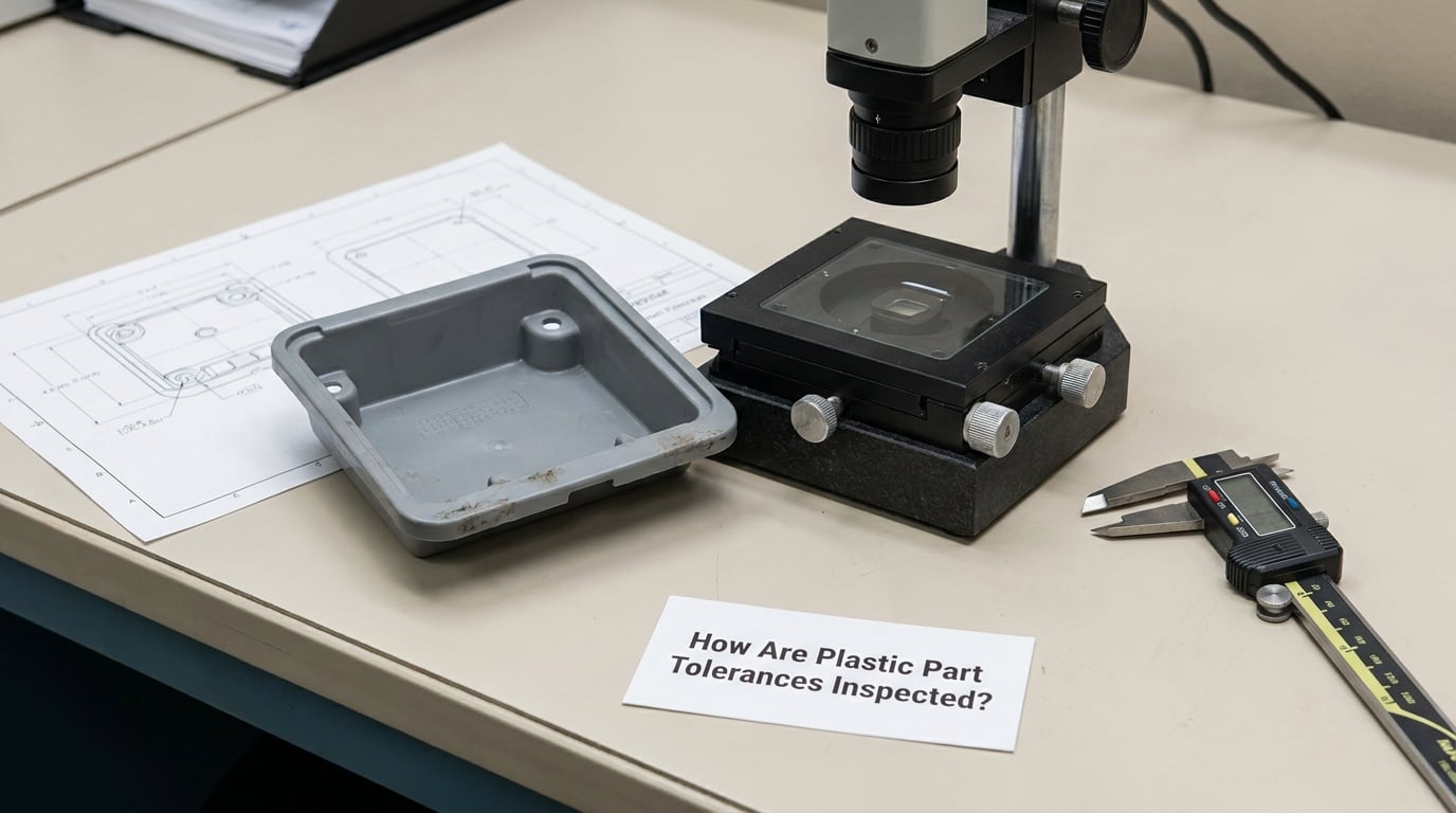
Inspecting plastic tolerances is mostly about matching the equipment to the tolerance and conditioning the part to the standard’s acceptance conditions before anyone touches a gauge. A caliper cannot judge a ±0.05 mm limit, and a part measured hot off the machine is not the part the standard is talking about. The conditioning requirement in ISO 20457 and DIN 16901 of at least 16 hours at a controlled temperature and humidity exists for this reason.
The governing rule is that measurement uncertainty should be no more than roughly a tenth of the tolerance you are checking. A caliper with 0.02 mm resolution on a ±0.05 mm tolerance consumes most of the window in gauge error alone, and the reading becomes an argument rather than a measurement. Where the tolerance is tight, the equipment has to be a micrometer, an optical comparator, a blue-light or structured-light scanner, or a coordinate measuring machine.
| Tolerance size | Suitable equipment | Typical approach |
|---|---|---|
| ±0.5 mm and looser | Caliper, tape, height gauge | 100 % check possible, low measurement cost |
| ±0.1 to ±0.5 mm | Vernier, micrometer, dedicated fixtures | Sample checks with go and no-go gauges |
| ±0.05 to ±0.1 mm | Micrometer, optical comparator, scanner | First article plus periodic SPC sampling |
| ±0.05 mm and tighter | CMM, scanner with validated capability | First article and periodic capability studies only |
Attribute and variable inspection are two different ways to judge the same limit. Variable inspection records a measured value and computes statistics; it is what you want when you need to know whether the process is centred and capable, and it is how Cpk numbers come from. Attribute inspection simply asks pass or fail using fixed gauges; it is cheaper, it protects the line, and it tells you nothing about whether you are drifting toward failure.
Process capability is the summary measure. Cp compares the width of the tolerance to the spread of the process, and Cpk also accounts for where the process sits inside that tolerance. A process whose distribution just fits inside the limit is not capable in any useful sense, because a small shift in material batch or ambient temperature pushes parts out. Most quality teams ask for a Cpk of 1.33 or better on critical dimensions, and require it demonstrated on production tooling rather than on a prototype.
Sampling should follow risk. Checking every part on a critical snap-fit dimension can be worth it when failure means a returned product. Checking every part on a cosmetic rib is waste. A workable plan is 100 % go and no-go gauging on critical features at the line, a measured first article with full CMM data before release, and periodic variable sampling for capability trending. Whatever the plan, state the conditioning period, the measurement method and the reporting format on the purchase order, or the quotes you receive will not be comparable.
When Should a Part Use Tighter or Looser Tolerances?
Tighten a tolerance when the function demands it, and loosen it everywhere else. A tolerance is justified by a consequence: interference in an assembly, a leak, a stress riser that will crack in service, a clearance that a tolerance stack eats. A tolerance justified only by the fact that metal drawings usually carry one is a copied number, and copied numbers are where cost and scrap come from.
Stacking is where realistic values show themselves. Take a three-part stack: 20.00 ±0.10, 15.00 ±0.10 and 5.00 ±0.05. Worst-case arithmetic gives 40.00 ±0.25 mm, and every part in that stack must be at its worst limit simultaneously for the gap to fail. Statistical stacking with a process distribution instead gives roughly ±0.13 mm, which is why production parts often work when the drawing appears to say they should not. The trap is mixing the two: if a supplier quotes statistical while your design assumed worst-case, the assembly fails at end of line, not at the bench.
When a stack is too tight, the answer is usually design rather than metrology. A snap-fit can be made more tolerant by adding a lead-in chamfer, a ramp, or a compliant hook. A locating feature can carry a draft angle that self-centers it. A clearance fit can be opened up and still hold the function, because the load path is carried by a shoulder rather than by the clearance. Each of these buys more real-world margin than tightening the drawing ever would.
Tighter tolerances also cost money in specific places. The cavity steel has to be ground rather than spark-eroded, which is where most of the tool cost difference appears. Cycle time goes up because hold and cooling times extend to control the part. Inspection moves from a go gauge to a scanner or a CMM, and possibly to 100 % check. Lead time extends because the first article is no longer the first attempt. None of this is hidden from a good supplier, but it is rarely in the quote, which is why a tolerance discussion belongs before the tool is cut.
One last practice: never specify a tolerance tighter than the process is capable of, and never let a general note do the work on a feature that matters. Those two failures look identical on the shop floor, one part returned at a time.
Frequently Asked Questions
What is the standard tolerance for molded plastic parts?
For general molded parts, ISO 20457 assigns tolerances by nominal size band and tolerance class rather than giving one universal number. In practice, tight work lands near ±0.05 mm on features under 10 mm and ±0.1 to ±0.3 mm on features between 10 and 120 mm, with moderate and loose classes widening from there. Always state the standard and class on the drawing, and confirm the process can hold the class you choose before you release it.
Are ISO 294 and ASTM D667 tolerance limits the same?
No. ISO 294 was the international standard for thermoplastics moulded parts, and ASTM D667 is the US practice for thermoplastics molded parts; their size bands and class values were not identical. Both have since been superseded for most work by ISO 20457, which is the document to reference on a new drawing. Legacy drawings still citing ISO 294 or D667 are not wrong, but the numbers do not transfer cleanly between the documents.
How tight can injection-molded plastic parts be?
Most production injection molded features hold around ±0.1 to ±0.3 mm without difficulty, and roughly ±0.05 mm is achievable on smaller features with good mold flow and tight control. That is a part figure, not a machine figure. Electric servo molding machines repeat to about 10 µm at the platen, but part accuracy is still limited by shrink variation across the wall, so tightening beyond about ±0.05 mm usually needs a tighter resin, a better tool, or a machined feature.
Should plastic part dimensions be measured immediately after molding?
No. ISO 20457 and its predecessor DIN 16901 require measurement under defined acceptance conditions, generally after at least 16 hours of conditioning at controlled temperature and humidity. A part measured straight off the machine is still hot and still relaxing, so its dimensions are not the dimensions the standard is written about. Measuring too early gives readings that drift afterwards and leads to false rejections, or worse, false acceptances on the near side of the window.
How many samples should be checked for plastic part tolerances?
Match the sample to the risk. Use 100 % go and no-go gauging on critical features where failure means a returned product, a full measured first article with CMM data before production release, and periodic variable sampling to track Cpk on the characteristics that drive complaints. Sample sizes quoted from an arbitrary AQL are less useful here, because molded part variation is dominated by tool condition, cavity and material batch rather than by random unit-to-unit noise.
Can a CNC-machined feature hold tighter tolerances than a molded feature?
Yes, routinely. A CNC-machined feature in plastic commonly holds ±0.01 to ±0.05 mm, against roughly ±0.1 to ±0.3 mm for the same feature molded, because the machine removes material to size rather than relying on a cooling process. The trade is cost and time, and a machined feature left in a molded part can read as a design mistake. If you need one tight feature, machining it separately and inserting or overmolding it is often the cheapest route to accuracy.
Conclusion
Before releasing a plastic part drawing to production, do four things. List the features that actually control fit or function and give those explicit limits; leave the rest to a stated ISO 20457 general class with the edition pinned. Confirm the material grade and its shrink rate, since that is what sets the toolmaker’s compensation and what makes the in-service dimension different from the molded one. Check the process can hold the class you wrote, using capability data from production rather than a prototype. Then validate the inspection plan: measurement method, equipment capability against the tightest limit, conditioning period, and sample size, agreed before the first shot rather than after the first rejection.