
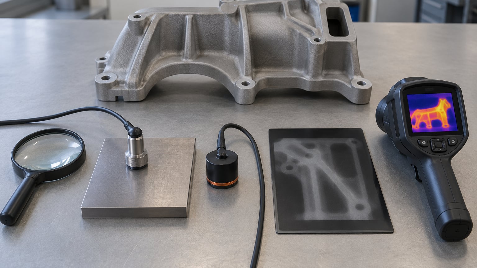
Non destructive testing methods compared: visual inspection is fastest, ultrasonic testing reaches deepest, and eddy current testing is quickest on conductive parts. Radiography shows you the internal picture directly, and thermography covers large surfaces without touching them at all. No single method wins every job, and the right pick comes down to the flaw you expect, the material, and how much access you have.
I have watched this argument play out on shop floors and in inspection reports for years. The mistake is rarely picking a “weak” method. It is picking a method that cannot see the defect you are worried about, or that the part’s material will not let it see at all.
This guide compares the five methods that do most of the work in general manufacturing, plus the practical trade-offs behind each one. Think of non-destructive testing as techniques used to evaluate materials without causing damage or altering their future usefulness, so the part can go straight back into service after the inspection.
Table of Contents
- Non Destructive Testing Methods Compared at a Glance
- Visual Inspection: The Fastest First-Line Check
- Ultrasonic Testing: Detecting Internal Flaws
- Eddy Current Testing: Fast Surface and Near-Surface Inspection
- Radiography: Seeing Dense or Hidden Defects
- Thermography: Non-Contact Inspection of Heat Patterns
- How to Choose the Right Non Destructive Testing Method
- Which Should You Choose?
- Frequently Asked Questions
- What to Do First
Non Destructive Testing Methods Compared at a Glance
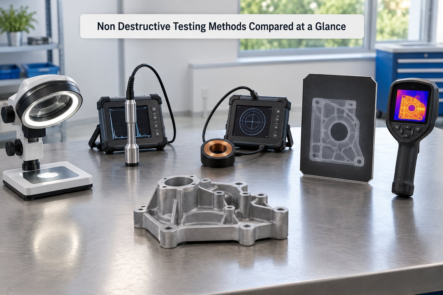
| Method | Best for | Detects | Material limits | Access needed | Relative cost and speed |
|---|---|---|---|---|---|
| Visual testing (VT) | First-line screening and surface condition checks | Surface cracks, corrosion, discoloration, deformation, porosity, contamination | Any material, no physical limit at all | Line of sight, or a borescope for hidden areas | Cheapest and fastest of the five |
| Ultrasonic testing (UT) | Internal flaws and thickness measurements | Internal cracks, voids, delamination, inclusions, wall thinning | Works on most solids; coarse-grain materials scatter sound | Contact probe access plus a couplant | Moderate cost, slow but quantitative |
| Eddy current testing (ET) | Fast surface and near-surface scanning on conductive parts | Surface and shallow cracks, corrosion thinning, conductive coating thickness, heat treatment verification | Conductive metals only; no coating over the area of interest | Probe contact on a smooth surface | Low to moderate cost, very fast |
| Radiography (RT) | Volumetric internal defects in welds and castings | Voids, inclusions, lack of fusion, slag, density changes, assembly problems | Practical on dense materials; heavy or thick parts get harder | Both sides of the part, plus a controlled area around it | Highest cost, moderate speed, permanent film or digital image |
| Thermography (TT) | Large-area screening and subsurface disbonds | Delamination, voids, water retention, insulation voids, corrosion under insulation, blockages | Surface must respond predictably to heat; emissivity matters | Line of sight from a distance | Moderate cost, very fast over large areas |
Read across a row and you can see why methods get substituted for one another so often. Thermography finds disbonds quickly but only where heat moves predictably; radiography sees the disbond anywhere in the material but takes far longer. That trade-off between coverage and clarity runs through every comparison below.
Visual Inspection: The Fastest First-Line Check
Visual inspection finds what is on the surface: cracks, corrosion, deformation, discoloration, porosity, and contamination that would ruin a finished part. It costs almost nothing and needs no consumables.
What it really needs is an inspector who knows what the part should look like when it is good, good lighting, and a clear line of sight. Those three things are harder to arrange than most people expect.
Why lighting and access decide whether visual inspection works
A hairline crack in a rough casting can hide under ordinary shop lighting and appear instantly under angled light. A borescope or a mirror turns visual inspection into an internal inspection for bores, tubes, and assembled hardware that a straight line of sight cannot reach.
On an injection-molded plastic part, visual inspection also covers flash, sink marks, weld lines, short shots, and ejector pin marks, which are usually easier to grade against a light table than to measure. If you are setting a standard for those, our guide to hardness testing for plastics explained covers the other side of the same material decision.
Where visual inspection falls short
Anything buried inside the part is out of reach. A method that only sees surfaces tells you nothing about a void behind a weld bead or a delamination under a coating, and by the time internal damage shows up as a leak or a crack, the part has already failed in service.
Ultrasonic Testing: Detecting Internal Flaws
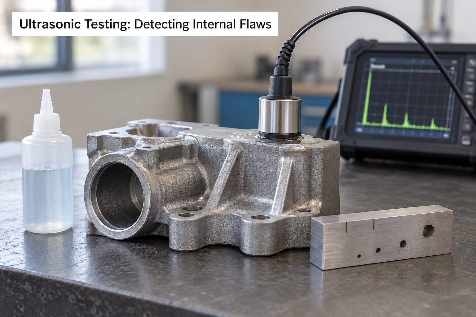
Ultrasonic testing sends high-frequency sound waves through a part and listens to what comes back. A flaw reflects or scatters the sound, and that change in the signal is the indication. It is the most sensitive method for internal flaws and the only one of the five that also measures thickness directly.
How pulse-echo and through-transmission differ
In pulse-echo, one probe sends and receives, and the time between the transmitted pulse and the echo tells you how deep the reflector sits. In through-transmission, separate emitters and receivers sit on opposite sides, which gives a simpler readout but needs access to both faces.
Phased array ultrasonic testing fires many elements at controlled angles from one probe, which sweeps a wedge of material and builds an image. It finds more per second than conventional UT and works through thicker sections, but the equipment and the data interpretation are a step up in complexity.
What couplant and geometry do to the result
The probe needs a couplant to carry sound out of the part. Without it you get no signal, with too much you lose sensitivity, and on rough or curved surfaces the couplant layer can hide small near-surface defects.
Sound also attenuates. Very high frequencies find tiny flaws but fade quickly, so inspecting a thick casting means accepting coarser resolution, and the first few millimetres under the probe surface sit in a blind zone where near-surface cracks hide.
Coarse-grain materials like austenitic stainless and many castings scatter sound badly. On those, angled beam techniques such as time-of-flight diffraction recover much of the lost sensitivity, and where that is still not enough, radiography or a computed tomography scan is the usual next step.
Eddy Current Testing: Fast Surface and Near-Surface Inspection
Eddy current testing passes an alternating current through a coil held near a conductive metal, and that current induces circulating eddy currents in the part. A crack interrupts those currents, and the probe picks up the change as a signal.
No couplant, no radiation, no disassembly. Once the setup is calibrated, an array of probes can scan a heat exchanger tube sheet or a fastener hole faster than almost anything else in this list.
Skin depth, lift-off, and what the phase means
The current sits in a layer near the surface called the skin depth, which grows with lower frequency and with lower electrical conductivity. That depth sets the ceiling on what eddy current can see, so deep corrosion thinning needs a different probe frequency than a fine surface crack.
Lift-off is the gap between probe and surface. Hold the probe a fraction of a millimetre high and the signal weakens sharply, which makes the method difficult on rough, curved, or uneven surfaces. In conductive coating inspection, that same sensitivity becomes the measurement, since coating thickness changes the lift-off on purpose.
The phase of the crack signal rotates with depth. An inspector reads that rotation to estimate how far below the surface the crack runs, which is how one pass gives both location and approximate size.
Material and geometry limits
Eddy currents only exist in electrical conductors, so austenitic stainless, aluminium, copper, and nickel alloys all work while plastics, glass, and concrete do not. Rough forgings and as-cast surfaces also fight the technique because the probe cannot sit flat.
For the matching material-selection discussion on fluoropolymers, see PTFE vs PFA vs FEP compared, where material choice changes which inspection methods stay open to you.
Radiography: Seeing Dense or Hidden Defects
Radiography passes ionizing radiation through a part and captures how the density varies on the far side. Where metal is thicker, or where a void of slag or gas interrupts it, the film or digital detector records a difference. It is the only one of these five methods that shows you the internal condition as an image.
What radiography catches that other methods miss
Voids, inclusions, porosity, lack of fusion in welds, and misplaced fasteners all show up in an image in their actual positions. That makes radiography the standard for volumetric weld inspection on code work, where a code-compliant image is itself the deliverable.
Orientation is the limit worth remembering
A planar crack perpendicular to the beam shows a strong, sharp line. Tilt that same crack even slightly and the image weakens fast, which is why radiography and ultrasonic testing are so often paired on critical welds, each covering the other’s blind spot. Thick or highly attenuating parts need higher energy sources and longer exposure, and heavily irradiated materials can become embrittled.
Radiation safety and access control the schedule
Only ionizing radiation among these methods, so radiography runs under a controlled area with dosimetry, a survey meter, and a qualified radiation safety officer. Both sides of the part need access, and the work often happens outside the factory after hours so the production line keeps running.
Thermography: Non-Contact Inspection of Heat Patterns
Thermography measures infrared radiation and turns surface temperature into a picture. In passive inspection, you simply look for a thermal pattern that does not belong. In active inspection, you apply heat externally or internally and watch how it moves through the part.
Active and passive thermography solve different problems
Flash thermography, the most common active form, floods the surface with a short pulse of light or heat and records how quickly each area cools. A delamination or void blocks heat flow, so it cools slowly and shows up as a warm patch minutes later.
Passive thermography finds things that heat themselves: steam or hot-water leaks, failing electrical connections, corroding or blocked equipment, and refractory or building envelope defects. On corrosion under insulation, it is often the only practical first step, though a follow-up method is usually needed to size what it finds.
Why surface condition decides the outcome
Emissivity changes how a surface emits radiation, so bare metal, painted steel, and weathered concrete need different setup and reference readings. Thermal mass matters too: a part that conducts heat slowly can hide a flaw that a fast-conducting one shows immediately. Reflections from shiny or low-emissivity surfaces add noise, and the camera needs a clear line of sight across the whole area it is scanning.
Where thermography fits
It is the natural screening tool for composites, bonded assemblies, insulation, large castings, and anything you cannot touch. When the thermal pattern says something is wrong, you still need a second method to confirm depth and size.
How to Choose the Right Non Destructive Testing Method
Start with the defect, not the equipment. Work through these questions in order and the method usually picks itself.
1. Where is the flaw?
Surface-breaking flaws are the cheapest to find. Liquid penetrant and magnetic particle testing have no equipment counterpart in this guide, but among these five, visual inspection handles a clear surface defect, eddy current handles a fine one on conductive material, and thermography handles large areas rather than single cracks.
2. Is it subsurface or buried?
Internal voids, delamination, and lack of fusion need either ultrasonic testing or radiography. Choose ultrasound for thin-walled parts, tight geometry, and when you want thickness as well as flaw location. Choose radiography for castings, heavy sections, and code work where a permanent image is required.
3. What is the material?
Eddy current needs electrical conductivity. Radiography and ultrasonic testing are far more forgiving with material type. Thermography needs a surface that responds predictably to heat. Plastic components usually combine visual inspection with ultrasonic testing, and our root cause analysis methods for manufacturing defects guide shows why the failure mode decides the method.
4. What does the environment allow?
Radiography needs a controlled area and cleared access on both sides. Eddy current needs smooth metal under the probe. Ultrasonic testing needs a coupling surface and time to scan slowly. Thermography needs a line of sight and, for active work, controlled ambient temperature.
5. What speed and record does the job need?
Visual and thermography deliver results in seconds. Eddy current scans a whole tube sheet in a shift. Ultrasonic and radiographic inspections are the slow pair. On a line that runs at speed, screening with visual, thermography, or eddy current and confirming with ultrasound is the common split. When traceability matters, radiographic images and stored ultrasonic data become part of the record; visual inspection usually does not.
6. Relative cost, without the invoices
Visual inspection costs almost nothing beyond training. Thermography and eddy current sit low to moderate, mostly in equipment and setup time. Ultrasonic testing costs more per hour but scales down with automation and phased array. Radiography carries the highest overhead because of shielding, dosimetry, staffing, and controlled-area scheduling. Consumables push liquid penetrant testing up too, since it needs cleaning and preparation time on every part.
Which Should You Choose?
Match the method to the job, then adjust for your access and documentation needs.
Incoming inspection of purchased material
Visual inspection on receipt, with sampled ultrasonic testing for bars, plate, and tube where internal quality is a known supplier problem. Radiography earns its place on critical or coded components only.
Weld inspection
Visual inspection first, always, then radiographic testing on pressure and structural welds for volumetric conditions. Add ultrasonic testing where access allows and cracking is the worry. In oil and gas pipeline work, both radiography and ultrasonic testing are routine, and the code decides which combination applies.
Aerospace and composites
Eddy current and ultrasonic testing dominate. Aerospace leans on eddy current for conductive surfaces and fine cracks, and on ultrasonic testing for delamination and disbonds in composites, with phased array increasingly doing the scanning.
Automotive and high-volume production
Eddy current probes on lines that already handle conductive parts, thermography for in-process checks on molded and bonded assemblies, and ultrasonic or radiographic sampling on the first article rather than on every unit.
Plastics and molded parts
Visual inspection handles flash, sink marks, and weld lines. Ultrasonic testing works well on thermoplastics with an immersion or contact probe and a couplant designed for the polymer, while radiography and eddy current are largely unavailable.
Field and in-service work
Thermography for screening, visual inspection with drones or borescopes for inaccessible structure, and radiography or ultrasonic testing for confirming what the screen found. When a method cannot safely reach the part, that fact decides it, not the theory.
When one method is not enough
Combinations are normal practice rather than a sign of indecision. Visual plus ultrasonic covers the welds in one pass. Visual plus penetrant screening plus radiography covers castings where surface and internal conditions both matter. Eddy current plus ultrasonic is the standard pairing for heat exchanger tubing, with thermography first for corrosion under insulation. The pairing exists because each method has a blind spot the other fills, and crews who carry two methods report faster and fewer repeat visits.
Frequently Asked Questions
Which non destructive testing method is best for internal defects?
For internal flaws, ultrasonic testing and radiography are the two methods built for the job. Ultrasonic testing works best on thin sections, tight geometry, and anywhere you also need a thickness reading. Radiography works best on castings, heavy sections, and coded welds where a permanent image is required. On critical welds, crews often run both because a crack orientation that hides from one method shows up in the other.
Does non destructive testing damage the part?
Non-destructive testing is defined by the fact that the part stays fit for service afterwards. Surface cleaning for penetrant or magnetic particle inspection removes a thin layer of material, and high-energy radiography can affect some alloys, but the techniques themselves do not cut, load, or consume the component. That is exactly why parts get inspected instead of sectioned when a scrap value is high or a component cannot be replaced.
What NDT method works best on plastic parts?
Visual inspection covers most plastic part defects, including flash, sink marks, short shots, and visible weld lines. Ultrasonic testing is the main tool for anything buried inside the part, such as voids and delamination in molded or bonded components, using an immersion tank or a contact probe with a couplant compatible with the polymer. Radiography and eddy current are generally unavailable, since plastics neither absorb radiation meaningfully nor conduct electricity.
Which NDT test is best in general?
There is no single best method, because each one covers a different depth and a different material class. Visual inspection is the right first step almost every time. Ultrasonic testing gives the most sensitive internal inspection on most solids. Eddy current testing is the fastest option for conductive parts with fine surface cracks. Radiography produces the only true internal image, and thermography covers large surfaces without contact.
When is one NDT method enough?
One method is enough when the part has a single known failure mode and a material that suits it. A polymer part with visible cosmetic and flash defects needs visual inspection alone. A coded pipeline weld needs radiography because the code requires a documented image. Real complexity arrives when a part can fail internally and at the surface at once, or when the material rules out the obvious technique, and that is when a second method becomes the sensible call.
How do inspectors verify NDT results?
Results are verified by calibration, reference standards, and qualified personnel. Instruments are checked against calibration blocks or reference pieces before and after use, and the operator holds a qualification such as SNT-TC-1A Level II for the method and industry. Repeat inspections with a different method confirm borderline indications, and every accepted or rejected call is recorded so the decision can be audited later.
What to Do First
Write down the failure mode you are actually worried about, not the inspection method you have in mind. Surface-breaking and clear of material rules, visual inspection plus one of the specialised techniques settles it. Internal flaws in most solids point to ultrasonic testing, with radiography for heavy sections and coded weld documentation.
Then check the material and the access before committing. Eddy current needs conductivity and a clean surface, thermography needs a line of sight and predictable thermal behaviour, and radiography needs both sides of the part and a controlled area. Once you know the depth you need to see and what the part allows, the method is usually obvious, and pairing a fast screen with a confirming technique keeps inspection time and repeat visits down.