
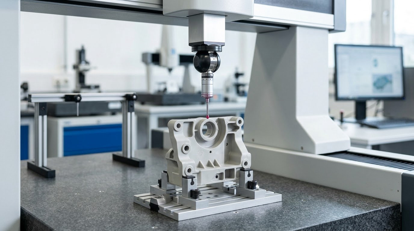
A coordinate measuring machine (CMM) is a precision metrology instrument that works by touching a part with a probe, recording the X, Y and Z position of thousands of points, and comparing that point cloud against the CAD model or drawing to report actual sizes and geometric tolerances. CMM inspection basics for plastic parts matter because a molded component is rarely the shape the toolmaker intended: shrinkage, moisture, and warpage all move the part after the cavity closes.
Here is the part most shops get wrong. A CMM will happily produce a clean, traceable, fully documented report about a part that was measured warm from the press, still damp, or clamped hard enough to push a thin wall out of shape. The machine is not the weak link in that case. The setup is.
Below is what a CMM actually measures, how the measurement sequence runs, what plastics add to the difficulty, and when a caliper or a plug gauge is the smarter tool.
Table of Contents
- What Is CMM Inspection for Plastic Parts?
- What Does a CMM Measure on a Plastic Part?
- How Does a CMM Inspection Work?
- Manual, CNC, and Optical CMMs: Which One Fits?
- How to Prepare Plastic Parts for CMM Inspection
- How to Choose Datums and Inspection Features
- What Is the Step-by-Step CMM Inspection Process?
- How Do You Read CMM Results and Tolerance Reports?
- Why CMM Results Can Differ for Plastic Parts
- How to Troubleshoot Common CMM Inspection Problems
- How Accurate Does CMM Inspection Need to Be?
- Where CMM Inspection Fits in Plastic Part Quality Control
- Frequently Asked Questions
- Can a CMM inspect plastic parts?
- Which plastic part features are best measured with a CMM?
- What is the difference between resolution and accuracy on a CMM?
- Should plastic parts be measured as received or after conditioning?
- What is a good rule of thumb for choosing CMM datums?
- When is a CMM unnecessary for inspecting a plastic part?
- Conclusion
What Is CMM Inspection for Plastic Parts?
CMM inspection is dimensional and geometric verification of a finished part against a drawing or CAD model, performed on a machine that moves a probe in three axes and reports where the probe actually touched the part. On a molded component it replaces guesswork with numbers: hole position relative to the bosses, seal land profile, draft, warpage, and every linear dimension on the ballooned drawing.
Visual inspection catches what you can see. A scratched cosmetic face, a short shot, a flow line, a flash at the parting line. It catches nothing about true position, and it cannot tell you whether a 2.5 mm bore is 2.48 or 2.53.
Hand gauges catch some of that. Calipers, micrometers, and plug gauges give a number, fast, and for a single simple feature they are often the better choice. What they cannot do is establish a coordinate system from three datum features and then measure 40 other features relative to it without resetting the part each time. That is the gap the CMM fills.
What Does a CMM Measure on a Plastic Part?
The CMM measures a point cloud, then fits geometry to those points. A circle fit through 24 probed points gives a diameter, roundness, and size error. A series of points across a face gives flatness. The software does the math; the value of the result depends entirely on which points were probed and how the part was held.
| Feature | What the CMM reports | Why it matters on a molded part |
|---|---|---|
| Overall length, width, height | Actual size plus deviation from nominal | Catches shrink variation between cavities and across a production lot |
| Hole diameter and depth | Diameter, size error, bore profile, taper | Shrinkage hits bores differently than outer walls; draft shows up as taper |
| Hole position and true position | Position of the axis relative to the DRF | Determines whether a fastener or a press fit actually lands |
| Wall thickness | Thickness at defined sections | Thin walls move with moisture and clamp load |
| Seal land or sealing groove profile | Profile of a surface deviation | Leak paths live here; a line profile callout needs a CMM |
| Flatness and warpage | Total deviation from a plane | Out-of-flat is common on large molded panels and housings |
| Perpendicularity, parallelism | Orientation of a feature to a datum plane | Stops a cover from seating flush |
| Draft angle | Angle of a wall relative to the draw direction | Zero draft on a textured surface means the part will not eject cleanly |
| Boss and hole concentricity | Axis-to-axis relationship | Off-center bosses become wobble in assembly |
| Keyway and slot width | Width, position, side-to-side symmetry | Slotted features are a classic source of gate vestige in the point cloud |
How Does a CMM Inspection Work?
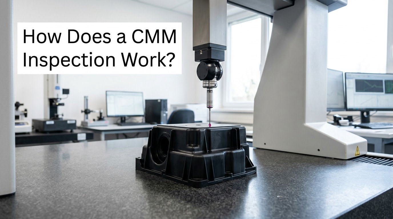
Every CMM run, manual or CNC, follows the same five steps. The differences between machines are in how the steps get executed, not in what they mean.
- Import the nominal data. The CAD model or drawing tolerances load into the CMM software, either as a CAD comparison or as a ballooned drawing with feature callouts and tolerances attached.
- Align the datum reference frame. The operator probes the datum features, the software fits a coordinate system to them, and every subsequent number is reported in that system.
- Probe or scan the features. A touch-trigger probe records discrete points on contact. A scanning head sweeps hundreds or thousands of points per second, which is far faster but applies light continuous contact force.
- Fit and compare. Algorithms fit cylinders, planes, and point clouds to the data, then evaluate them against the drawing: size, form, orientation, location, and runout.
- Report. You get pass or fail, actual values, deviations, and a record of the datum scheme, fixture, temperature, and operator used. That record is the actual product of the inspection.
One detail that trips up newcomers: probing picks up whatever the probe touches. A gate vestige, ejector pin mark, or parting flash sitting inside a scanned region becomes part of the point cloud, and the fit algorithm will happily treat it as material. Features near the gate often need masking in the program.
Manual, CNC, and Optical CMMs: Which One Fits?
These are three different ways of answering the same question, and the right one depends on part size, feature access, and how many parts you measure a week.
| Approach | Best use on plastic parts | Limitation |
|---|---|---|
| Manual bridge CMM | Low-volume parts, short features, first articles, quick verification | Operator-dependent; a single probe move can introduce a cosine error |
| CNC bridge or gantry CMM | Repeat production inspection, programs that run unattended, dozens of features per part | Programming and fixture setup take longer up front |
| Portable articulating arm | Large housings, tooling, and parts too big for a bridge; measurement on the press floor | Lower accuracy, sensitive to operator technique and vibration |
| Optical and laser scanning CMM | High-point-density work, complex surfaces, texture and freeform geometry, soft or polished parts | Chromatic sensors are sensitive to surface finish and ambient light; calibration is finicky |
For thin-wall molded parts, non-contact measurement is often the safer answer, because nothing touches the part. The trade is accuracy: an optical system needs a good matte surface to work on, and a glossy injection-molded texture is a poor reflection target.
How to Prepare Plastic Parts for CMM Inspection
Preparation decides whether the number is real. Work through these in order, and change nothing about the part that you are about to measure.
- Clean it. Dust, release agent, and handling grease shift contact points. Use a lint-free wipe and a cleaner that will not attack the resin, and never handle a datum face with bare fingers if skin oil matters to the fit.
- Let it reach temperature. A part pulled off the press is far above room temperature. Standard practice is 20 °C plus or minus 0.5 °C, the same window a calibration lab is held to, and a part measured hot will read large on every dimension. Let thick sections stabilize; they give up heat far more slowly than a thin wall.
- Settle the moisture state. Polyamides and many other resins absorb moisture from the air and swell measurably. Decide and record whether parts are measured dry-as-molded or conditioned to equilibrium, because the two states differ by more than most tolerances you would specify on a drawing.
- Remove flash and vestige carefully. Deburr, but do not sand a feature flat to get a reading to pass. A dressing tool that removes material is a process change, not a measurement fix.
- Mark identification without touching critical surfaces. A part number, cavity number, and lot number on a non-critical face or on a tag keeps the report traceable to one cavity, which matters more than most people expect.
- Do not clean up cosmetic defects before inspection. If a sink mark is under the scan path, mask it in the program or accept that the form result includes it.
How to Choose Datums and Inspection Features
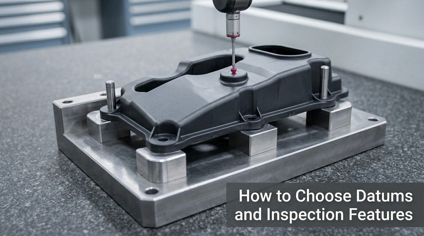
A datum is a feature you use to hold the part in a known position and orientation. Three properly chosen datum features establish a datum reference frame, and every measurement after that is reported relative to that frame. Choose them from how the part actually functions, not from whatever surface is easiest to probe.
A good primary datum is a broad, stable surface the part genuinely sits on in service. A secondary and tertiary datum should locate rotation and then position, and they should be features that mating hardware or the assembly fixture already references. If you pick a cosmetic rib as a datum because it is easy to touch, you have built an alignment that has nothing to do with the part’s job. The background on how datum features are called out lives in our GD and T basics for plastic parts guide.
Molded parts complicate this. A housing with no flat mounting face may have no true locking datum at all, and the inspector falls back on a best-fit routine that finds the actual axes of the features. That is a legitimate approach, but it should be written into the inspection plan, because best-fit alignment and datum alignment produce different numbers and either one can be defended only if the customer agreed to it in advance.
For features, the rule is simple: probe every characteristic the drawing controls, and skip the ones the process holds tightly. Nobody needs CMM data on a cosmetic texture, and everybody needs it on true position, profile, and total runout.
What Is the Step-by-Step CMM Inspection Process?
Here is the workflow a good inspection actually follows, from the drawing to the signed report.
- Review the drawing before anything else. Confirm revision, tolerance scheme, material condition modifiers, and which characteristics are critical. Most inspection disputes turn out to be drawing disagreements found too late.
- Set up the program. Load the CAD comparison or the ballooned report, define the datum scheme, and choose the features to measure. Write the program once and reuse it; rewriting per part is how inconsistencies creep in.
- Align the part. Seat it in the fixture, confirm no debris under the locating surfaces, and probe the datums. On a warped molded part, check the seating with a feeler before you accept the alignment.
- Qualify the probe. Run the stylus qualification and check the reference sphere so the system knows the effective stylus length and ball diameter. Probe force matters more on plastic than on metal: a heavy touch on a thin wall pushes the surface and inflates the reading.
- Measure the features. Work through the program, keeping the probe path away from gate vestige and flash unless the drawing controls that region.
- Validate the run. Re-probe a datum and confirm the fit residuals are sensible. A CMM that reports a perfect result from a bad alignment is worse than no result at all.
- Review and release the report. Check header fields: part number, revision, cavity, instrument ID, calibration date, temperature, conditioning state, and datum scheme. Then decide pass or fail against the drawing, not against the average.
How Do You Read CMM Results and Tolerance Reports?
Every result is a comparison between a nominal and an actual. Read the deviation, not the actual alone, because a part can measure 25.02 mm and still be out of tolerance if nominal is 25.00 with limits of 24.98 to 25.02 plus a 0.05 form allowance that the fit already consumed.
Form, orientation, location, and profile each report differently. Size characteristics such as hole diameter use a two-point or least-squares zone. Flatness reports total deviation from a best-fit plane, so a part can be within flatness and still not lie flat on a table. Profile of a surface is a single number describing the whole band of deviation, and it is the callout that most often condemns a seal land.
When a feature of size carries a material condition modifier, the tolerance zone grows at maximum material condition. A hole at MMC has bonus tolerance equal to the difference between its actual size and its MMC size, and the report should show the bonus explicitly. If it does not, ask.
Worked example, typical numbers on a molded housing. Hole diameter nominal 6.00 mm, limits 5.97 to 6.03, measured 6.010, so it passes on size. True position is a 0.15 mm diameter zone at MMC, measured 0.128. Because the hole is 0.010 above its MMC size of 6.00, the bonus is 0.010, the allowed zone is 0.160, and the part passes. Had the hole measured 5.985, the zone would have been 0.135 and the same 0.128 true position would have failed. Size and location cannot be read separately on a report like that.
One more habit: flag near-boundary results. A true position of 0.148 in a 0.150 zone passes today, but it tells you the process is drifting, not that the part is good. Our plastic part tolerance standards guide covers where the achievable limits sit for molded parts.
Why CMM Results Can Differ for Plastic Parts
Two labs can measure the same part and disagree, and on molded components the material is usually the reason. The part keeps moving after it leaves the mold.
The tricky part of CMM inspection basics for plastic parts
Shrinkage is the big one. It is not a defect, it is physics: the polymer cools and contracts, and the part comes out smaller than the cavity that made it. Nominal on the drawing should reflect the finished part, not the steel, and a drawing quoted to cavity dimensions guarantees a floor full of “failures” that are really correct parts measured against the wrong number.
| Resin | Typical shrinkage | Measurement implication |
|---|---|---|
| ABS | 0.4 to 0.9 % | Tight and stable; modest growth with conditioning |
| Polycarbonate | 0.5 to 0.7 % | Very consistent, but high thermal expansion when warm |
| Polypropylene | 1.0 to 2.5 % | Wide range; flow direction matters more than nominal alone |
| 30 % glass-filled polypropylene | 0.2 to 0.7 % | Near-dimensionally stable, but anisotropic and very dependent on fiber orientation |
| HDPE | 1.5 to 3.0 % | High and irregular; flow-marked areas and sink marks need masking |
| PA6 | 1.0 to 2.0 % | Hygroscopic; shrinks as it dries, grows as it absorbs |
| PA66 | 1.0 to 2.0 % dry-as-molded, 0.5 to 1.5 % conditioned | The conditioning state can move a dimension by more than a typical tolerance |
Beyond material, the variables that move a result are mostly about the setup. A part clamped hard in a fixture gets a different answer than the same part resting free, and a free-state measurement and a restrained measurement of the same warped panel will not agree. Decide which one the drawing means. Probing force and scanning force distort thin walls, and a scanning head sweeping a flexible wall applies force continuously rather than once at contact.
Then there is the environment and the uncertainty budget. A granite table and a part are both at 20 °C plus or minus 0.5 °C, and plastics move with temperature far more than steel does. Finally, measurement uncertainty: a result reported to three decimals carries a real error band, and two labs with different equipment can both be right and still print different numbers.
How to Troubleshoot Common CMM Inspection Problems
| Symptom | Likely cause | Fix |
|---|---|---|
| Same part, different numbers run to run | Part not seating consistently, or warped parts clamping differently | Add positive location, check for debris, and reduce clamp force on thin sections |
| Every part shows a datum shift | Datum features are loose or not actually controlling orientation | Pick datums that the assembly actually uses and constrain the part in more than one place |
| Diameter reads large on soft features | Probe or scan force pushing into the material | Use a lighter stylus force or a non-contact head, and re-qualify the probe |
| Form results unexpectedly poor | Gate vestige, ejector marks, or flash inside the sampled region | Mask the non-controlled areas in the program or move the sample points |
| Results that do not match the caliper reading | Different conditioning state, temperature, or datum scheme | Check the report header against the conditions of the caliper check |
| Report missing information | Template or program not configured for traceability fields | Fix the output template once; never accept a report without instrument ID and cavity number |
| One cavity consistently out | Cavity-to-cavity variation, not a measurement problem | Compare per-cavity means before touching the inspection method |
On multi-cavity tools, this last one matters. Inspectors often pool parts from every cavity into one data set, which averages a good cavity against a bad one and reports a process that is fine on paper. Sample each cavity separately, at least five parts per cavity, and compare the means.
How Accurate Does CMM Inspection Need to Be?
Accuracy is often over-specified. A machine’s maximum permissible error, MPE_E, is defined under ISO 10360 as E = 1.7 + L/300 micrometres, where L is the measured length in millimetres, and a real quality lab publishes a much tighter figure for a specific size range. You do not need the tightest machine on the market. You need the machine whose error is a small fraction of your tightest tolerance.
The standard rule of thumb is a resolution-to-tolerance ratio of at least 10 to 1, and 4 to 1 where a customer agrees in writing. A 0.01 mm tolerance wants at least 0.001 mm resolution, which rules out a machinist rule and most digital calipers. A loose 0.5 mm general tolerance on a non-critical wall thickness needs nothing more than a good caliper, and asking for a CMM there wastes hours and money.
Resolution and accuracy are different things. Resolution is the smallest increment the instrument displays. Accuracy is how close the reading is to truth. An instrument can display 0.0001 mm and still be off by 0.005 mm if it is warm, out of calibration, or compensating poorly for stylus length. Ask for the calibration certificate, check the date, and confirm the certificate states MPE_E for the volume your part occupies.
Feature size sets the floor too. Measuring the position of a 0.4 mm hole to 0.01 mm is a claim about a feature smaller than the probe can reliably center. When the tolerance approaches the feature, the result is dominated by probe geometry rather than by the part.
Where CMM Inspection Fits in Plastic Part Quality Control
CMM inspection is one tool in a quality system, and using it at the wrong stage is pure cost. This is roughly where it earns its place.
- Supplier qualification and audit. A CMM report on one part per critical supplier tells you whether their measurement system and their process are both under control.
- First article inspection. Required for PPAP submission and for regulated work such as medical or aerospace components. Run the full ballooned drawing, and treat the report as a baseline for later comparison.
- Process capability studies. Measuring 25 to 30 consecutive parts gives real Cp and Cpk numbers instead of an opinion about whether the process is capable.
- In-process checks. A portable arm near the press catches drift before it becomes a lot of scrap, provided the parts have stabilized first.
- Failure and nonconformance analysis. When a molded part did not fit, the CMM report tells you whether the feature was out or the assembly was. That distinction saves a lot of argument. If the method itself is in doubt, verify the method before conceding a part, and document any concession.
- Not every stage. Incoming screening of general tolerances, cosmetic disposition, and in-cavity flash checks are faster and cheaper with gauges, a vision system, and the eyes of a trained operator. The full sequence for release documentation is covered in how to run a first article inspection.
Before any of that, confirm the measurement system itself. A gauge repeatability and reproducibility study on a molded part tells you whether the variation you are chasing belongs to the part or to the inspection. Without that, a capability number is a guess with decimals.
Frequently Asked Questions
Can a CMM inspect plastic parts?
Yes, and it is one of the best tools for the job, but only if the part is measured in a defined state. Temperature, conditioning, fixture clamping, and probe force all change the result on a molded component. A rigid molded housing measures beautifully. A warped thin-wall panel measured free-state or restrained gives two different answers, and neither is wrong until you say which one the drawing meant.
Which plastic part features are best measured with a CMM?
Anything that depends on a coordinate system rather than a single reading: true position, hole pattern location, seal land profile, flatness, perpendicularity, runout, and draft. Those cannot be evaluated correctly by picking the part up and measuring features one at a time. A simple wall thickness or overall length is well served by a caliper or micrometer, and using a CMM for it is wasted time.
What is the difference between resolution and accuracy on a CMM?
Resolution is the smallest step the machine can display, and accuracy is how close its readings are to the true value. A machine can display readings to 0.0001 mm and still be off by 0.005 mm if it is warm, poorly calibrated, or has the wrong stylus compensation. Check the calibration certificate for MPE_E, and treat resolution as a display property rather than evidence of accuracy.
Should plastic parts be measured as received or after conditioning?
Whatever the drawing and the customer agreement say, written down before the first part is measured. For hygroscopic resins such as PA6 and PA66, the difference between dry-as-molded and conditioned can exceed the tolerance you are trying to hold. Record the conditioning state, temperature, and time since molding on the report so the number can be defended later.
What is a good rule of thumb for choosing CMM datums?
Choose the datums the part actually functions on, not the surfaces that are easiest to probe. A broad, stable face the component seats on makes a good primary datum; a locating feature and a screw hole normally complete the frame. Three properly chosen features let the software establish a stable reference frame, and every measured value is then reported consistently relative to it.
When is a CMM unnecessary for inspecting a plastic part?
When the characteristics are simple, loosely toleranced, and already controlled. Overall dimensions, general wall thickness, cosmetic defects, flash, and thread go-no-go checks are faster with calipers, depth gauges, plug gauges, and visual inspection. Reserve the CMM for true position, profile, form, and orientation, and for the release evidence your customer actually requires.
Conclusion
CMM inspection basics for plastic parts come down to preparation, not machinery. The machine gives you numbers; the cleaning, the temperature, the conditioning state, the datum scheme, and the fixture decide whether those numbers mean anything.
Start by confirming the drawing revision, the inspection state you will measure in, the datums, the critical features, and the acceptance tolerances. Agree all five with the customer before the first part is measured, and every report after that becomes evidence rather than argument.