
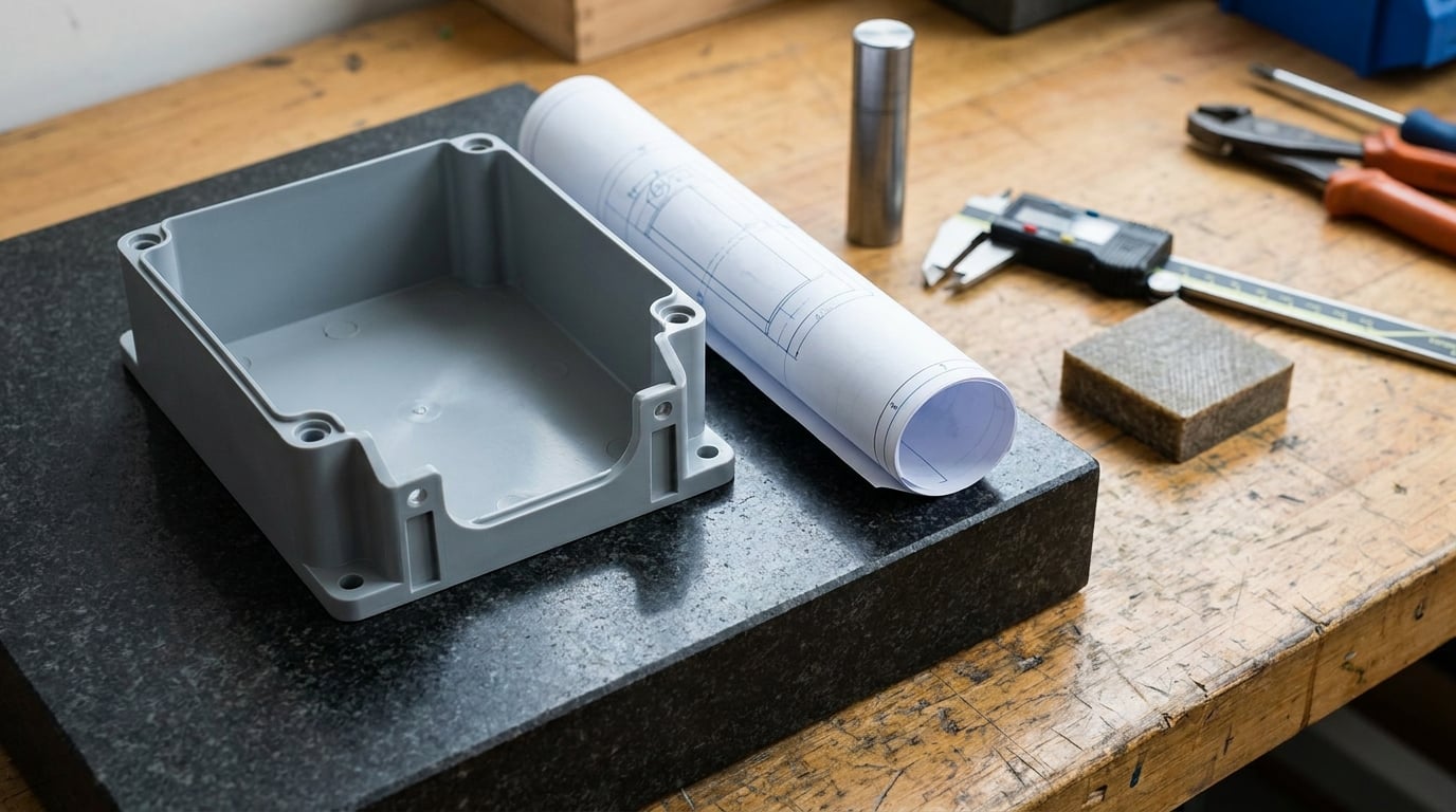
GD&T basics for plastic parts come down to one idea: instead of writing where a feature should be, you write what shape, position, and orientation it must keep relative to the surfaces the part actually assembles against. Polymers shrink, warp, creep, and expand far more than metal, so a plain plus/minus dimension hides variation that matters in the assembly. The framework is written down in ASME Y14.5 and the ISO GPS standards, with ISO 2768 covering general tolerances.
Most plastic parts that fail on the line do not fail because a dimension was out by 0.05 mm. They fail because two holes drifted apart relative to a mating boss, a cover bowed just enough to open a gap, or a snap-fit arm sat outside its travel because nobody defined the datum scheme. GD&T is the notation that stops those failures from being arguments.
Below is the working version: what the symbols mean, where datums come from, how material condition modifiers change the numbers, and how to set tolerances a plastic process can actually hold.
Table of Contents
- GD&T Basics for Plastic Parts: What the Framework Covers
- What Does GD&T Stand For?
- Which GD&T Symbols Are Most Common on Plastic Part Drawings?
- How Do Datums and Datum Features Work?
- How Do You Choose a Datum Reference Frame for a Plastic Part?
- What Are Material Condition and Modifiers?
- How Do Position Tolerances Control Plastic Holes and Features?
- What GD&T Symbols Are Best for Warpage, Draft, and Molded Surfaces?
- How Do You Set Feasible Tolerances for Injection-Molded Plastic Parts?
- How Does GD&T Change Inspection and Measurement?
- What Does a Practical GD&T Drawing Example Look Like?
- What Are Common GD&T Mistakes on Plastic Parts?
- Using an ambiguous datum that nobody can simulate
- Specifying inspection access that does not exist
- Tolerancing more features than the function needs
- Confusing position with size
- Ignoring moulding variation the tolerance cannot control
- Adding RFS or MMC modifiers by habit
- Controlling flatness on a surface that was never flat
- Specifying the resin too loosely
- Frequently Asked Questions
- Is coordinate dimensioning acceptable for plastic parts?
- What is the difference between a datum feature and a datum?
- Does using a CMM automatically make a part GDu0026amp;T compliant?
- How should cosmetic warpage be controlled on a molded plastic cover?
- Should plastic part tolerances include extra allowance for shrinkage and molding variation?
- Conclusion
GD&T Basics for Plastic Parts: What the Framework Covers
Geometric dimensioning and tolerancing is a symbolic language for describing allowable variation in shape, orientation, position, and runout. Ordinary dimensions answer “how big.” GD&T answers “how correct, relative to what.” On polymer parts that distinction decides whether a part is inspectable at all.
A molded cover might be dimensioned 120 plus or minus 0.3 everywhere and still be useless, because nothing in that callout ties the sealing face to the screw bosses. Add a flatness callout on the sealing face, reference it to the three mounting bosses, and the drawing states the one thing the assembly actually cares about: how coplanar those features are to each other.
The framework has four moving parts, and every later section in this guide expands one of them.
| Element | What it states | What it leaves out | Typical inspection |
|---|---|---|---|
| Coordinate dimensions | Size and nominal location of each feature | How features relate to one another, and how well the form is controlled | Calipers, micrometers, basic measurements |
| Datums and datum reference frame | The surfaces the part is located from | The allowable variation itself | Setup on a fixture or CMM alignment routine |
| Feature control frames | Symbol, tolerance value, datum references, modifiers | Size, which comes from the dimension callout | CMM, optical comparator, functional gauge |
| Material condition modifiers | How the tolerance changes as the feature size departs from its limit | Anything about the process that produced the size | Calculated from the measured feature size |
| General tolerances (ISO 2768) | Uncontrolled linear and angular dimensions | Anything you explicitly called out | Any suitable method |
Read that table as a division of labour. Dimensions give size. Datums give orientation. Feature control frames give the relationship. ISO 2768 cleans up whatever you did not bother to call out, which is exactly why the decisions you do make matter so much.
What Does GD&T Stand For?
GD&T stands for geometric dimensioning and tolerancing. It replaces long notes about how a feature should be held with a compact frame of symbols that any trained inspector can read the same way you meant it.
Engineers group tolerances into four families, and it helps to know which family a callout belongs to.
- Unilateral tolerance. Variation runs one way only from the nominal size, with no limit on the other side. A shaft specified from 10.000 to 10.030 is unilateral.
- Bilateral tolerance. Variation runs both ways from nominal, like 20 plus or minus 0.2. The most familiar form, and the one that quietly allows equal error in both directions even when the fit only tolerates error one way.
- Limit tolerance. Maximum and minimum values are stated directly as limits, with no nominal in between. Common in inspection practice.
- Geometric tolerance. The GD&T family. Controls form, orientation, location, and runout through a feature control frame rather than through a number on a dimension line.
The difference from coordinate dimensioning is not accuracy, it is intent. Coordinate dimensioning asks whether each feature sits within its own little box, measured from the printed numbers. Two parts can both pass and still have hole patterns that differ from each other by the full sum of the errors, which is how assemblies end up with parts that are individually perfect and collectively wrong.
On a molded part there is a second problem. A draft face is not nominally flat, a rib root is not nominally at the theoretical wall intersection, and a sink-marked surface is not a design surface at all. Plus/minus dimensions on those features generate arguments rather than answers. A geometric callout tied to a proper datum either accepts the variation as intentional or rules it out cleanly.
Which GD&T Symbols Are Most Common on Plastic Part Drawings?
Thirteen symbols cover the overwhelming majority of real plastic part drawings. Here is what each controls and the molded or machined feature it is usually applied to.
| Symbol | Characteristic | What the tolerance zone allows | Typical plastic application |
|---|---|---|---|
| Straightness | Form | Two parallel lines or a cylinder, depending on whether it applies to a surface or an axis | Axial straightness of a machined bore between two bearing journals |
| Flatness | Form | Two parallel planes a set distance apart | A machined mounting pad or a lightly machined cover face |
| Circularity | Form | Two concentric circles, no datum required | Roundness of a molded pin or a turned shaft section |
| Cylindricity | Form | Two coaxial cylinders separated by the tolerance | A bearing bore where roundness and straightness both matter |
| Profile of a surface | Form | A zone between two offset surfaces, with no datum by default | A complex molded or machined contour such as a lens window or seal land |
| Angularity | Orientation | A zone between two planes rotated by the tolerance about a datum axis | Orientation of a drafted side face relative to the parting plane |
| Perpendicularity | Orientation | A zone between two parallel planes, or a cylindrical zone, normal to a datum | A mounting face square to the bore it is drilled from |
| Parallelism | Orientation | A zone between parallel surfaces or a cylindrical zone parallel to a datum | A second mounting boss parallel to the first so a cover screws down flat |
| Position | Location | A cylindrical or square zone centred on the true position | Any hole or boss pattern: mounting holes, insert locations, boss array |
| Concentricity | Location | A cylindrical zone coaxial with a datum axis | A molded-in metal insert relative to a surrounding bore |
| Symmetry | Location | A zone of two parallel planes symmetric about a datum plane | A two-part snap feature centred on a mating rib |
| Total runout | Runout | The whole surface or feature must lie within the zone during one rotation about the datum axis | A molded circular flange face seated against a mating ring |
| Circular runout | Runout | Each circular element individually lies within the zone | Any turned or molded circular face where squareness is not critical |
Two habits separate drawings that work from drawings that generate disputes. First, form controls carry no datum, so flatness and circularity tell you nothing about where the feature sits. Second, position is almost always the right choice for a hole pattern, and a diameter tolerance on the callout is not a location control at all.
How Do Datums and Datum Features Work?
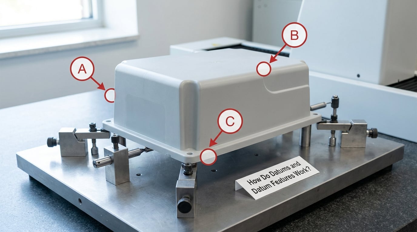
A datum is an imaginary plane, axis, or point that the measurement is taken from. A datum feature is the real surface on the part you are using to create it. Those two are different things, and mixing them up causes more drawing arguments than any other GD&T confusion.
On a plastic part the distinction is easy to feel. Seat the housing in its assembly and it touches the enclosure on three points: a machined rear pad and two cylindrical bosses. Those three surfaces are datum features. The plane and the axis the inspector’s equipment builds from them are the datums.
A datum feature simulator is the physical stand-in for a mating part: a plate, a pin, or a collet that represents the surface the part actually contacts. When a control references datum A, the setup must use a simulator whose contact matches the real assembly. A flat plate on a draft face is not that simulator, and measurements taken that way will disagree with the assembly by more than the tolerance you wrote.
A datum reference frame, or DRF, is the complete set of datums in play: one primary datum that establishes orientation, one secondary, one tertiary, each built from a different feature so the part is fully constrained. The usual sequence is three planar datums, but any combination works as long as it locks every degree of freedom. A single round pin is a good primary datum because rotation about it has to be restrained separately.
One last point worth holding onto: a datum is not automatically a toleranced feature. Sometimes it is. Often it is not, because in the real assembly the part floats or slides against that surface. Reference the boss as datum A, and separately leave its diameter to ISO 2768, unless fit at that boss genuinely matters.
How Do You Choose a Datum Reference Frame for a Plastic Part?
Choose datums from how the part locates in service, not from whichever surface looks flattest on the CAD screen. Work through four questions in order.
1. What does the function require?
Start with the interface that constrains the part. A snap-fit arm needs a datum at the root of the arm, because that is where the load path is. A press-fit boss needs the bore it enters as the primary. A hinged door needs the hinge knuckles as the primary, or the door will never sit square no matter how tight the other tolerances are.
2. Is the feature stable in manufacture?
A primary datum should be large and rigid. On a molded housing, a wide flat pad resists settling better than a small molded pin, and a machined pad beats a raw molded face. A datum that flexes under the measuring force produces readings that move with the fixturing, and no amount of tolerance tightening fixes that.
3. Can an inspector reach it?
This is where plastic parts fail in practice. A datum behind a snap arm, inside a deep draft pocket, or under an overmolded grip may be physically unreachable with a probe or a gauge plate. If the shop cannot simulate the datum, the control is not inspectable, and an uninspectable control is a warranty claim waiting to happen. Move the datum to a machined pad you can actually contact.
4. How much adjustment is left?
The frame should lock as many degrees of freedom as possible, so that a small variation in one direction does not show up as a swing in another. Two planar datums plus one cylindrical, or three planes at non-parallel angles, all work. Two parallel planes plus a third parallel plane does not constrain rotation, and the part will rock in the fixture every time.
For a moving component such as a slider or a lever, add the constraint that comes from motion itself. A hole pair that a pin passes through wants both holes controlled in position to one common datum, not each to its own printed dimension, so that the pin enters every part the same way.
What Are Material Condition and Modifiers?
Material condition is a rule that changes the tolerance value depending on how much material the feature has left. A molded or machined hole is never exactly its printed diameter, so the modifier decides what the geometric tolerance means at the size you actually got.
| Modifier | Abbreviation | Rule | Effect on a plastic part |
|---|---|---|---|
| Maximum material condition | MMC | For a hole, the smallest allowed diameter; for a shaft, the largest. The stated tolerance applies at that size, and a departing size earns bonus | Useful for a press-fit hole where clearance is the risk; pointless on a heavily filled resin with wide natural variation |
| Least material condition | LMC | The opposite end: the largest allowed hole size, or the smallest shaft size, with bonus tolerance as the feature gains material back | Rare on plastic parts; occasionally used where wall strength near a hole is the concern |
| Regardless of feature size | RFS | Stated tolerance applies at every actual size, with no bonus | The honest default for molded features, since size variation is already wide |
| Regardless of material boundary | RMB | No boundary is derived; the control is virtual condition and the feature may not go inside it | Advanced; used when mating condition is fixed by another part you do not control |
| Projected tolerance zone | P | Extends the tolerance zone beyond the feature by a stated amount | Rare on polymers, where a fixed projection is hard to hold reliably |
| Free state | — | The part is measured with no clamping or supporting force applied | Right for thin molded covers and snap arms, where fixturing pressure changes the shape being measured |
| Tangent plane | — | The plane touches the surface at its high points, commonly for flatness on a bowed panel | Use when the surface is not nominally flat and you care about one direction only |
The bonus tolerance is the part people forget. Take a hole specified 6 plus or minus 0.1 with a position control of 0.2 at MMC. Its MMC size is 6.000, the smallest it can be, so a part at 6.000 gets a 0.2 position zone. A part that comes out at 6.080 is 0.080 larger than MMC and earns 0.080 of bonus, so its zone opens to 0.28. On a glass-filled resin where bore size swings across the whole band, that bonus can quietly hand back most of the control you thought you specified.
Two modifiers are not really about material at all. Free state tells the inspector to measure without support, which is the honest way to check a warped cover. Tangent plane is what you use when a flatness callout is the wrong shape of control for a surface that is bowed by design.
How Do Position Tolerances Control Plastic Holes and Features?
Position tolerance controls where a feature’s axis sits. A diameter callout controls how big the feature is. They answer different questions, and swapping one for the other is the most common error in plastic drawings.
A position callout names the tolerance zone, where the true position comes from, and the modifier. The true position itself is set by the basic dimensions in the CAD model, which is why the dimensions are drawn in boxes rather than with tolerances. The boxed number is the theoretically exact location; the feature control frame says how far reality may depart from it.
Here is a worked example. A molded bracket has two 4 mm holes, 4 plus or minus 0.1, located 40 plus or minus 0.2 apart, on datum A, with true position 0.3 at MMC and a diameter tolerance of 0.2.
For a hole, maximum material condition is the smallest allowed size, so MMC here is 3.900. At 3.900 the position zone is exactly 0.3 in diameter, and each hole axis has to fall inside a 0.3 cylinder centred on its true position. With the size dimension adding its own band, the centre-to-centre gap can run from 39.8 minus 0.3 to 40.2 plus 0.3, that is 39.5 to 40.5, and neither hole is out of position.
Now let the process run larger, which is what a filled resin usually does. A hole measured at 4.050 sits 0.150 above its MMC size, so it earns 0.150 of bonus tolerance and the zone opens from 0.3 to 0.45. The same printed callout is now a looser control, and that is exactly the point of the modifier: fit is guaranteed at the tightest size the hole will ever be, which is the size the mating pin has to pass through.
That bonus only works if the feature is a true feature of size, a hole or a boss with a diameter tolerance that defines its own boundaries. A non-size feature such as a molded tab or a slot does not get bonus tolerance unless you give it a size dimension and treat it as one.
What GD&T Symbols Are Best for Warpage, Draft, and Molded Surfaces?
Flatness on a molded panel is usually the wrong control, because the panel is not nominally flat. Residual stress, uneven wall thickness, packing pattern, and asymmetric cooling all bow it predictably, and a flatness callout then measures a shape the design never asked for. Reviewers report endless inspection arguments on draft surfaces and textured areas for exactly this reason.
Three better options, depending on what the surface does.
- Profile of a surface. Controls the whole surface relative to a datum at once, which suits a complex molded contour or a seal land. Use an unequally disposed profile if you want the tolerance to follow the geometry rather than float at a fixed offset.
- Tangent plane flatness. Controls the high points of a bowed surface only. It is a reasonable choice when the part must not touch its mating surface in the middle but has no interest in the crown height.
- No control at all, plus a functional gauge. If the surface is cosmetic, the most honest answer is to leave it outside the tight controls, mark it as a cosmetic surface on the drawing, and let the real requirement be verified by a leak test or a fit check.
The distinction to keep sharp: cosmetic flatness is what a person sees under light, and functional control is what a part does in service. A housing cover that bows 0.8 mm across its length but still closes and holds a gasket is not a defective part. Specifying it as one is how you get a scrap bin full of usable covers and a supplier who is right to complain.
For non-flatness-prone requirements, flatness still works well where the surface is machined, small, and stiff. The rule of thumb I use: if the feature is a mold face rather than a machined face, ask what the assembly does with it before deciding what to call out.
How Do You Set Feasible Tolerances for Injection-Molded Plastic Parts?
A tolerance the process cannot hold is not a specification, it is a promise you cannot keep. Set achievable bands from the process, then check whether the wide ones actually hurt the function.
| Process factor | What it does to your tolerance budget | Question to ask the molder |
|---|---|---|
| Resin choice | Shrinkage rate and its lot-to-lot spread set the raw size band before any tolerance is applied | What is the typical shrinkage with the grade you intend to use, and what spread do you see across heats? |
| Fillers and fibre content | Glass or mineral fill raises stiffness and cuts shrinkage but makes flow non-uniform and surface finish unpredictable | Is the grade unfilled or reinforced, and is the flow direction accounted for in the model? |
| Wall thickness | Thick sections shrink more and cool slower, which is where sink and warpage originate | Which features on my part are the thick sections, and have you seen warpage in this geometry? |
| Mould size and feature scale | Absolute variation grows with the part; a 300 mm overall dimension is a different problem from a 30 mm one | What is the tool repeatability for a feature of this length at this wall thickness? |
| Tool capability and cost | Very tight bands need hardened tooling, tighter packing control, and often slower cycles | What tolerance can you commit to on this tool, in writing? |
| Gate and parting line | The gate location sets weld or knit line position, and the parting line is where flash and mismatch appear | Where is the gate, and can the parting line sit on a non-functional surface? |
| Cooling and cycle | Uneven cooling twists the part after ejection even when dimensions read correctly at 23 C | How is the tool cooled, and how long before the part is stable enough to measure? |
| Post-processing | Machining after moulding adds its own setup variation and can release stress that moves the part afterwards | Which surfaces are machined, and do you stress relieve before finishing? |
Two numbers matter more than the table. The first is the achievable band for the process, which the molder should state in writing rather than as an estimate. The second is the functional band, which comes from your assembly analysis. Where the two disagree, you have three honest choices: change the geometry, change the process, or loosen the requirement.
Adding a blanket shrinkage allowance to every dimension does not work, and I have watched it cause real problems. Shrinkage is not uniform across a part. A thin rib oriented with the flow shrinks differently from a boss perpendicular to it, and a long dimension along the flow path behaves differently from the same dimension across it. Scale compensation in the CAD model handles the average case; it cannot fix non-uniform distortion, and only a datum-based geometric control protects the interface that matters.
One more practical point. ISO 2768 general tolerance classes are written for metals, and applying a fine class to a moulded feature simply creates a reject pile. Use a coarser class for moulded features and reserve the tight general tolerance for machined ones.
How Does GD&T Change Inspection and Measurement?
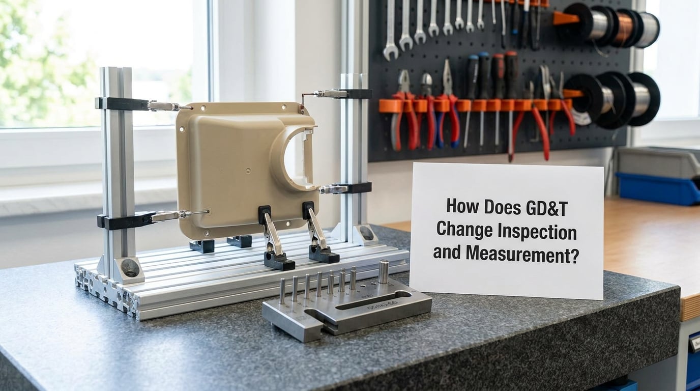
GD&T changes what the inspector is allowed to do, because the drawing now names the setup. The measurement method is free to vary; the setup and the simulated datums are not.
| Method | Good at | Watch out for |
|---|---|---|
| Manual gauges (calipers, micrometers, plug pins) | Quick confirmation of size, and go/no-go checks of a sealing or press-fit feature | Cannot evaluate a datum-based geometric control at all, and measurement force can deform a thin molded wall |
| Optical comparator | Fast profile and contour checks on features that can be projected, especially machined edges | Poor on translucent or textured molded surfaces, and it does not simulate a 3D datum reference frame |
| CMM | Evaluating feature control frames against a simulated datum reference frame, and reporting actual measured values | Alignment routine must mimic the real mating surfaces; probing a warm part at the wrong moment gives a number nobody can reproduce |
| Laser or structured light scanning | Fast whole-surface form data on warped covers and complex contours | Reflective and translucent surfaces need coating, and stitching error needs to stay under the tolerance you are chasing |
| Functional gauges | Verifying the thing you actually care about, such as a snap arm engaging or a seal closing | Binary result; it tells you pass or fail and nothing about how close you are |
Two conditions close most measurement disputes on polymer parts. First, measurements belong at the standard reference temperature of 23 C, with the part conditioned and stable rather than straight off the ejection cycle. A part read warm from the tool will show dimensions that no inspection lab will ever reproduce. Second, the measurement condition needs to be written on the drawing, not assumed, because the difference between free state and supported measurement is a real shape change on a thin molded part.
One practical warning about CMM output: a report showing every deviation and a green pass tells you nothing if the alignment routine does not reproduce the assembly datums. The drawing defines compliance, and the report is only evidence of it when the setup matches.
What Does a Practical GD&T Drawing Example Look Like?
Take a small injection-molded bracket that carries a circuit board and mounts to a metal chassis. Three requirements drive the whole drawing: two chassis holes on a 60 mm pattern, one board mounting boss standing 8 mm proud and square to the mounting face, and a cosmetic outer face with no leak requirement.
Datums. The mounting face becomes datum A. It is machined and carries the load, and a flatness callout of 0.1 to datum A does not make sense against itself, so the control is untoleranced form, held by ISO 2768 for the moulded surface plus a note that the face is machined after moulding. The 8 mm board boss, being a cylinder, becomes datum B, and one chassis hole becomes datum C, chosen because the mating pin sits there and it is the only feature the assembly can locate on in that direction.
Features. The two chassis holes get a size dimension of 5 plus or minus 0.1, a position control of true position 0.4 at MMC to A, B, C, and diameter 0.1. The board boss gets a position control of true position 0.3 to A, B, and perpendicularity of 0.15 of the mounting face to A. The board standoff gets a 0.2 perpendicularity to A. The cosmetic outer face gets nothing, because nothing about it is functional.
Modifiers and size. MMC on the chassis holes gives a real bonus, because the assembly locates on a pin and a smaller hole means more clearance. RFS, the default, applies everywhere else, since the moulded boss size varies with resin shrinkage and a bonus there would be imaginary.
Inspection. The plan says: measure at 23 C after conditioning, simulate datums with a plate on the mounting face, a collet on the board boss, and a pin in one chassis hole, evaluate positions and perpendicularity on a CMM, and verify the moulded features on a first article plus a sampling plan thereafter.
Notice what is not in that drawing. No flatness on the bow-prone outer wall, no concentricity on the board boss, because position already covers it relative to A, and no profile callout on a face nobody can see in assembly. Every control exists because something in the assembly depends on it, which is the standard I would hold any plastic drawing to.
What Are Common GD&T Mistakes on Plastic Parts?
Using an ambiguous datum that nobody can simulate
A datum on a drafted wall or a textured cosmetic surface has no faithful simulator. Name a machined pad or a cylindrical feature instead, so the shop can build the same setup your assembly does.
Specifying inspection access that does not exist
Datums and features buried behind a snap arm, under an overmould, or inside a deep pocket cannot be probed. Move the control to a surface that is reachable, or add a small flat specifically intended for fixturing.
Tolerancing more features than the function needs
Each tight callout adds cycle time, sampling, and disagreement. Ask what fails if this feature moves by the full band. If the answer is nothing measurable, widen it.
Confusing position with size
A diameter callout on a hole controls only how big it is. Location comes from position against a datum, and a plus/minus dimension on the hole centre plus a diameter tolerance lets the hole wander across its whole square tolerance zone.
Ignoring moulding variation the tolerance cannot control
GD&T does not make a sink mark go away. If a region warps predictably, either design it out, fixture it to control the variation, or exclude it from functional controls and treat it as cosmetic with an agreed reference sample.
Adding RFS or MMC modifiers by habit
MMC only pays off on features of size whose variation is well understood. On a heavily filled resin where bore size swings across most of its band, the bonus tolerance is theoretical. Use MMC where fit protection is genuinely needed, and leave the rest at RFS.
Controlling flatness on a surface that was never flat
Applying flatness to a bow-prone moulded panel creates inspection arguments instead of control. Use tangent plane, use profile against a datum, or drop the control and rely on a functional test.
Specifying the resin too loosely
A drawing that says plastic or nylon and nothing else leaves shrinkage, moisture, and stiffness open, and the dispute arrives with the first lot. Name the exact resin, grade, filler, colour code, and the measurement condition. Getting these GD&T basics right for plastic parts is mostly about removing the places where two people can read the same drawing differently.
Frequently Asked Questions
Is coordinate dimensioning acceptable for plastic parts?
Yes, for simple parts with one interface and no meaningful relationship between features. Coordinate dimensioning is fine where a caliper is all the inspection will ever use. It stops being acceptable once features must work together, such as a hole pattern that locates on a pin, or a cover face that seals against bosses. There, the variation between features is what matters, and that is what position relative to a datum expresses. Add a note naming the exact resin and measurement condition either way.
What is the difference between a datum feature and a datum?
A datum feature is a real surface on your part: a pad, a boss, a hole, a slot. A datum is the imaginary plane, axis, or point that an inspector derives from that surface to take measurements from. The datum does not exist on the part and cannot be seen or touched. A datum feature simulator is the physical stand-in for the mating component, such as a plate or a pin, and it must match how the part really contacts the assembly. Confusing the three is the most common source of drawing disputes.
Does using a CMM automatically make a part GDu0026amp;T compliant?
No. A CMM measures whatever the alignment routine tells it to reference, and if that routine does not reproduce the datum reference frame on the drawing, the numbers describe a different setup than the assembly. The drawing defines compliance, not the instrument. A CMM report only becomes evidence when the datum simulators match the real mating surfaces, the part is measured at the stated reference temperature of 23 C, and the software applies the same material condition rules the drawing specifies. Hardware alone proves nothing.
How should cosmetic warpage be controlled on a molded plastic cover?
Separate the cosmetic requirement from the functional one, and handle them differently. For function, control only what the assembly depends on, such as the sealing face or the boss coplanarity, using a datum-based callout. For appearance, specify a defined reference sample, keep the surface outside tight geometric controls, and consider a tangent plane control if one direction of bow still matters. A flatness callout across a bow-prone panel measures a shape the design never intended, and only produces inspection arguments.
Should plastic part tolerances include extra allowance for shrinkage and molding variation?
No blanket allowance, and this is where drawings go wrong. Handle shrinkage where it belongs, in the CAD model through scale compensation, and state the achievable band separately from the functional requirement. Uniform scale factors cannot fix non-uniform distortion, so protect the mating interfaces with datum-based geometric controls instead of widening every dimension. Also note that ISO 2768 classes were written for metals, so a fine class on a moulded feature simply creates rejects rather than accuracy.
Conclusion
Start with the part’s functional interfaces, not with a symbol library. Identify every surface the part actually locates and seals against, choose datums that a shop can physically simulate, and apply only the geometric controls needed to protect those functions. Everything else can live under ISO 2768 or under a cosmetic note.
Before releasing the drawing, confirm two things with engineering and quality: that the moulder can commit to the tolerance band in writing at 23 C, and that an inspector can set up the datum reference frame with real hardware. Get those two answers early and the rest of the GD&T is detail. Leave them open and no amount of notation will hold the assembly together.