
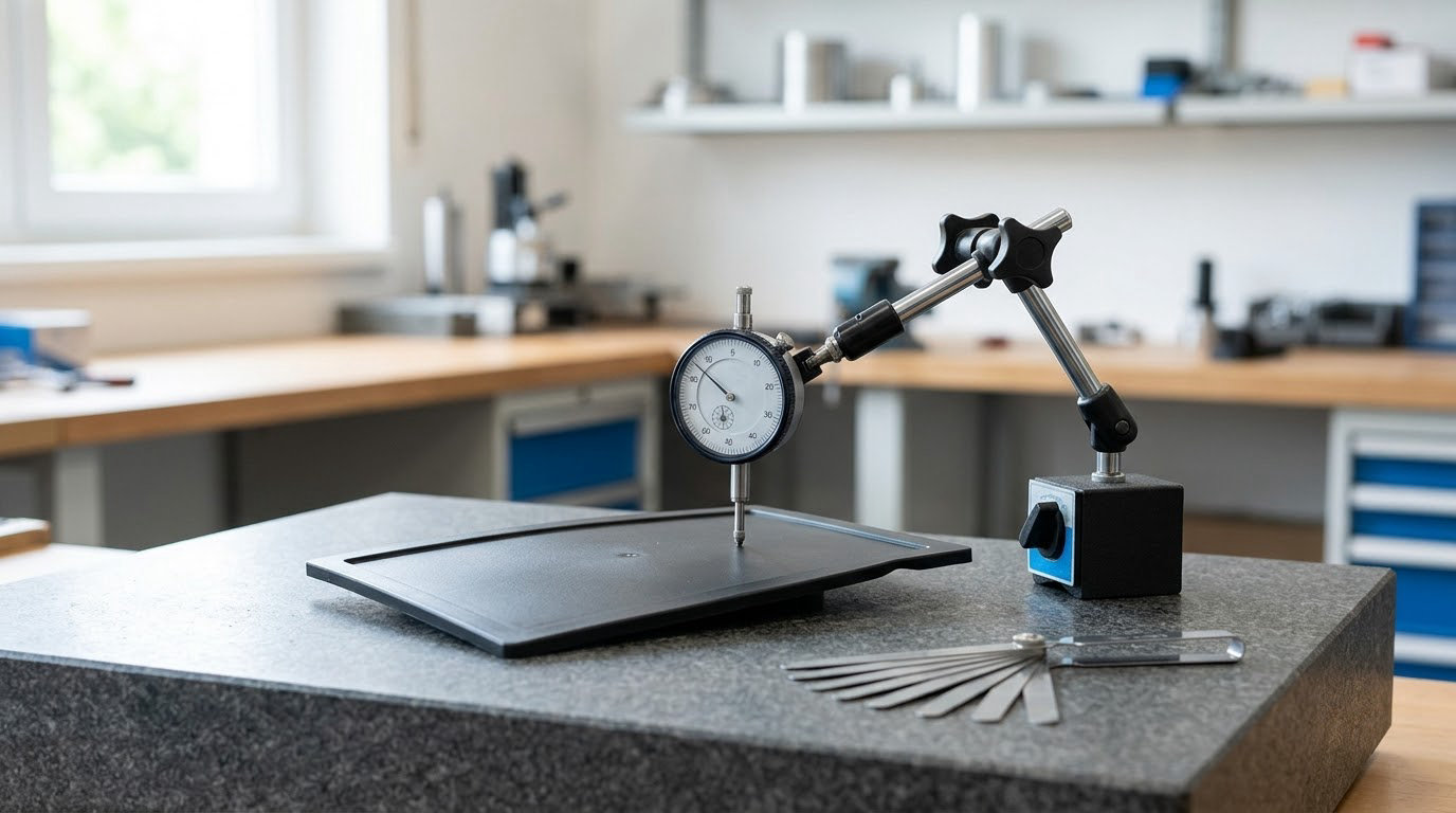
To measure warpage on a plastic part, put it into a defined measurement state on a flat reference surface and read how far it departs from the nominal geometry. A precision straightedge and feeler gauge covers routine checks, a dial indicator swept across a granite plate gives a full-field number, and a 3D scan compared against the CAD model gives a deviation map.
Most warpage arguments are not molding problems. They are measurement problems. A part measured free when it is actually designed to sit clamped in service will read out of tolerance even though it assembles correctly, and a part read straight off the machine will give a different number on every shift.
Warpage is the distortion of a molded part out of its intended flat or straight shape. It shows up as a gap under a straightedge, a bow when the part rocks on a plate, or a twist you notice when you sight along an edge. It exists because the part contracts unevenly as it cools, and the residual stress that builds up keeps relaxing for days after ejection.
Table of Contents
- What You Need Before You Start
- Step-by-Step: How to Check Warpage on a Plastic Part
- Frequently Asked Questions
- What instrument is best for measuring warpage on a molded plastic part?
- Is straightedge and feeler gauge testing accurate enough for plastic parts?
- How much warpage is acceptable for a plastic part?
- Can warpage be measured without destroying the part?
- What is the difference between warpage and sink marks?
- How should automated production measure plastic-part warpage?
- Conclusion: Fix the Datum Before You Fix the Gauge
What You Need Before You Start
Four things have to exist before a gauge touches the part: the nominal geometry, a defined datum, a controlled environment, and an instrument that can resolve the tolerance you actually need to hold. Miss any one of them and the number you get is not evidence.
- Drawing or CAD model. The nominal surface the part is supposed to have. Without it you are only measuring how a part looks today.
- A defined datum and tolerance. The plane or surfaces the part is referenced from, and the flatness, profile, bow or twist limit it must satisfy.
- A controlled environment. A room near 23 °C and 50% relative humidity, and parts that have sat there long enough to stabilize.
- A clean, unmarked part. Dust, mold release, labels and burrs all change a feeler reading.
- The right instrument. Straightedge and feeler gauges, a dial test indicator with a granite surface plate, a height gauge, a CMM or a 3D optical scanner.
Match the instrument to the tolerance rather than the other way round. If the drawing permits 0.5 mm of out-of-flatness, feeler gauges settle that argument without anyone raising their voice. If it permits 0.05 mm, you need a dial indicator and a granite reference, or an optical system.
Decide the measurement state before you start, and write it down. A free-state reading shows the part as molded. A clamped-state reading shows the part as it behaves in its assembly, and for optical covers, lenses and sealing faces the clamped number is usually the one that predicts fit.
Step-by-Step: How to Check Warpage on a Plastic Part
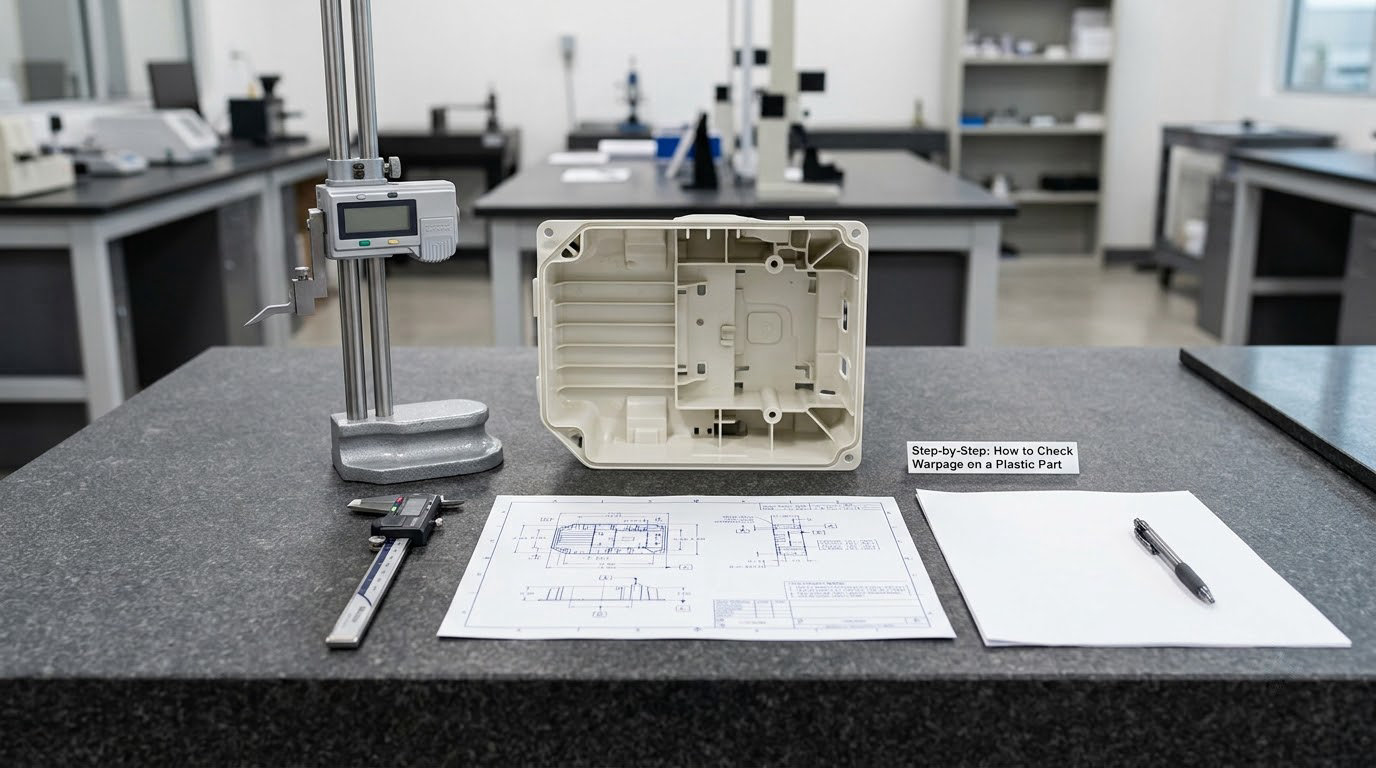
- Confirm the datum, the nominal surface and the warpage tolerance on the drawing or model.
- Condition the part to a stable temperature, usually 24 hours near 23 °C and 50% RH.
- Clean the part and handle it by its frame, never by a thin wall or a snap feature.
- Seat the part on three or more defined supports, or in the specified clamping fixture.
- Zero the instrument on a reference surface that is flat by definition, such as the granite plate.
- Read deviation at multiple locations: corners, mid-span, along both diagonals and across critical features.
- Repeat the sweep in a second orientation to separate bow from twist.
- Record the values with units, instrument, calibration date and measurement state attached.
1. Define the Datum and Warpage Acceptance Criteria
Warpage is only meaningful against something. Start by identifying the functional seating surfaces or the datum plane the drawing intends, then establish the nominal geometry from the model rather than from a healthy sample that happens to be running.
Next, establish what kind of deviation the drawing actually calls out. Flatness controls how far any point sits from a plane. Profile controls the whole outline. Bow is a curvature along one axis, twist is a rotation about the long axis, and out-of-profile covers a general departure from the nominal shape. Each is measured differently and reported differently.
If the drawing shows a flatness frame but does not identify the datum plane, stop and get engineering to state it in writing. An inspector picking a convenient reference surface is the single most common source of false rejects. The rules that decide which deviations control and which are subordinate are covered in our guide to plastic part tolerance standards.
2. Condition and Position the Part Consistently
Polymers keep moving after they leave the mold. Let parts condition near 23 °C and 50% relative humidity before you read them, and use a fixed dwell time for every inspection so the comparison is fair. For production parts, a day of conditioning is a reasonable default; for first-article work, use the T1 sample set measured under the same protocol every time.
Handling matters as much as temperature. Grip the part by its frame or a rib, never by a wall, a lens face or a snap-lock arm. A part squeezed in a hand can hold a bend long after it has left your fingers.
Position the part on three or more defined supports, or in the fixture that represents assembly. Support at a corner and the part rocks; the reading then depends on where your hand happened to be. Reproduce the same orientation for every part in the run.
3. Choose the Right Measurement Method
Choose the method from three inputs: how tight the tolerance is, how large the part is, and how many parts you have to inspect. A method that resolves 0.1 mm is useless on a 0.02 mm limit, and a scanner that takes four minutes per part will never survive a press-side screening job.
The practical ladder runs like this. A precision straightedge and feeler gauges suit large, flat, forgiving parts in low volume. A dial indicator on a granite plate suits production screening and routine acceptance. A height gauge suits quick point checks where only a few features matter. A CMM or 3D optical scanner suits tight tolerances, complex shapes and anything you need to correlate against simulation.
Part geometry drives the choice more than budget does. Thin-wall trays warp in ways a straightedge can actually see, while fiber-reinforced housings need enough resolution to separate a normal reading from a resin-rich region. Our notes on wall thickness rules for plastic part design explain which features tend to distort first.
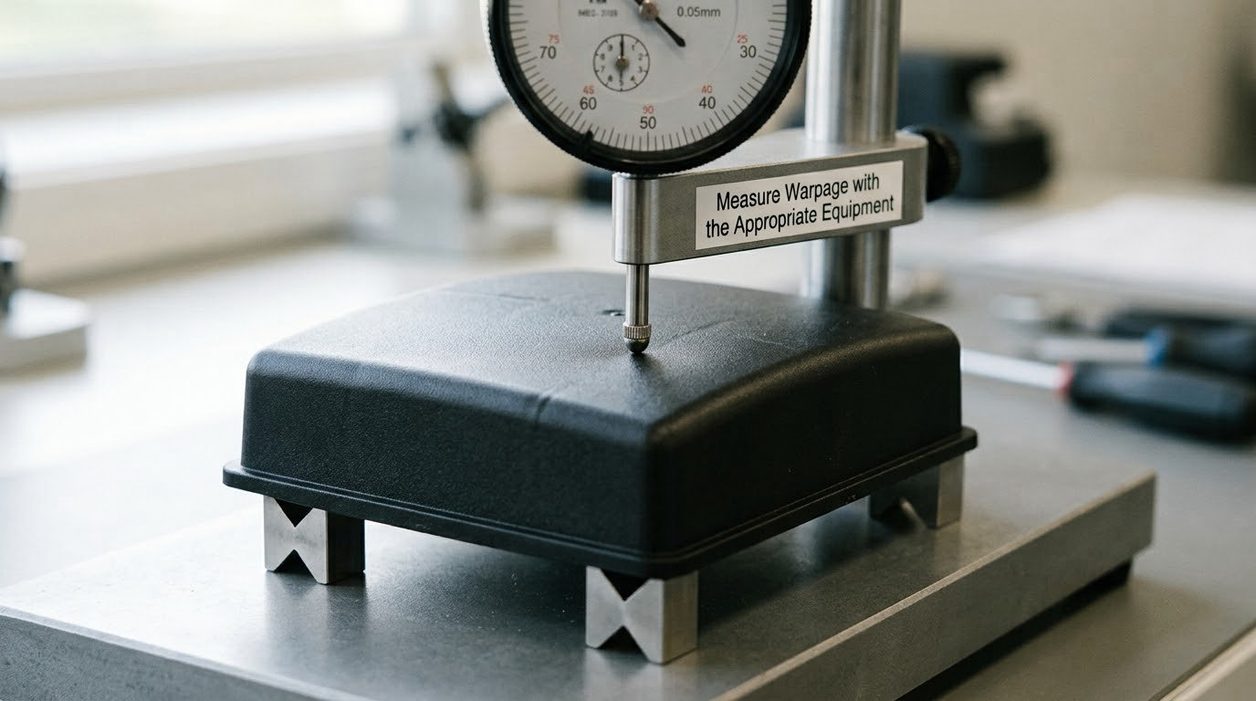
4. Measure Warpage with the Appropriate Equipment
Straightedge and feeler gauges. Place the knife edge along the diagonal, the long axis and the short axis in turn. Where the part bows away from the straightedge, slide the feeler set into the gap until it just drags. That reading is the peak-to-valley deviation along that line. Keep the straightedge loaded lightly; press hard and you will measure your hand.
Dial test indicator on a granite surface plate. Zero the indicator on the plate, seat the part, and sweep the contact point in a grid across the surface. Recording deviation at multiple locations, rather than at one, is what turns a single number into a map of where the part is bent. Sweep corner to corner, then repeat along the diagonals, and you will see bow and twist separately.
Height gauge. Take a handful of point readings referenced to the datum plane. It is fast and repeatable, and it is the right tool when three or four features decide the pass or fail.
CMM and 3D optical scanner. Scan the part, best-fit align it to the CAD model, and the software returns a full-field deviation map. For a round part, report the warp as an angle over a stated length or as radial deflection, which is how drawings for circular features usually specify it.
Optical metrology vendors make a related point worth stealing: one scan can be evaluated both unclamped and with virtual clamping points applied, so a single acquisition gives you the free-state and the as-installed answer. A real clamp fixture does the same job mechanically, by holding the part in an overdetermined state closer to how it is screwed down in service.
One open practitioner question is worth answering here. A 2016 Autodesk Moldflow Insight forum thread asks how to measure deflection at the snap lock on a 200 x 200 x 3 mm lid, and it never got a reply. Measure the snap-lock region against a machined reference surface that sits at the mating plane height, read the gap between the part and that reference, and express it as a linear deflection and as an angle over the run from the edge to the lock.
5. Calculate and Check the Result
Compare the deviation against the drawing, in the dimension the drawing uses. If the note says millimetres, report millimetres. If it says degrees over a length, compute it that way: divide the measured rise by the run and convert.
Keep the report honest about what was measured. Peak deviation is the worst single point. Peak-to-valley is the total range from the high spot to the low spot, and it is the figure most flatness callouts mean. Bow is a single curvature, twist is a cross-rotation between two ends, and out-of-profile is the general departure from the nominal outline.
Do not mix warpage up with a size error or a thickness change. A uniform shrinkage moves every dimension in the same direction and is calculated from the mold dimension against the part dimension. Warpage is a shape distortion that a caliper will happily miss. The distinction between profile, flatness and datum control is set out in our primer on GD and T basics for plastic parts.
Judge against function as well as the number. A lid that seats with 0.3 mm of bow is usually fine. A cosmetic cover that shows a highlight line across a painted face is not, at any tolerance the drawing happens to carry.
6. Document, Investigate, and Verify the Part
Write down the part number and lot, the instrument and its calibration status, the datum setup, the room temperature and humidity, the conditioning time, the measurement state, every reading, and the pass or fail call. A warpage result without its state is close to meaningless.
Where the part is borderline, measure it twice and then hand it to engineering. Repeat readings from a second operator are the cheapest way to expose a setup problem, and a part that reads differently every time usually points at conditioning, support points or handling rather than at the mold.
Run a simple repeatability check when you set the method up: ten parts, two operators, two sessions. If the gauge cannot separate conforming from nonconforming parts, it will generate false rejects forever, and the shop will stop believing the inspection.
Common Mistakes to Avoid
- Measuring from an undefined surface. A reading without a stated datum cannot be defended. Fix the reference first.
- Pressing too hard with the straightedge or clamp. You will flatten the very warp you are looking for and under-report it.
- Checking a single location. One point tells you nothing about bow or twist. Sweep a grid and both diagonals.
- Confusing dimensional error with warpage. Shrinkage and flash are size and edge conditions; warpage is shape.
- Reading before thermal stabilization. A warm part reads differently every hour, which destroys trust in the gauge.
- Declaring acceptance without a tolerance. There is no universal number that counts as acceptable warpage; the limit comes from the drawing and from function.
Frequently Asked Questions
What instrument is best for measuring warpage on a molded plastic part?
A dial test indicator swept across a granite surface plate is the sweet spot for routine inspection: it resolves a few hundredths of a millimetre and takes seconds per part. A height gauge works when only a few point readings matter. A coordinate measuring machine or 3D scanner earns its place when the tolerance is tight, the part is large or complex, or you need a full-field deviation map.
Is straightedge and feeler gauge testing accurate enough for plastic parts?
It is accurate enough for large, relatively flat parts with clearly defined datums and forgiving tolerances, which covers a lot of housings, lids and trays. It is less reliable on thin or flexible parts, because the part can rock or get pushed flat by the straightedge. When a part looks marginal, confirm it with a dial indicator before anyone scraps it.
How much warpage is acceptable for a plastic part?
There is no universal acceptable value. The limit is set by what the part has to do in service: an optical cover needs far less deviation than a cable tie. Judge the part against its drawing, its CAD model and its functional requirements. Where the drawing is silent, have engineering define a limit from fit, appearance and assembly behaviour rather than from whatever the shop gauge can read.
Can warpage be measured without destroying the part?
Yes. Straightedges, dial indicators, coordinate measuring machines, structured light scanners, laser scanners and computed tomography are all nondestructive methods. The risks are indirect: a clamping fixture can mark or distort a thin part, and a heavy fixture can flatten a warp you were trying to measure. Handle the part by its frame, not by a thin wall or a snap feature.
What is the difference between warpage and sink marks?
Warpage is a broad distortion of shape, where the whole part bows or twists away from its nominal plane. Sink marks are localized depressions, usually a few millimetres across, that form where a thick section feeds material and the surface pulls inward under hold pressure. One is read across the part against a reference plane; the other is read as a depth relative to the surrounding surface.
How should automated production measure plastic-part warpage?
Use a repeatable fixture, fixed camera or scan coordinates, calibrated sensors and a measurement routine tied to the engineering datum. Validate the setup with a gauge study before trusting the numbers. If repeatability and reproducibility cannot separate conforming from nonconforming parts, automation only produces unreliable data faster, and the false rejects come with it.
Conclusion: Fix the Datum Before You Fix the Gauge
Start here. Get the nominal geometry and the tolerance in front of you, define the datum the deviation is measured from, condition and support the part the same way every time, and pick an instrument that can actually resolve the limit you have to hit.
Then repeat the setup under controlled conditions and keep the objective data: instrument, calibration date, state, readings, decision. That record is what separates a real quality problem from a measurement argument, and it is usually the cheapest fix available when a shop starts scrapping good parts.