
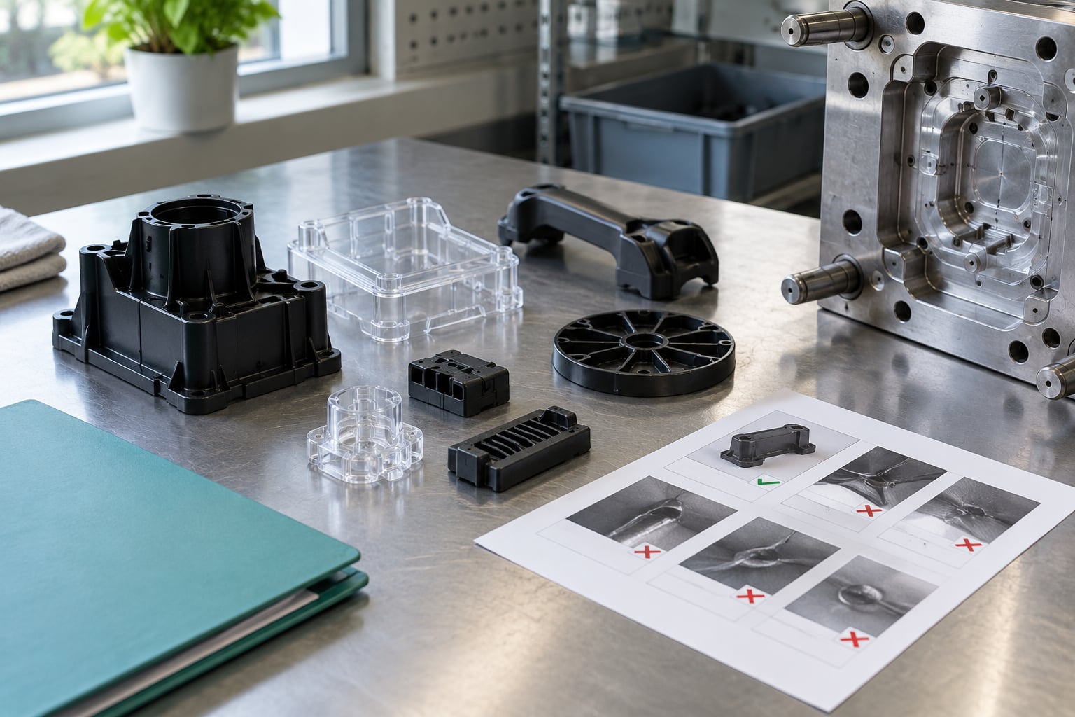
Injection molding defects are unintended imperfections in molded plastic parts, caused by how the melt flows, packs, and cools rather than by any single faulty machine. The most common are short shots, flash, sink marks, weld lines, warpage, flow marks, voids, and burn marks. This injection molding defects chart and fixes guide maps each symptom to its likely machine, mold, or material cause so you know who owns the problem before anyone changes a setting.
A defect chart is a starting point, not a diagnosis. Two defects that look identical on the bench can come from opposite ends of the process, so the real skill is working through them in a fixed order and changing one variable at a time.
Start with the ten defects that cause the most scrap hours on a typical production floor: short shot, flash, sink mark, weld line, flow mark, jetting, burn mark, warpage, void, and silver streak. The chart below covers those plus the appearance defects that pass inspection and then fail in the customer’s hands.
Table of Contents
- What You Need
- Injection Molding Defects Chart and Fixes at a Glance
- Step-by-Step: How to Diagnose and Fix Injection Molding Defects
- Step 1: Confirm and Classify the Defect
- Step 2: Check Material Preparation, Where Many Injection Molding Defects Start
- Step 3: Review Injection and Hold Parameters
- Step 4: Inspect Gate, Runner, and Cavity Conditions
- Step 5: Check Venting, Cooling, and Mold Alignment
- Step 6: Make One Controlled Change and Retest
- Step 7: Verify the Fix and Prevent Recurrence
- Common Injection Molding Defects and Fixes
- Common Mistakes When Troubleshooting Defects
- Frequently Asked Questions
- Conclusion
What You Need
You cannot fix what you have not identified, so gather the evidence before touching the machine. Most troubleshooting goes wrong in the first ten minutes because someone adjusted a temperature based on a guess.
- Physical samples. At least three affected parts from the same run, kept in a bag so they do not get handled into a different condition. A single part tells you almost nothing.
- A known-good part. One part from before the problem started, from the same cavity and the same lot of resin if possible.
- Process records. Cycle time, fill time, transfer time, peak pressure, hold pressure, hold time, cushion, screw recovery time, and the barrel zone temperatures for every zone plus the nozzle.
- Material records. Resin grade, lot, drying temperature and dwell time, regrind percentage, masterbatch addition rate, and how long the hopper has been open.
- Basic inspection tools. A caliper or micrometer, a feeler gauge for flash land contact, a flashlight or borescope for cavity inspection, and a bench surface where parts can sit undistorted.
- Reference dimensions. The drawing or the last approved first-article report, including the critical-to-quality dimensions your customer actually measures.
A 10x loupe is worth more than people expect. Flow marks, hesitation, and stress whitening are much easier to sort out under magnification than on the mold floor.
Injection Molding Defects Chart and Fixes at a Glance
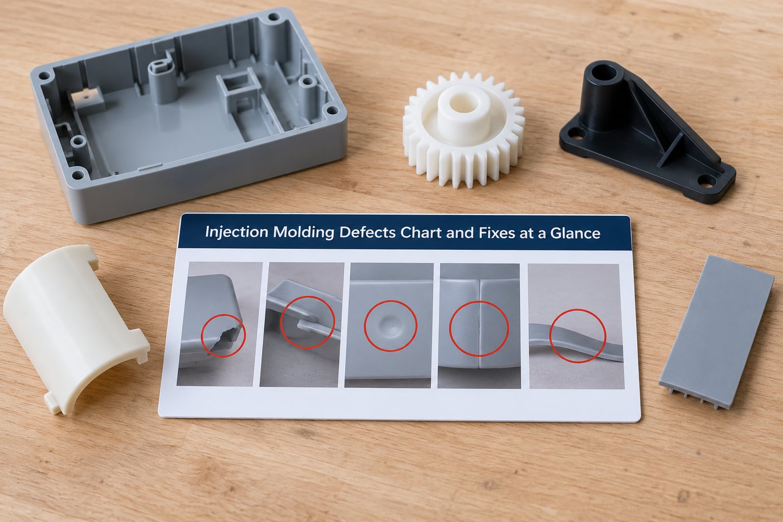
This is the chart to keep at the molding cell. Find the row that matches what you see, then work the right-hand column only after you have ruled out the causes to its left.
| Defect | What it looks like | Where it appears | Likely causes | First fix to try |
|---|---|---|---|---|
| Short shot | Part is incomplete, unfilled, or a thin sliver off the far end | End of flow, thin sections, far from the gate | Melt volume or pressure too low, melt too cold, premature freeze, poor venting, blocked or undersized gate, unbalanced flow | Confirm fill weight, then raise melt temperature or injection pressure in small steps |
| Flash | Thin sheet of extra material along a seam or edge | Parting line, shutoff faces, worn mold edges, vent | Excess cavity pressure, worn flash land, mold not closing fully, misaligned vent, clamping force too high | Check flash land contact with a feeler gauge before changing any pressure |
| Sink mark | Shallow depression or dimple on a surface | Near thick sections, ribs, bosses, and gate areas | Thick wall, hold time or hold pressure too low, not enough cooling, wall thickness varies too much | Extend hold time and confirm hold pressure, then look at the wall design |
| Void or bubble | Hollow pocket inside the part, often visible as a silver bubble on the surface | Center of thick sections, behind bosses | Trapped air, moisture, thick section, poor venting, back pressure too low during fill | Check drying and venting together; the two causes look identical from the outside |
| Short packing | Part is light for its size and dimensions shrink after cooling | Measured across the whole part | Hold pressure or hold time cut short, cushion too small, nozzle or check valve leaking, shot size too small for the part | Measure part weight against the standard; if it is low, work on the hold phase |
| Weld line | Seam or crease where two flow fronts met, sometimes raised and weak | Where melt splits around a hole or obstacle and rejoins | Multiple flow fronts, low melt or mold temperature, poor venting at the joint, slow fill | Raise mold temperature and vent depth at the joint |
| Flow or hesitation mark | Curved streak or gloss difference on the surface | Starting at the gate, curving across the face | Freeze layer on the melt front, mold too cold, injection speed too low, resin regrind in the mix | Increase injection speed and mold temperature |
| Jetting | Start of the flow is a rounded, rippled knot rather than a flat fan | At the gate entry, especially on cosmetic faces | Small gate, long tunnel, restricted entry, melt front entering as a rope instead of a sheet | Move or enlarge the gate, or change gate type |
| Burn mark | Dull brown or black discoloration, usually at the end of fill | Last area to fill, near the end of a long flow path | Trapped compressed air, no or shallow vents, melt temperature too high, resin degraded | Clean or deepen the end-of-fill vents, then recheck melt temperature |
| Warpage | Part comes out curved, twisted, or out of flat | Whole part, worst at thin ribs and corners | Uneven cooling, residual stress, uneven wall thickness, asymmetric packing, hot spots, ejection force | Balance cooling on both sides and check the mold for hot spots |
| Silver streak or splay | Streaks of tiny bubbles running with the flow | Anywhere, often worst near the gate or on the last shot material | Moisture in the resin, trapped air, contamination, degraded melt, oil or grease on pellets | Verify actual drying time and temperature, not what the set sheet says |
| Cold slug | Flat disc or lump of un-melted resin attached near the gate | At the sprue, cold slug well, or the first part after a restart | Cold slug well not deep enough, nozzle cold, material sitting in the nozzle too long | Deepen or enlarge the cold slug well and set nozzle temperature correctly |
| Stringing or nozzle drool | Thin string of plastic trailing from the nozzle, or a whisker on the part | Nozzle tip, sprue, gate | Melt too hot, nozzle too hot or too long, decompression off, check valve leaking | Add decompression and drop nozzle temperature a zone |
| Ejector pin marks or drag marks | White rings, scuffs, or drag lines where the part rubs the mold | Ejection areas, walls with undercuts, drafted surfaces | Insufficient draft, no lubricant, rough cavity, pin imbalance, part sticking | Check draft and cavity finish before adding release agent |
| Delamination | Peeling or flaking surface layer on the part | Large flat faces, thick sections | Contaminated regrind, incompatible polymers, entrapped moisture between layers, over-drying heat | Audit the regrind stream and its contamination history |
| Discoloration or marbling | Uneven color, swirls, or dark specks through the part | Throughout the part, often uneven in thickness | Poor masterbatch dispersion, mixed grades, contaminated regrind, resin held too long in the barrel | Verify masterbatch ratio and mixing, then check the regrind ratio |
| Dimensional out of tolerance | Measurements drift between parts or change after a few minutes | Any critical dimension | Inconsistent packing, moisture variation, mold temperature swing, cavity wear, varying wall thickness | Measure every part and treat the variation, not the single outlier, as the defect |
Two rows in that chart get confused more than any other pair, so it is worth being precise. A void is trapped gas or moisture inside the part and usually shows a bubble or a silver streak on the surface. A sink mark is the surface itself pulling inward because the material underneath shrank while cooling. If you can push a fingernail into a depression, it is a sink. If it is a bubble under a surface that still feels smooth, it is a void.
Step-by-Step: How to Diagnose and Fix Injection Molding Defects
Run this sequence in order every time. It takes longer for the first few defects you ever chase and much less time for the ones after that.
Step 1: Confirm and Classify the Defect
Compare the suspect parts against a known-good part under the same lighting. Look at where the defect sits: near the gate, at the end of fill, on a thick section, on a drafted face, or in the same place on every part in the box.
Location is the most useful clue you have. A defect in the same place on every part usually points to mold geometry, a hot spot, or a gate issue. A defect that moves around, or that shows up only on some parts, points to material, venting, or a random event such as a gas pocket.
Then rule out damage that happened after molding. Ejection, handling, and assembly all leave marks. A scratch that appears only on parts that have been through the cell downstream is not a molding defect at all.
Step 2: Check Material Preparation, Where Many Injection Molding Defects Start
Hygroscopic resins absorb moisture from the air, and wet pellets produce steam the instant they enter the barrel. That is where silver streaks, bubbles, splay, reduced strength, and dimensional inconsistency come from.
- Verify real drying conditions, not the set sheet. Check the dryer temperature at the material, not the dial setting, and time how long the hopper has been running. Under-drying is far more common than over-drying.
- Check exposure. Anything left in an open hopper, a humid staging area, or a night-shift refill that sat uncovered can defeat a correctly sized dryer.
- Confirm the resin grade. A lot change without a trial can bring a different melt flow rate and a different drying requirement with it.
- Audit the regrind ratio. Too much regrind, or regrind with a different degradation history, causes brittleness, discoloration, and inconsistent flow.
- Check masterbatch mixing. Poor mixing gives marbled color and inconsistent gloss rather than a uniform tint.
Moisture in a nylon part also shows up as reduced tensile strength, not just as a cosmetic streak, so a mechanical failure traces back here more often than anyone expects.
Step 3: Review Injection and Hold Parameters
Pull the current machine recipe and compare it with the last good one. A single changed value is often the whole story.
- Fill speed and peak pressure. Too low and the melt freezes before the cavity fills, so you get short shots and hesitation marks. Too high and the melt front traps air, which burns at the end of fill.
- Transfer time and position. Switching from velocity control to pressure control at the wrong moment changes packing and part weight.
- Hold pressure and hold time. Hold pressure too low or hold time too short gives sink marks, voids, short packing, and low part weight. Holding past the point where the gate seals adds cycle time with no benefit.
- Cushion. Too little cushion means the screw bottoms out and loses the ability to hold pressure consistently.
- Cooling time. Too short means the part is ejected hot, which warps it and makes the next defect harder to see.
Work out whether the defect scales with the shot. If flash grows when you raise pressure but short shots appear when you lower it, the problem is a balance between fill and pack, not a single setting.
Step 4: Inspect Gate, Runner, and Cavity Conditions
Get eyes on the mold. Look for the conditions below with the mold open and the part removed, and note anything you find before you close it up again.
- Gate condition. A blocked, undersized, or damaged gate starves the cavity and produces short shots and hesitation marks right at the entry.
- Runner balance. Cavities that fill at different rates produce different part weights and different degrees of packing in the same shot.
- Cold slug wells. A well that is too shallow or too narrow leaves a visible cold slug on the sprue or the first part after a restart.
- Air traps. A pocket at the end of a blind core is a burn mark waiting to happen, because the air has nowhere to go.
- Cavity pressure variation. A worn or uneven cavity changes fill pattern and wall thickness without anything visibly broken.
- Wall thickness. A step of more than roughly 15 to 20 percent in wall thickness is a defect source on its own, and no setting fixes it.
Ribs should be around 50 to 60 percent of the adjacent wall thickness. A rib as thick as the wall behind it just creates a thick section and a sink mark you cannot pack out.
Step 5: Check Venting, Cooling, and Mold Alignment
Air at the end of flow has to go somewhere. If the vent is blocked, buried, or too shallow, the melt has to compress that air instead of displacing it, and the result is a burn mark.
- Vent depth and location. Vents belong at the end of fill, at weld line joints, and behind cores. Clean carbon deposits with a brass brush, never steel, and check that vent land contact is correct.
- Cooling channel balance. Channels that do not reach the last areas to solidify leave hot spots, and hot spots cause both visible sink marks and warpage that shows up hours later.
- Water temperature and flow. A circuit that is warm on one side and cool on the other twists the part no matter how good the pack looks.
- Mold closure and alignment. Check the parting line for misalignment, debris, and worn shutoffs with a feeler gauge. Flash that appears only on one side is very often a mold alignment problem, not a pressure problem.
Parts that stick and drag on ejection are usually a draft, finish, or cooling problem. Adding release agent hides it for a few hours and then the part starts arriving out of tolerance.
Step 6: Make One Controlled Change and Retest
Write down the original setting before you touch anything. Change one variable, hold everything else, and run enough cycles to see a real effect. A two-degree mold temperature shift needs a dozen shots to show up, not one.
Label the samples the same way every time, with cycle number, date, and the single change you made. That label is what turns a set of trial parts into a controlled trial instead of a guessing game.
Keep the good parts from each trial. When you find a setting that works, you want a sample you can point at while the mold is still set up that way.
Step 7: Verify the Fix and Prevent Recurrence
Confirm the fix on appearance, part weight, and the critical dimensions from the drawing, not just on the one dimension you were chasing. Check a sample again after a cooling period, because some defects only show up once the part has fully cooled and released its stress.
Then write it down. Update the setup sheet with the setting you changed, the defect it fixed, and the trial conditions. Add a line to the control plan so the next operator knows what a good part looks like and what to do if it stops looking that way.
Change control is what separates a fix from a coincidence. Without it, the same defect comes back in six months with a different part number attached to it.
Common Injection Molding Defects and Fixes
Each of these entries gives the range of causes, because the same appearance almost never has one universal explanation. Work the fixes in the order given.
Short Shots and Incomplete Fill
A short shot means the cavity did not fill completely before the melt froze. Insufficient melt volume or pressure, a cold melt, poor venting at the end of flow, a blocked or undersized gate, and unbalanced cavities all produce the same picture.
Check the fill weight first, then the pressure profile, then melt temperature, then venting, then gate size and cavity balance, in that order. If the part is not short but the end is ragged, that points to venting rather than volume. If only the first part after a restart is short, the nozzle or barrel was not at temperature yet. Our short shot troubleshooting guide for molders goes deeper on the fill-side cases.
Flash and Part-Line Separation
Flash is extra material escaping past the parting line or a worn shutoff. Excess cavity pressure, worn tooling, a mold that does not close fully, damaged shutoffs, excessive clamping force, and a misaligned vent all cause it.
Inspect the flash land first and check closure with a feeler gauge. Our guide to preventing flash in injection molding covers the mold-side conditions in more detail. Flash that grows only at the end of fill often means trapped air is forcing the halves apart, which is a venting problem wearing a flash costume.
Sink Marks and Voids
Both come from shrinkage, but they act at different times. A sink mark is a surface depression caused by a thick section cooling faster at the skin than the core, so the core keeps pulling inward. A void is a cavity left behind by trapped gas or by material that shrank without something feeding it.
Thick sections, long hold times, high packing pressure, insufficient cooling, and uneven wall thickness all feed sink marks. Start by redesigning the thick area, then balance hold and cooling, then verify pressure and cooling conditions. If the depression is at a corner or a boss, the wall behind it is the problem and a longer hold will only delay it. What causes sink marks in injection molded parts walks through the geometry cases.
Weld Lines, Flow Lines, and Burn Marks
These three are all about how the melt front behaves, and they get mixed up because all three can appear on a cosmetic face.
A weld line forms where the flow front splits around a hole or insert and rejoins. It is a structural feature, not just a cosmetic one, because the molecules in that seam are weaker. Lower melt and mold temperature, poor venting at the joint, and a slow fill all widen it.
A flow line is the freeze layer of the previous shot showing through, usually as a curved gloss difference starting at the gate. Higher injection speed and mold temperature clear it, and excess regrind makes it worse.
A burn mark is compressed air and degraded polymer at the very end of fill, and it will not go away by raising pressure. Deepen the end-of-fill vents first, then recheck melt temperature. If it returns with clean vents, the resin is sitting too long in the barrel and degrading.
Warpage, Silver Streaks, and Dimensional Variation
These three share a root cause family: the part is not cooling the same way twice in a row. Warpage comes from uneven cooling and residual stress, silver streaks come from moisture or contamination, and dimensional drift comes from inconsistent packing.
For warpage, balance the cooling circuits and check for hot spots before touching the process. For silver streaks, verify the actual drying time and temperature, not the set sheet, and inspect the hopper for exposure. For dimension, measure every part in a sample and look at the spread across the sample. Consistent variation and random variation have different causes, and treating them the same wastes a week.
Semi-crystalline polymers like polypropylene and nylon shrink more and behave differently from amorphous ones like ABS and polycarbonate, so the same molding recipe will not transfer between them. A mold that is fine for ABS can warp polypropylene badly because the shrinkage rates are not the same.
Common Mistakes When Troubleshooting Defects
These habits cost more time than the defects do.
- Changing three settings at once. You will not know which one worked, and the next person has no record to follow. Change one, record it, retest.
- Judging from a single part. One short shot out of forty is noise. Look at a run of parts, and weigh them.
- Replacing the mold before reviewing the process data. If the defect appeared after a resin lot change or a speed increase, the mold is the least likely explanation. Check what changed first.
- Ignoring material history. Drying time, regrind ratio, and hopper exposure explain a surprising share of streaking, discoloration, and dimensional complaints.
- Adding release agent to solve a draft problem. It lowers friction for a while and hides the real cause, which then reappears as parts arrive stuck or out of tolerance.
- Ignoring the mold while chasing the machine. A blocked vent and a dirty cold slug well look identical on the part. Open the mold before the recipe.
- Never recording the fix. The same defect gets rediscovered from scratch on the next shift change or the next production job.
The fastest route to a working part is almost always the slowest route to a first guess: read the records, open the mold, change one thing, write it down.
Frequently Asked Questions
What are the defects of injection molding?
The most common injection molding defects are short shots, flash, sink marks, weld lines, flow marks, jetting, burn marks, warpage, voids and bubbles, silver streaks, cold slugs, and dimensional variation. They come from melt flow, packing, cooling, venting, mold design, and material handling. Appearance defects affect cosmetics; short shots, voids, and warpage also affect function and scrap rate.
What is injection molding?
Injection molding melts plastic pellets in a screw barrel, injects the melt under pressure into a steel mold cavity, holds it under pressure while it cools and solidifies, then ejects the part. Because the whole cycle is flow, pressure, temperature, and time, most defects trace back to one of those four things happening outside its normal window.
What are sink marks in injection molding?
Sink marks are shallow depressions on a molded surface, usually near a thick section, rib, or boss. They happen because the core of a thick area keeps cooling and shrinking after the surface has already set, pulling the skin inward. Fixes include extending hold time, confirming hold pressure, improving cooling balance, and redesigning thick sections rather than packing harder.
What are the three types of moulding?
The three main molding types are injection molding, blow molding, and compression molding. Injection molding forces molten plastic into a cavity under pressure. Blow molding inflates a parison inside a heated mold. Compression molding presses a charge between heated platens. Transfer molding sits alongside these and moves melt from a heated pot into a cold cavity.
How do you fix short shots in injection molding?
Start by checking the fill weight, then the pressure profile, then melt temperature, then venting at the end of fill, then gate size and cavity balance. If only parts produced after a restart are short, the barrel and nozzle were not at temperature yet. If the fill is complete but ragged at the end, venting is the first thing to correct, not pressure.
How much hold pressure is needed to avoid sink marks and voids?
There is no universal number, because packing pressure is only a fraction of injection pressure and depends on the machine, the material, and the gate size. The practical method is to raise hold pressure in small steps and watch part weight stop changing. Once weight plateaus, the gate has sealed and more hold pressure only adds stress. Extend hold time before adding pressure, and check the cooling circuit before either.
Conclusion
The first thing to do with any injection molding defect is name it accurately and note where on the part it appears, because location narrows the cause faster than any other single clue.
After that, work material, then process, then mold, changing one variable at a time and recording the original value before you touch it. A defect chart gets you to the right shortlist; a controlled trial and a written record are what make the fix stick.
Updated for 2026.