
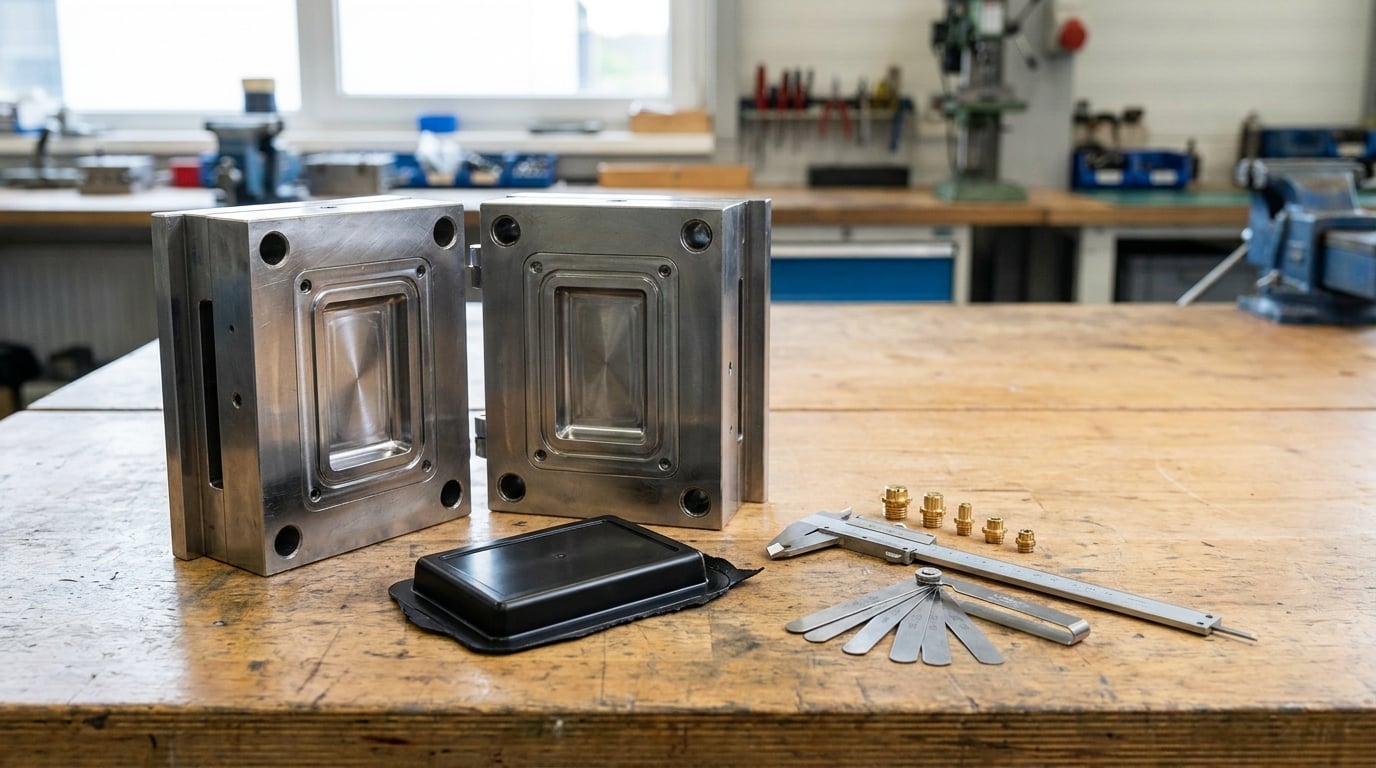
Flash is molten plastic escaping through a gap that should not exist, and preventing it takes one rule: find the gap, or find the pressure that opened it. To prevent flash in injection molding, work in order — clean and inspect the mold, confirm venting, then adjust pressure and speed one variable at a time. Most shops that fight flash lose because they reach for clamp force first and never look at the tool.
That order matters. Adding tonnage hides the symptom for a run, then the wear shows up as dents, sink marks and short shots. The fixes below take about a shift to diagnose and a short trial to verify.
Table of Contents
- What You Need: How to Prevent Flash in Injection Molding
- Step-by-Step
- 1. Identify Exactly Where the Flash Appears
- 2. Check Mold Closing Force and Alignment
- 3. Confirm Venting and Air-Trap Design
- How to Prevent Flash at the Parting Line by Correcting Pressure
- 5. Validate the Mold and Resin Condition
- 6. Run a Controlled Verification Trial
- 7. Prevent Recurrence and Update the Process
- Common Mistakes
- Frequently Asked Questions
- Conclusion: Start With the Flash Pattern
What You Need: How to Prevent Flash in Injection Molding
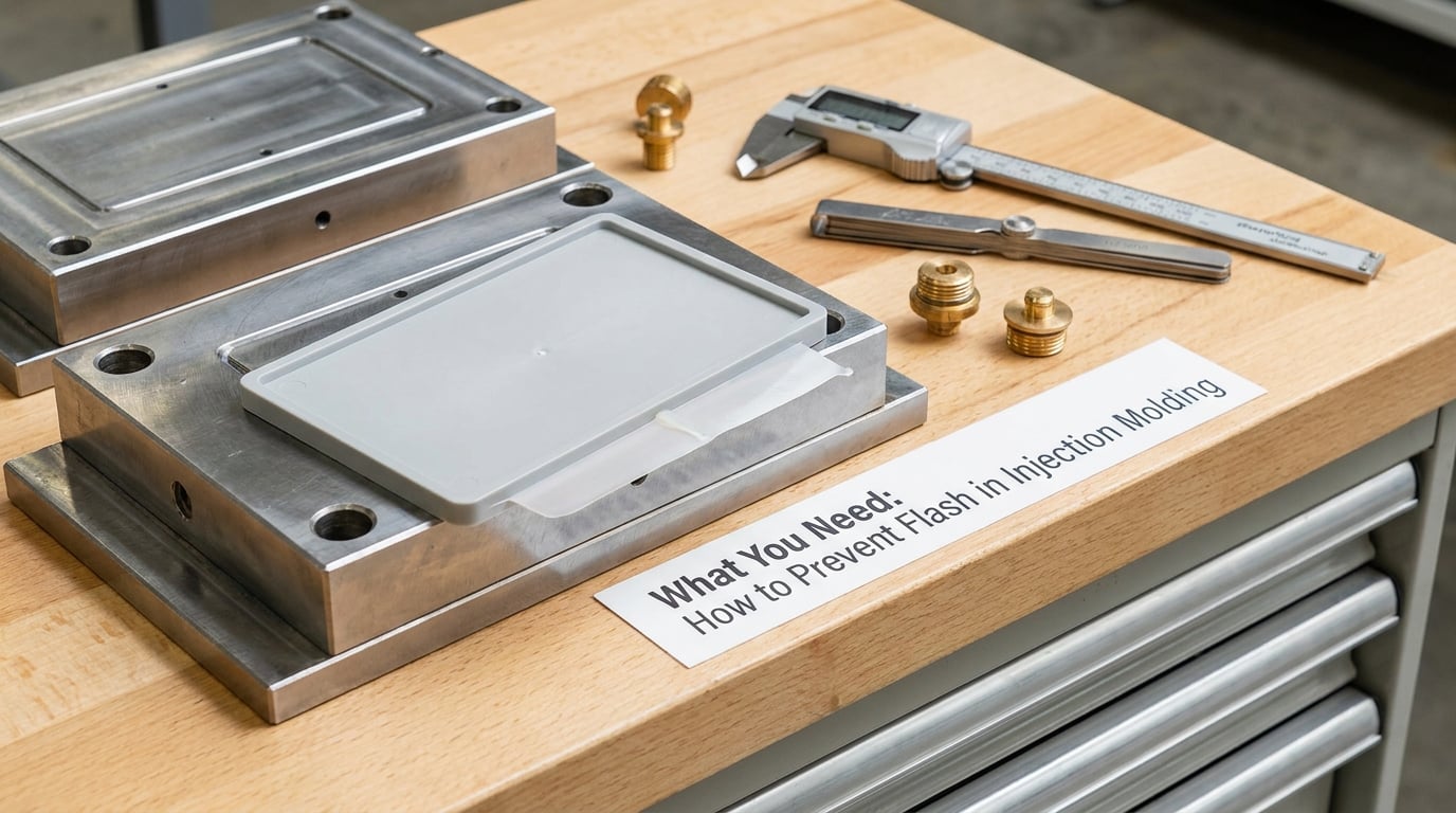
Gather this before anyone touches a setting. Half of flash calls I have seen trace back to a diagnostic that started from a number nobody had written down.
- Defect samples. Bag three to five affected parts, note the cavity, the cycle count, and whether the flash was present on the first shot off the tool or appeared later.
- Part drawing with cosmetic surfaces marked separately from functional ones, so you know which flash you can tolerate and which you cannot.
- Mold drawing or a photo of the parting line, including vent locations, insert outlines, slider travel and ejector pin positions.
- Resin data: grade, supplier, batch, drying time and temperature, moisture reading, and the regrind percentage in the mix.
- Last known good process sheet — injection speed profile, transfer position, holding pressure and time, cushion target, and the barrel zone temperatures.
- Press data: rated tonnage, machine tonnage for the part, and the projected part area in square centimeters.
- Cavity pressure capability. A pressure transducer on the hot runner or a cavity pressure sensor turns guesswork into a number. Without one, rely on the fill study and cushion behavior.
- Inspection tools: feeler gauge or shim stock, spotting paste, borescope, vent cleaning picks, brass wire, a flashlight, and the mold maker’s vent depth reference for that resin.
- A written trial plan with one variable per change and 3 to 5 shots between checks.
On a live tool you will also want the cycle time and the scrap rate before you start, so nobody argues later about whether the “fix” cost you output.
Step-by-Step
The sequence below moves from the evidence in front of you to verified corrections. Each step says what to inspect, what to change, and how to confirm the change worked. Do not skip ahead, because a pressure change made before the mold is clean will hide the real cause.
1. Identify Exactly Where the Flash Appears
Write down the flash location, the direction it points, its thickness, and how far it runs. Is it a uniform fringe around the whole parting line, or a patch at one shut-off area, around one ejector pin, or at the base of a slide core? That single split — uniform versus localized — decides where you look next.
Uniform flash around the full perimeter usually means mold parting-line fit, clamp force, or a pressure problem that affects the whole cavity. Localized flash at one spot points to a shut-off face, a worn insert, a mislocated insert, or a slide lock that is not fully engaged.
Measure what you can. A feeler gauge against the parting line should not pass a 0.02 mm shim without resistance anywhere on the seal. Thickness tells you about pressure: a fat soft fin that grows with each shot usually means overpacking, while a thin hard fin that does not change with settings usually means geometry.
| What you see | Likely cause | First check |
|---|---|---|
| Uniform fringe around the entire parting line | Mold opening under pressure, insufficient clamp, or a raised parting surface | Parting-line flatness, mold protection settings, actual tonnage |
| Flash at one shut-off area only | Worn or mis-machined shut-off face, insert gap | Spotting paste check and feeler gauge at that location |
| Soft flash around ejector pins and inserts | Pin or bushing clearance above 0.02 mm | Pin diameter, bushing wear, and any burr on the pin end |
| Flash at the end of fill, only on the last part of the flow path | Trapped air, poorly vented end of flow | Vent condition and end-of-fill venting |
| Flash appears after 50,000 shots on a tool that ran clean | Parting surface wear, vent wear, mold damage | Parting-line inspection and vent depth measurement |
| Flash starts right after a resin or drying change | Lower melt viscosity, moisture, higher regrind | Batch sheet, moisture reading, regrind percentage |
Keep one good part and one bad part side by side. Photos of flash in the same lighting save an hour of arguing later, and they are the fastest way to explain a trim decision to a customer.
2. Check Mold Closing Force and Alignment
Open the tool and look before you clean. Chips, carbonised melt, dropped inserts, and a burr on any shut-off edge all open a gap that pressure will find. Pay attention to low-pressure mold protection: if it was disabled or set too high for the cavity, one dropped fragment becomes permanent parting-line flash that never comes out.
Clean properly, then re-measure. A feeler gauge pass at the parting line, a thin layer of spotting paste on the contact faces to reveal high spots and gaps in one shot, and a borescope down the vents. A vent that looks half open is often packed solid with degraded polymer.
If the feeler gauge shows a gap above 0.02 mm, or the spotting paste pattern is clearly uneven, no process setting will hold that tool. Send it to the mold shop for refitting or insert replacement. Adding pressure to close a gap by force is the fastest way to damage a platen, a toggle, or the mold itself.
3. Confirm Venting and Air-Trap Design
Vents are not optional everywhere, and they are not a cure-all. Air trapped at the end of flow compresses as the melt arrives, and the pressure it builds has to go somewhere — often straight through the nearest parting-line gap. That is the mechanism behind a lot of “the tool was fine last week” flash.
Vent depth is the number people get wrong. For most engineering thermoplastics, vents run 0.02 to 0.05 mm deep, with 0.05 mm as the practical ceiling. A vent cut deeper behaves like an open leak and creates flash of its own, permanently. If a vent measures deeper than the reference, that is mold damage and it needs a mold maker, not a process change.
Check the vent, not just the number. Look for the classic signatures: flaky flash usually means a vent that is partly blocked, thread-like or stringy flash points to a vent that has grown too deep or to a resin that is too hot and too fast. Use brass wire rather than steel picks so you do not scar the vent land, and re-check depth after cleaning.
Where a vent is needed also depends on geometry. Deep cores, thick sections, and pockets far from the gate need venting at the end of fill; flat, shallow features usually do not. If the tool was never vented for the current gate location, that is a design change for the mold shop.
How to Prevent Flash at the Parting Line by Correcting Pressure
Parting-line flash is a pressure problem, but the correction is almost never more pressure. Work through the settings in this order: fill behavior first, then holding, then transfer timing, and only then temperature.
- Injection speed. Reduce the end-of-fill speed by 10 to 15 percent. A fast, aggressive fill near the end of flow spikes cavity pressure right when the last air is being displaced, and that spike is what opens a marginal parting line.
- Fill time and V/P transfer. A late switchover means the cavity is still being filled as holding begins, so the peak pressure stacks. Move the transfer position earlier within the validated window.
- Holding pressure. Step it down 5 to 10 percent at a time. Overpacking is the most common single cause, and reducing it is faster than a mold repair.
- Cushion. Watch the remaining cushion at end of hold. A cushion that is too small means you are holding into the decompression, and a cushion that grows shot to shot usually signals an inconsistent screw check ring or a leaking clamp unit.
- Clamp force. Calculate what the part needs before you add any. Required clamp force equals projected area times cavity pressure times a safety factor, typically 1.15 to 1.20 for standard walls and 1.30 to 1.50 for thin walls. Run the press at 70 to 80 percent of rated tonnage and treat 90 percent as a ceiling, not a target.
If you raise pressure and the flash goes away, you have confirmed the mold was being opened. That is a tool or sizing problem, and it will come back as wear, not as a permanent fix.
5. Validate the Mold and Resin Condition
Material changes cause flash with no machine change at all, and a resin swap to a lower-viscosity grade or a higher regrind ratio can shift a good tool into flash overnight. Check the batch sheet against the last good run: grade, supplier, drying time and temperature, and regrind percentage, where 30 percent is a sensible ceiling for most applications unless your data says otherwise.
Moisture is a viscosity problem. Wet resin usually shows as splay, silver streaks, and bubbles before it shows as flash, but hygroscopic grades at the edge of their drying window can flash with no other visible symptom. Log the moisture reading with the trial, not just the drying setpoint.
Melt temperature and residence time matter too. A barrel sitting at a zone 10 to 15 C high for a long cycle thins the melt and shortens the material’s strength in the cavity, which is a soft, thick flash. Before you accept a material diagnosis, reproduce the flash on the previous good batch if you still have it. If flash disappears on the old batch, you have your answer.
6. Run a Controlled Verification Trial
Change one variable at a time and give it 3 to 5 shots. An experienced molding community practice that keeps showing up in r/InjectionMolding threads is exactly this: check the part for flash, short shots, sink marks and deformation after every small change, because a flash fix that creates a short shot has just moved the problem.
Measure the same things every round: maximum flash thickness and length at the worst location, overall part weight, cycle time, and the dimensions that matter for assembly. Weight is the fastest proxy for how much material went where, and it catches overpacking and short shots at the same time.
That last point is the one most shops skip. If flash is gone but part weight dropped 3 percent, you have removed flash by under-packing, and the part will shrink differently. Bring the measured numbers to the correction rather than a visual impression.
7. Prevent Recurrence and Update the Process
Record the confirmed cause, not the change you made. “Holding pressure reduced 8 percent, cushion now 5 mm, flash gone at 60 cycles” is useful six months from now; “adjusted the process” is not.
Tighten the process window around the new settings and set a rule for going outside it. Add flash inspection to the start-of-run and in-process checks, using the worst locations you found rather than a general visual scan. Set a mold cleaning interval based on cycle count, and shorten it if vents plug quickly with your resin.
Then communicate it. The same flash gets diagnosed three different ways in three shifts if the finding lives only in one person’s head. A one-page note in the mold’s own folder, with photos, reaches the next crew faster than a conversation on the floor.
Review flash acceptance criteria as well. Cosmetic flash has a measurable limit, and writing that limit down prevents both endless trimming and arguments with a customer who suddenly rejects parts you shipped for years.
Common Mistakes
These are the fixes that cost more time than the original problem.
- Raising injection or holding pressure to stop flash. It hides the symptom and accelerates wear on parting surfaces, toggles, and inserts. Fix the gap or reduce the pressure that opens it.
- Chasing flash by cooling faster. Dropping barrel temperature before reviewing pressure and speed usually brings sink marks and short shots along with it. Temperature is the last lever, and 5 to 10 C per zone is plenty for one step.
- Treating every white edge as flash. A whitening mark from moisture, a mold-texture mark, or a gate vestige looks similar at a glance. Confirm it is a separate, removable layer of material before you change anything.
- Deepening vents to solve venting problems. A vent deeper than about 0.05 mm makes its own flash, and the damage is permanent. Clean the vent instead, or have the mold maker restore it.
- Changing several settings at once. You lose the causal link and end up with a process nobody can explain. One variable, 3 to 5 shots, record the result.
- Skipping the cavity comparison. Flash in one cavity and not the other points to flow, filling, or vent differences rather than a press or material problem. Run the same part from the good cavity before you blame the machine.
- Accepting an unstable correction. If the flash comes back across a shift or a fresh material lot, the cause was not found. Treat the recurrence as a new diagnosis, starting at the flash pattern again.
Two more worth naming. Running a part with flash until the press or the tool gives out is not a process window. And skipping mold protection settings, which is common on older machines that were never configured, converts one dropped chip into a mold repair.
Frequently Asked Questions
What causes flash at the parting line in injection molding?
Parting-line flash comes from a gap that already exists or from cavity pressure strong enough to force the mold open. Existing gaps come from contamination, worn or dented shut-off faces, inserts and ejector pins with excess clearance, misalignment, or vents cut too deep. Pressure-driven opening comes from insufficient clamp force, high holding pressure, a late transfer position, a fast end-of-fill, or melt that is too hot and too fluid. Check the pattern first: uniform flash points to pressure and parting-line fit, localized flash points to a specific shut-off or insert.
How deep should injection mold vents be?
For most engineering thermoplastics, vent depth runs 0.02 to 0.05 mm, with 0.05 mm as the practical ceiling. Deeper vents stop venting and start leaking, which creates flash of their own and permanently damages the tool. Vents sitting at the end of flow, in deep cores, and far from the gate are the ones that matter most. Clean blocked vents with brass wire and re-measure depth afterward, since a vent that looks partly open is often packed with degraded polymer.
Can cavity pressure control eliminate flash?
Cavity pressure measurement is the fastest way to find out whether a gap or a pressure spike is responsible, and it turns process tuning into numbers instead of guesses. It does not fix a worn parting line or a deep vent. Use the readings to set a ceiling for fill and hold pressure, then correct the tool. Without sensors, part weight, cushion behavior, and a controlled end-of-fill speed reduction give you a workable substitute.
Should a worn mold be repaired before adjusting the process?
If a feeler gauge passes a 0.02 mm shim at the parting line, or spotting paste shows clear gaps and high spots, repair the mold first. No setting change will hold that tool without forcing it, and the extra pressure needed to mask the gap damages platens, toggles and inserts. Cosmetic flash within your written acceptance limit can often run as-is while a repair is scheduled. Flash outside the limit on a functional surface needs the repair.
How can I tell flash apart from sink marks or a short shot?
Flash is a thin layer of extra material attached to the edge of the part, often at the parting line, and it can usually be trimmed or broken off. A sink mark is a depression on a thick section caused by insufficient packing, and it needs more hold or more material, not less. A short shot leaves the part partially filled, with a visible frozen flow front and a lighter weight. If trimming removes the defect, it was flash; if the material is missing, it is a filling problem.
Conclusion: Start With the Flash Pattern
To prevent flash in injection molding, start with where the flash is, not with a setting. Document the location, direction, thickness and length, then split the diagnosis into uniform or localized, because that one observation tells you whether to look at pressure and parting-line fit or at a single shut-off face.
Clean the tool and confirm closing before you adjust anything, measure vent depth against the 0.02 to 0.05 mm window, and check the parting line with a feeler gauge and spotting paste. Only then work the pressure settings — end-of-fill speed, transfer position, holding pressure, cushion, then temperature — changing one variable at a time across 3 to 5 shots each.
When a correction holds through a full lot and a fresh material batch, write it down with measurements. That note is what keeps the same flash from being re-diagnosed three shifts in a row, and it is still the right reference in 2026 when the tool changes hands.