
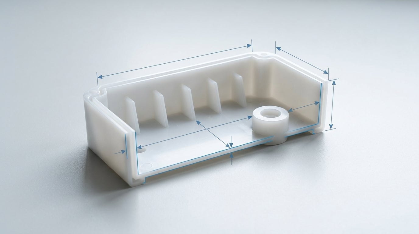
The recommended nominal wall thickness for an injection molded plastic part is roughly 1.0 to 4.0 mm, with most production parts landing between 1.2 and 3.5 mm. The rules that matter just as much are the ones about consistency: no section should be thinner than 40 to 60 percent of an adjacent wall, ribs should be thinner than the wall they support rather than thicker, and heavy sections should be cored out instead of left solid. Get those four right and most sink, warp and short-shot problems never appear.
Wall thickness is the single decision that drives material cost, cycle time, cosmetic quality and whether the tool can fill the part at all. The wall thickness rules for plastic part design set out below cover how that number gets chosen, how ribs and bosses are sized against it, and how to check the result before anyone cuts steel. Change it after the steel is cut and you are paying for new inserts or a new tool, so it is worth getting right at the CAD stage.
Table of Contents
- Wall Thickness Rules for Plastic Part Design: Quick Reference
- What Determines Plastic Part Wall Thickness?
- What Is the Standard Wall Thickness for Common Plastics?
- How Do You Calculate Wall Thickness for a Plastic Part?
- What Are the Rules for Ribs, Bosses, and Reinforcing Features?
- How Do You Avoid Sink Marks and Warpage From Uneven Walls?
- What Are the Most Common Wall Thickness Mistakes?
- How Do You Validate the Final Wall Thickness?
- Frequently Asked Questions
- What is the minimum wall thickness for a molded plastic part?
- Is there one standard wall thickness for all plastic materials?
- Should ribs be the same thickness as the main wall?
- What is the difference between nominal and minimum wall thickness?
- Does increasing plastic wall thickness make a part stronger?
- How do you prevent wall thickness from causing sink marks or warpage?
- Conclusion
Wall Thickness Rules for Plastic Part Design: Quick Reference
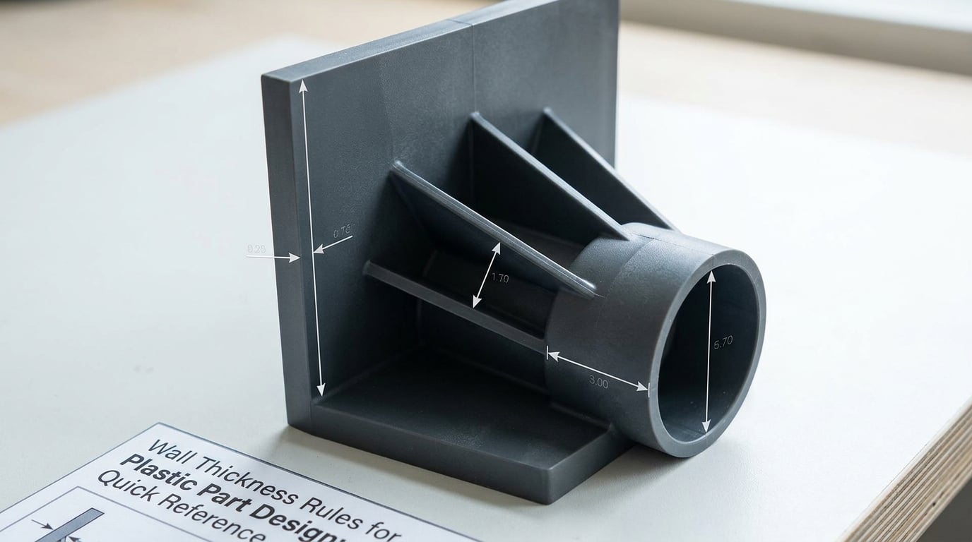
Wall thickness rules for plastic part design, in one table
Here is the short version. Every figure below is a starting point for a typical part, not a substitute for your moulder’s own capability data.
| Design element | Rule | Typical value |
|---|---|---|
| Nominal wall | Target range for most moulded parts | 1.0 to 4.0 mm (0.04 to 0.16 in) |
| Most common design band | Where the majority of parts sit | 1.2 to 3.5 mm (0.05 to 0.14 in) |
| Uniformity | No wall thinner than a set fraction of the wall it meets | 40 to 60 percent of the adjacent wall |
| Rib thickness | Always thinner than the wall it stiffens | 50 to 60 percent of nominal wall, 40 to 70 percent as a workable range |
| Rib height | Ceiling before the rib stops paying for itself | 2.5 to 3 times nominal wall thickness |
| Rib spacing | Clear gap between adjacent ribs | 2 times wall thickness or more |
| Rib root radius | Radius where rib meets wall | 0.25 to 0.5 times wall thickness, up to 1 times on heavily loaded ribs |
| Boss | Outer diameter relative to the hole it holds | Outer diameter at or below 2 times the inner diameter |
| Internal corner radius | Radius on inside corners | 0.25 to 0.5 times the adjacent wall thickness |
| Draft angle | Taper on surfaces parallel to the pull direction | 1 to 2 degrees recommended, 0.5 degrees as an absolute floor |
| Textured surface | Added draft for texture depth | Add about 1 degree per 0.025 mm of texture depth |
| Heavy section | Solid block of plastic | Core it out to a uniform skin, then add ribs to recover stiffness |
Sources disagree on the rib ratio. Some moulders work to 40 to 60 percent, others quote 50 to 70 percent, and both are defensible. The honest position: 50 to 60 percent is where most tooling runs comfortably, and anything above 70 percent starts behaving like a thickening that sinks.
What Determines Plastic Part Wall Thickness?
Wall thickness is not a style choice. It is the output of a handful of engineering inputs, and if you cannot name the input driving your number, the number is a guess.
Material stiffness. Stiffness scales with the cube of thickness for a flat section, so a stiffer resin lets you run a thinner wall for the same deflection. This is the cheapest lever you have: changing grade often beats changing geometry.
Reinforcement. Glass fibre raises stiffness and heat deflection temperature substantially, but it shrinks less and less predictably in the flow direction. Filled parts need slightly higher minimum walls than unfilled ones and much more attention to fibre orientation.
Load direction. A wall loaded in tension or bending carries far more than one loaded in compression. Compressive-only panels can be thinner than a mounting flange carrying a fastener.
Unsupported span. A 1.5 mm wall spanning 20 mm and the same wall spanning 60 mm are different parts. Span-to-thickness ratio drives deflection far more than the material choice does.
Temperature and creep. Every thermoplastic stiffens when cold and softens when hot. A part that must hold a clamp force at 80 degrees needs more thickness than the same part at room temperature, and the design has to survive the creep that comes with sustained load.
Impact and abuse. Drop, vibration and assembly knocks set a minimum. If the part gets hit, a thin wall fails at the first internal corner, which is why root radii matter as much as thickness.
Process. The moulding process caps how thin you can go. Hot runner, high pack pressure, vacuum assist and thin-wall packaging technology all push the floor lower, at a cost in tooling complexity and process control.
What Is the Standard Wall Thickness for Common Plastics?
There is no single standard. What exists is a set of ranges that resin suppliers and moulders agree on as a starting point, and they vary enough that you should treat the numbers below as a first guess and the supplier datasheet as the answer.
| Material | Minimum | Typical nominal | Upper practical limit |
|---|---|---|---|
| ABS | 1.0 mm (0.04 in) | 1.5 to 2.5 mm (0.06 to 0.10 in) | 3.5 mm (0.14 in) |
| ABS/PC alloy | 1.0 mm (0.04 in) | 1.5 to 2.5 mm (0.06 to 0.10 in) | 3.5 mm (0.14 in) |
| Polycarbonate (PC) | 1.0 mm (0.04 in) | 1.5 to 2.5 mm (0.06 to 0.10 in) | 3.5 mm (0.14 in) |
| Nylon PA6 / PA66 unfilled | 1.0 mm (0.04 in) | 1.5 to 3.0 mm (0.06 to 0.12 in) | 4.0 mm (0.16 in) |
| Glass-filled nylon (PA6-GF / PA66-GF) | 1.5 mm (0.06 in) | 2.0 to 3.0 mm (0.08 to 0.12 in) | 4.0 mm (0.16 in) |
| Polyoxymethylene (POM / acetal) | 1.2 mm (0.05 in) | 1.5 to 3.0 mm (0.06 to 0.12 in) | 4.0 mm (0.16 in) |
| Polypropylene (PP) | 1.0 mm (0.04 in) | 1.5 to 3.0 mm (0.06 to 0.12 in) | 4.0 mm (0.16 in) |
| Polyethylene (HDPE / LDPE) | 1.2 mm (0.05 in) | 1.5 to 3.0 mm (0.06 to 0.12 in) | 4.0 mm (0.16 in) |
| Rigid PVC | 1.5 mm (0.06 in) | 2.0 to 3.5 mm (0.08 to 0.14 in) | 5.0 mm (0.20 in) |
| PET / PETG (bottles, thin trays) | 0.6 mm (0.02 in) | 0.8 to 2.0 mm (0.03 to 0.08 in) | 3.0 mm (0.12 in) |
| Polyphenylene ether blend (PPS, PPE) | 1.2 mm (0.05 in) | 2.0 to 3.0 mm (0.08 to 0.12 in) | 4.0 mm (0.16 in) |
| PEEK | 1.5 mm (0.06 in) | 2.0 to 4.0 mm (0.08 to 0.16 in) | 5.0 mm (0.20 in) |
Two cautions on using this table. First, the minimum is a fill limit, not a strength limit; below it the flow front splits and you get a short shot. Second, the upper limit exists because a wall much past 3.5 to 4.0 mm cools slowly, packs unevenly and starts to sink and warp.
Glass-filled grades deserve their own note. Fibre raises stiffness and shrinks total volume by a smaller amount than the unfilled resin, but it shrinks unevenly across the part, so thick filled sections warp readily. Keep filled walls closer to 2 to 3 mm, keep the geometry even, and expect to control the cooling rather than fight it with thickness.
How Do You Calculate Wall Thickness for a Plastic Part?
You rarely calculate a wall from first principles alone. The practical method takes six steps, and the moulder’s guidelines and trial runs close the loop.
Step 1. Define the load and the deflection limit. Write down the force, where it acts, and how much movement you can tolerate in millimetres. “It must not visibly flex” is not a specification.
Step 2. Pick the material and get the real property data. Use the supplier’s flexural modulus for the specific grade at the service temperature, not a generic handbook value. The difference between grades is often the difference between a 1.5 mm and a 3 mm wall.
Step 3. Identify the unsupported span. Measure the longest section of wall with nothing behind it. This is the span that governs deflection.
Step 4. Set the thickness from span, then check it against resin flow. Span-to-thickness ratio is the practical shortcut: long thin parts are hard to fill, and the flow length to wall thickness aspect ratio is what determines whether the melt arrives before it freezes. Short flows can run thinner; long flows need thicker walls, a hot runner, or a gate near the far end.
Step 5. Apply a safety factor and then add ribs rather than thickness. Keep the wall uniform at the chosen value and reach the required stiffness with rib count and rib height.
Step 6. Validate. A trial shot or a structural test on a small sample is the cheapest way to find out you were wrong. Modelling catches geometry, not resin behaviour.
A worked example
Say you have a 300 mm long electronics housing in ABS, unsupported across its width, with a 0.3 mm deflection budget under a light pressing load at 60 degrees. The unfilled ABS rule of thumb puts you near a 2.0 mm nominal wall for that span and temperature. At 2.0 mm, ribs at 50 to 60 percent come out around 1.0 to 1.2 mm, spaced 4 mm or more apart, and no thicker than about 5 to 6 mm tall.
If the housing is glass-filled nylon instead, you move the wall to roughly 2.5 to 3.0 mm to capture the added stiffness, which lets you reduce rib count. The rib and boss ratios still hold. That is the practical value of the stiffness exponent: geometry choices and material choice trade against each other, and you should pick the pair that meets the deflection budget with the least material and the fewest processing risks.
What Are the Rules for Ribs, Bosses, and Reinforcing Features?
Ribs should be thinner than the wall they stiffen. A rib that is the same thickness as the wall, or thicker, behaves as a local thick section, so it sinks, prints a visible line on the opposite surface, and adds cycle time for nothing.
- Rib thickness: 50 to 60 percent of the nominal wall, with 40 to 70 percent a commonly accepted range.
- Rib height: no more than 2.5 to 3 times the nominal wall. Past that you are adding mass and cooling time without meaningful stiffness.
- Rib spacing: 2 times the wall thickness or more between adjacent ribs. Cross ribs are the exception and should be avoided, since intersecting ribs create a thick node that sinks.
- Root radius: 0.25 to 0.5 times the wall thickness, going up to 1 times on ribs that carry real load. A sharp root is a crack starter and a stress riser.
- Rib draft: 0.5 to 1 degree per side, so the rib releases from the core cleanly.
Bosses follow the same logic. Keep the outer diameter at or below 2 times the inner diameter, hold the boss wall at the same 40 to 60 percent ratio to the adjacent wall, tie it into the wall with a gusset rather than a bare fillet, and fillet the base. A tall thin boss is fine; a short fat one is a sink mark waiting to happen.
The stiffness rule behind all of this is worth remembering: adding 10 percent to wall thickness delivers roughly 33 percent more stiffness, because bending stiffness scales with thickness cubed. Ribs deliver the same stiffness with a fraction of the material, and they do it without changing the cooling behaviour of the part. That is why experienced designers reach for a rib pattern long before they reach for a thicker wall.
One caution from practice: ribs are not free. Every rib is another feature the tool has to machine, cool and eject. On a cosmetic surface, put the pattern on the inside, where a sink shows up as a bump on a hidden face rather than a dent in the light.
How Do You Avoid Sink Marks and Warpage From Uneven Walls?
Molten plastic cools from the outside in. A thick section holds heat longer, keeps shrinking longer, and pulls the surface around it inward as it does, which is exactly what a sink mark is. A part warps when different areas cool and shrink at different rates, and unequal thickness guarantees those rates differ.
Four strategies exist, and they are worth ranking deliberately. A uniform wall throughout is the best outcome. A cored section, where a solid block is hollowed to a skin matching the surrounding wall and the lost stiffness is restored with ribs, is nearly as good and often the only option in a thick hub. A tapered transition, where thickness changes gradually over a long blend, is acceptable. An asymmetric wall, where one side is deliberately thicker for flow or stiffness reasons, needs extra cooling and pack control and should be a conscious decision rather than an accident.
| Defect | What it looks like | The thickness mistake behind it |
|---|---|---|
| Sink mark | Visible depression opposite a local bulge | Rib, boss or wall thicker than 60 percent of the adjacent wall |
| Warpage | Part twists or bows after ejection | Uneven wall distribution, unbalanced cooling, fibre orientation |
| Short shot | Part fills only part way | Wall below the resin fill limit, or flow length too long for the wall |
| Voids and trapped air | Bubbles or internal air pockets | Solid mass with no path for air to escape; coring solves it |
| Weld lines | Weak, visible seam where flows meet | Gate placed so two fronts meet on a highly loaded section |
| Cracking at corners | Split at an internal corner | No root radius, or a sharp thickness step |
| Flashing | Thin material at the parting line | Parting line across an area that varies in thickness |
| Ejection drag marks | Whitening or scuffing on a draw-direction face | Draft too shallow, or a surface that is too large and too hot |
Cooling design matters as much as the wall itself. Uniform, balanced cooling circuits placed to follow the geometry, a gate positioned so the melt travels in one direction, a parting line that does not sit across a thickness step, and pack pressure set to fill the section without over-packing it all reduce the visible consequences of the thickness choices you made.
What Are the Most Common Wall Thickness Mistakes?
Six wall thickness rules for plastic part design that get broken most often
1. Borrowing a number from somewhere else. A 3 mm wall from a datasheet means nothing without the grade, the span and the temperature. Work from your own constraints.
2. Making everything the same thick. Uniformity is about consistency, not about the same number everywhere. A housing whose walls are all 3 mm and a hub that is 3 mm is fine; a housing with 1.5 mm walls and a 5 mm hub is a sink mark with a product code.
3. Too many ribs. Ribs closer than 2 times the wall thickness act as a thick slab rather than as separate stiffeners, and they extend cooling time.
4. Sharp transitions and sharp corners. A sudden step in wall thickness concentrates stress and gives shrinkage nowhere to go. Blend it and put a radius on it.
5. Designing solid and coring later. This is the most common expensive mistake, because it usually surfaces as a quotation conversation rather than a design conversation. Decide what gets cored while you are still in CAD.
6. Ignoring the tool and the shrinkage rate. A 0.5 percent versus a 2 percent shrinkage difference changes every dimension on the drawing, and cavities sized for solid geometry will produce an undersized cored part with unexpected draft problems.
There is a seventh worth naming for anyone moving from prototypes: a part designed to additive manufacturing rules can end up 3 mm solid with no draft, no ribs and no fillets, because that is exactly what a printer likes. Production tooling will not.
How Do You Validate the Final Wall Thickness?
Before anyone cuts steel, run the drawing through this list. It takes fifteen minutes and it maps directly to the failures that come back as rework.
- Material grade specified by name, with the supplier’s data sheet referenced
- Shrinkage rate applied to every dimension, including cored sections
- Draft at 1 degree or more on all draw-direction faces, 0.5 degrees absolute floor
- Root radii of 0.25 to 0.5 times the wall on every internal corner
- No section thinner than 40 to 60 percent of an adjacent wall
- Ribs at 50 to 60 percent of nominal wall, height 3 times or less, spacing 2 times wall or more
- Boss outer diameter at or below 2 times the inner diameter, gusseted to the wall
- Heavy sections cored, with the cored skin matching the surrounding wall
- Fibre orientation considered and not fighting the parting line on filled parts
- Sink-visible surfaces identified, and the thickness feature opposite them checked
- Tolerances set for the material, with tight tolerances on stable, well-supported features only
- Fill and cycle time estimated against the cavity, not guessed
- Inspection criteria defined for anything the drawing alone cannot hold
- First-article measurement plan agreed before the first shot
Then validate physically. A short-run trial or a single-cavity test tool will show you sink, warp, fill and cycle time in a fraction of the time it takes to fix any of them later. If the thickness has to change after that point, the change is measured in insert modifications, not in a drawing update.
Frequently Asked Questions
What is the minimum wall thickness for a molded plastic part?
For most thermoplastics the practical minimum is 1.0 mm (0.04 in), rising to 1.5 mm (0.06 in) for glass-filled nylons, rigid PVC and PEEK, and dropping to 0.6 mm (0.02 in) for PET in thin-wall packaging. That floor is a fill limit rather than a strength limit: below it, the flow front splits and you get a short shot. Moulders quote their own minimum based on resin flow, flow length and tooling, so treat the table as a starting point and confirm it with them.
Is there one standard wall thickness for all plastic materials?
No. Nominal wall thickness typically falls between 1.0 and 4.0 mm across molded parts, but the useful figure depends entirely on resin, grade, span and load. A glass-filled nylon housing often runs 2.5 to 3.0 mm where an unfilled ABS cover of the same size runs 1.5 to 2.5 mm. The only real standard is that the supplier and the moulder decide, so pull the number from the grade-specific data sheet rather than a generic guide.
Should ribs be the same thickness as the main wall?
No, they should be thinner. The usual rule is 50 to 60 percent of the nominal wall thickness, with 40 to 70 percent an accepted range, and rib height capped at 2.5 to 3 times the wall. A rib as thick as the wall becomes a local thick section, which sinks, prints a visible mark on the opposite surface and lengthens cycle time while adding no meaningful stiffness.
What is the difference between nominal and minimum wall thickness?
Nominal wall thickness is the design target for the main wall, and every rib and boss ratio is measured against it. Minimum wall thickness is the thinnest section the process can reliably produce and fill, which depends on resin flow, flow length and the equipment. Your nominal value should sit well above the minimum, and no local feature should drop anywhere near it.
Does increasing plastic wall thickness make a part stronger?
It makes a part stiffer, not simply stronger. Bending stiffness scales with thickness cubed, so a 10 percent increase in thickness delivers roughly 33 percent more stiffness. Strength and impact resistance behave differently, and a thicker wall can sink, warp and cool more slowly. In most designs, a thinner uniform wall with well-proportioned ribs beats a thick wall on every measure except raw section size.
How do you prevent wall thickness from causing sink marks or warpage?
Keep sections uniform so cooling rates match, core out any heavy region to a skin matching the surrounding wall, and keep ribs and bosses at 50 to 60 percent of the wall they attach to. Then control the process: balance the cooling circuits, place the gate so the melt travels in one direction, keep the parting line off thickness steps, and set pack pressure to fill the section without over-packing. Uneven thickness and uneven cooling are what create the defects.
Conclusion
Start by fixing three things: the material grade, the load and deflection limit, and the manufacturing process you are committing to. Once those are written down, most of the wall thickness rules for plastic part design take care of themselves: the thickness follows from the supplier’s data and the moulder’s capability rather than from a number borrowed from another drawing, and a trial run confirms it before anyone cuts steel.