
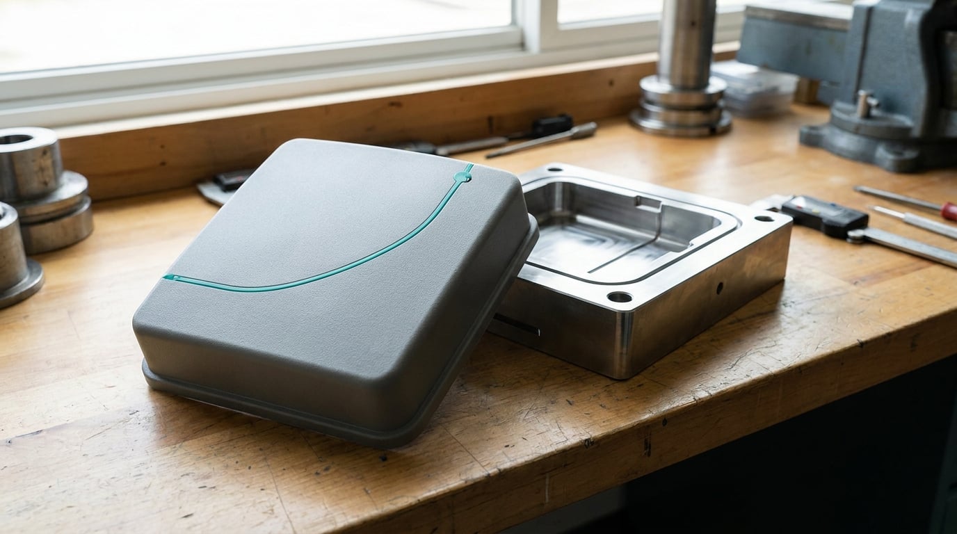
Gate placement mistakes to avoid in injection molding start with one fact: the gate is the only opening in the cavity, and everything downstream is a consequence of where you put it. Fill pattern, weld line location, air traps, sink marks, the visible gate vestige, and the direction of molecular grain all trace back to that single decision. Unlike wall thickness or draft, you cannot rework it with a process tweak once steel is cut.
That is why gate location is normally locked during part design and reviewed at the DFM meeting, not settled by the mold shop after the CAD file lands. If you own the geometry, you own the gate.
Two terms come up constantly here, so define them once. Gate placement is the choice of where molten plastic enters the cavity. A gate vestige, also called a witness mark or gate mark, is the small disc of plastic left where that entry point was cut away. Every mistake below traces back to one of those two ideas.
Table of Contents
- Gate Placement Mistakes to Avoid in Injection Molding at a Glance
- 1. Placing the Gate in a High-Stress or Unsupported Area
- 2. Creating a Weld Line in a Visible or Weak Area
- 3. Directing Resin Into a Drip or Air Trap
- 4. Ignoring Air Venting at the End of Flow
- 5. Placing the Gate Where the Mark Is Cosmetically Unacceptable
- 6. Forcing Melt Around Threads, Inserts, or Metal Features
- 7. Creating Uneven Wall Thickness and Flow Direction
- 8. Allowing the Gate to Make Sharp or Brittle Features
- 9. Making the Gate Difficult to Degate or Trim
- 10. Selecting a Convenient Location Without Considering the Whole Tool
- Frequently Asked Questions
- What is a gate vestige in injection molding?
- What are the common causes of weld line defects in injection molding?
- How do you reduce weld lines in injection molding?
- What causes air bubbles and voids in molded parts?
- What are the typical rules for gate placement?
- Does gate placement affect part strength?
- Conclusion: Validate the Gate Location Before Tooling
Gate Placement Mistakes to Avoid in Injection Molding at a Glance
The table below maps each mistake to the defect it creates, where that defect shows up on the part, and the correction. Skim it first, then read the section for the failure you recognize.
| Mistake | Defect created | Where it shows up | Correction |
|---|---|---|---|
| Gating a thin unsupported wall or sharp corner | Stress concentration, cracking, fill hesitation | Corner, rib root, snap beam | Relocate the gate to a thick section, add local support |
| Weld line landing where load concentrates | Weak seam, premature failure | Around a hole, boss, or cutout | Shift the flow so the seam moves off the load path |
| Aimless melt path into a drip or blind pocket | Air entrapment, burn marks, short shot | Deep rib, cored pocket, text or logo | Re-aim the flow, overcore the pocket, vent the endpoint |
| No vent opposite the end of flow | Short shot, flow marks, hesitation | Last corner to fill | Add a vent at the final fill point, or move the gate |
| Gate on a class A cosmetic surface | Gate vestige, witness mark, blush | Any painted, polished, or seen surface | Move the gate, use a hot tip, add a flush dimple |
| Melt driven hard around an insert or thread | Jetting, insert marking, erosion | Metal insert, threaded boss | Gate closer to the feature, slow the entry, enlarge the gate |
| Single gate on a thick section or round part | Sink marks, warpage, differential shrinkage | Thick areas, flat panels, discs | Balance the flow with multiple gates, equalize wall thickness |
| Gate forcing a sharp turn into a thin feature | Brittle features, cracking at the root | Living hinge, snap fit, tab | Align flow with the feature, add radius at the root |
| Gate buried where it cannot be trimmed | Tool damage during degating, rework | Deep recess, internal rib | Plan access for the trim die and the ejector layout |
| Gate chosen from the CAD view alone | All of the above, discovered after tooling | Whole part | Run fill analysis, review cooling, ejection, and footprint |
1. Placing the Gate in a High-Stress or Unsupported Area
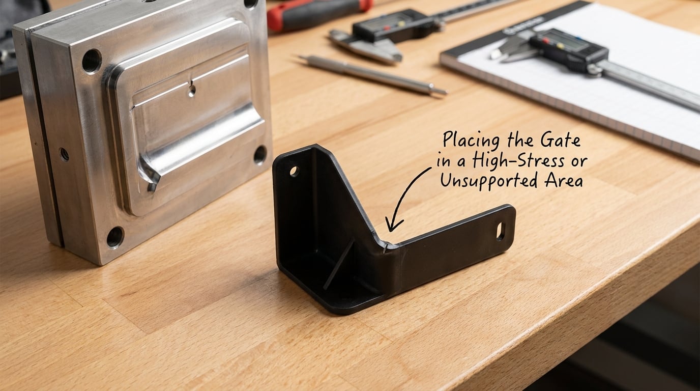
The most expensive gate mistake is putting the entry point where the part is already fragile. A gate that terminates next to a sharp corner, a thin unsupported wall, or the root of a snap beam concentrates both the flow front and the packing force into the smallest cross-section on the part.
Resin arriving at a thin section has nowhere to go, so the pressure spike shows up as a local stress riser. In a snap-fit arm, that riser becomes a crack at the root. In a thin web, it becomes a hesitation mark or a short.
The fix is unglamorous: gate the thickest section you can reach and let the flow travel. If the gate must sit near the corner, add a local radius or a small supporting rib so the section is not carrying the load on its own.
2. Creating a Weld Line in a Visible or Weak Area
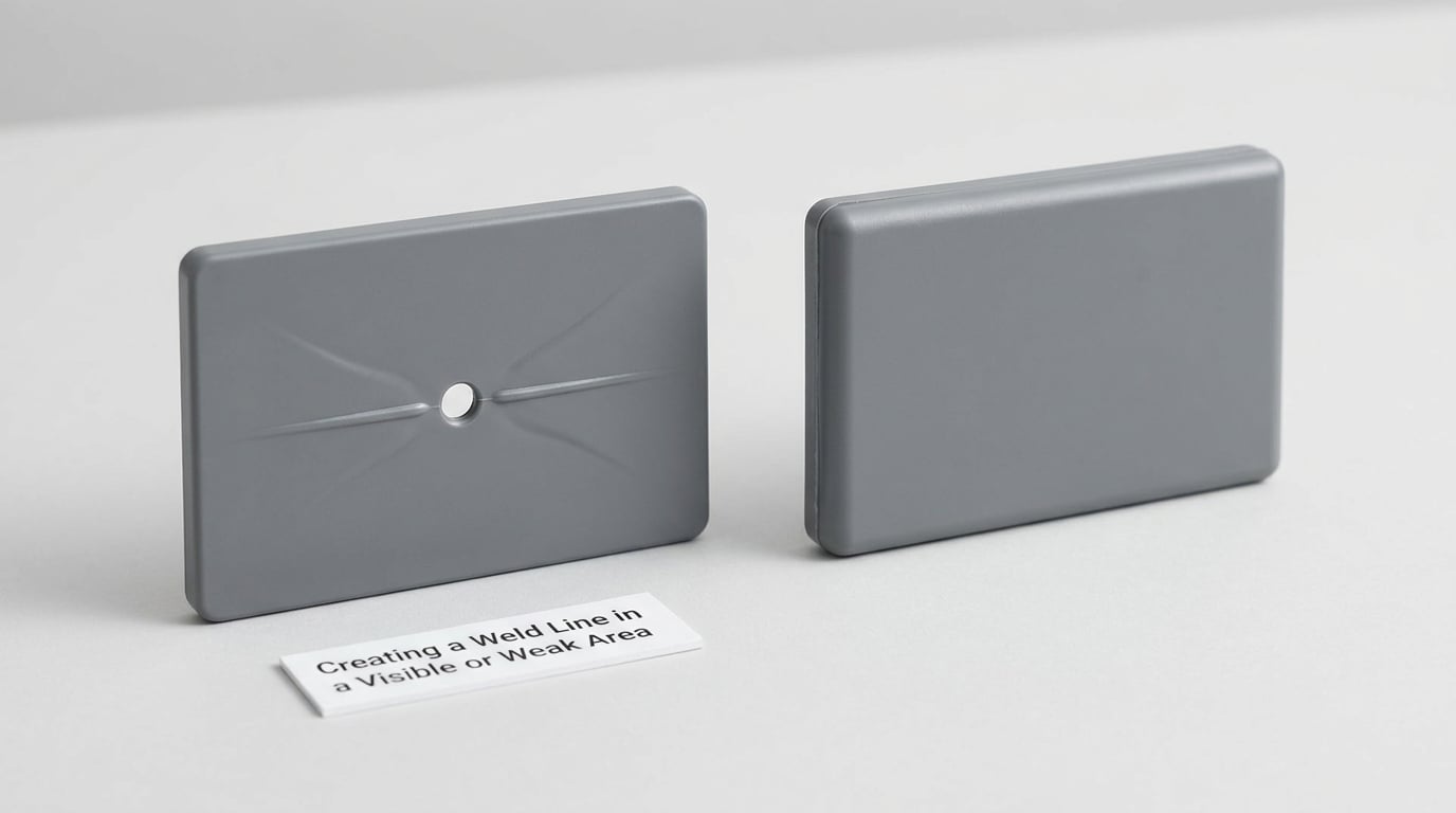
A weld line forms wherever two flow fronts meet after splitting around a hole, a boss, or a cutout, or where melt arrives from two separate gates. The two fronts fuse without fully mixing, and the seam is weaker and often more visible than the surrounding surface.
Most people use the wrong word. A weld line is two melt fronts meeting; a knit line is a partial fusion at a flow front that was diverted and rejoined within a single front. Both behave the same way for design purposes, so treat them as one problem.
Gate position moves the seam. Gate a round plate from one side and the split around a center hole lands at a predictable spot. Shift the gate, change the split geometry, or gate the feature directly so the seam runs where nobody can see it and nothing loads it.
3. Directing Resin Into a Drip or Air Trap
Melt does not flow uphill politely, and it does not fill a blind pocket evenly. When the gate aims into a deep rib, a cored pocket, or raised text, the flow front arrives at a surface it has to climb over, and the air already in that pocket gets compressed rather than displaced.
The symptoms read differently depending on how compressed it gets. Mild entrapment gives splay or a faint silvery streak. Severe entrapment gives burn marks, voids, or a hesitation line where the melt stalled waiting for pressure to build.
Three fixes work: re-aim the flow so it sweeps along the pocket instead of into it, overcore the pocket so the surface is a gentler slope the melt can climb, or move the gate so the pocket fills from the open side. Fix the geometry, not the machine.
4. Ignoring Air Venting at the End of Flow
The last place the cavity fills is the place that needs an escape route. Air sits at the end of flow, ahead of the advancing melt, and it has to leave through a vent or it compresses until the melt stops.
Gate location and vent location are a single decision, and pairing them is where most tools go wrong. Place the gate at one end of a long thin panel and you have also decided the end that needs venting, which is the far end, the corner nobody looks at.
Vents that are too small or too late produce hesitation marks, short shots at the last corner, and flash when the vent finally blows. Size the vent for the material and put it at the true end of fill. If the geometry will not allow a vent, move the gate so the end of flow lands somewhere accessible.
5. Placing the Gate Where the Mark Is Cosmetically Unacceptable
A gate vestige is unavoidable on a cold-runner tool. Someone cut it off, and the toolmaker either dressed it flush or planned for it. That little disc sits exactly where your eye goes first on a shiny, painted, or class A part.
The numbers people publish for a hot tip give you a sense of the target: a vestige roughly 0.060 to 0.080 inch across and 0.010 to 0.020 inch proud of the surface, trimmed flush to about 0.005 inch. On a black textured enclosure that is invisible. On a chrome bezel it is a defect report.
Two options remove the problem. Gate on a hidden surface, such as an internal wall or the inside of a flange. Or add a small dimple at the gate location so the trimmed vestige sits at the bottom of a recess rather than proud of the face. On painted or textured parts the dimple reads as a design feature.
6. Forcing Melt Around Threads, Inserts, or Metal Features
Metal inserts do not melt. When the gate is set far enough away that the flow front has to wrap around an insert boss and turn sharply, the melt accelerates into that turn, and you get jetting, a hard stream of material aimed directly at the insert face.
Jetting is a gate-geometry problem wearing a process problem’s clothes. Raising or lowering melt temperature and adjusting the fill speed will change how bad it looks without fixing why the stream formed. Erosion of the insert face, incomplete filling behind the insert, and stress in the surrounding plastic all follow the same root.
Bring the gate closer so the fill arrives at the insert as a broad front rather than a narrow jet, and give the gate enough diameter that the material is not being forced through a small opening at high shear. Gear applications hit this constantly, and a perimeter tab gate is often the wrong answer where a pin or tunnel gate placed at the hub works far better.
7. Creating Uneven Wall Thickness and Flow Direction
Gating a thick section is the classic beginner error. The gate says to the melt, fill the thick part first, because that is where the volume is. The thick part then cools slower, shrinks more, and pulls a visible sink into the surface a few millimeters away.
On a long flat panel gated at one corner, the same imbalance shows up as warpage. Differential shrinkage across the part is not equal to a uniform shrinkage, and the tool was cut on a nominal value, so the distortion is yours to live with.
The second half of this mistake is flow direction. Gating a wall from the side creates a rib at the entry that freezes orientation one way and leaves the rest of the wall packed another way. Keep walls within a consistent thickness ratio, gate to the thickest section that will not show, and use multiple gates on circular or symmetric parts so the shrink is balanced around the center.
8. Allowing the Gate to Make Sharp or Brittle Features
A living hinge, a snap-fit arm, and a thin tab all depend on material flow staying predictable. When the gate aims into a sharp turn to reach them, the flow front stretches, and the molecules freeze in an orientation that does not match the load.
The result is a feature that passes the first cycle test and fails at cycle 400,000. Cracking starts at the root where the flow direction changed, not at the point of maximum applied stress.
Align the flow with the feature rather than across it, keep the entry angle gentle, and put a generous radius at the root. Where the geometry will not allow a straight path, split the flow early with a second gate and let the fronts meet somewhere that is not in service.
9. Making the Gate Difficult to Degate or Trim
The vestige has to be removed, and the removal method has to be decided at the same time as the gate location. A vestige sitting in a deep recess, facing a wall, or buried under a rib may not be reachable by the trim die or the degating setup at all.
Gate geometry also fights the ejector layout. If the gate pushes the part onto the core side harder than the ejector pins can release, the part stays put, the operator compensates by shortening the metering stroke, and the fill problem gets worse. That loop is a geometry problem dressed up as a machine setting problem, and it is common on the floor because the machine settings are the only knobs most operators can turn.
Plan the whole removal story: where the trim die or the hot-cut tool reaches, which side of the mold the gate sits on, and how the part releases. Pin gates typically sit on the non-cosmetic side, which is a real advantage for degating. Confirm it before the steel is cut.
10. Selecting a Convenient Location Without Considering the Whole Tool
Most gate decisions that go wrong started with a CAD screenshot and a short flow path. On screen it looks balanced. The mold has other opinions: cooling, ejection, venting, side actions, machining access, the runner system, and the machine’s maximum part size and platen footprint.
Cooling decides where you can put a gate, because a gate on a hot, poorly cooled section is a sink mark waiting to happen. Runners consume footprint, and the footprint decides the largest part the tool can hold. A gate position that forces a long runner can make the part unbuildable before the filling even starts.
Run a fill analysis before you commit. It is cheap compared with the alternative, which is new steel, new cycles, and a schedule that slipped by weeks. Fixing a wrong gate after tooling commonly lands in the five figures, and the money is only part of it.
Frequently Asked Questions
What is a gate vestige in injection molding?
A gate vestige is the small disc of plastic left at the point where melt entered the cavity, after the runner and gate are cut away. It is also called a witness mark or gate mark. A hot tip leaves roughly 0.060 to 0.080 inch diameter and 0.010 to 0.020 inch proud, trimmed flush to about 0.005 inch. On cosmetic surfaces, gate elsewhere or add a flush dimple.
What are the common causes of weld line defects in injection molding?
Weld lines appear where two flow fronts meet. The usual causes are a split in the flow around a hole, boss, or cutout; two gates filling the same cavity; and a gate positioned directly opposite the split point. Cold mold temperature, low melt temperature, and poor venting make the seam weaker and more visible without being the underlying cause.
How do you reduce weld lines in injection molding?
Relocate the gate so the flow fronts meet away from load paths and away from view. Gate the feature directly when the geometry allows it, or add a second gate so the meeting point moves. Increase melt and mold temperature to improve fusion at the seam, size the gate large enough to avoid freezing the front early, and vent the end of fill so the fronts are not fighting trapped air.
What causes air bubbles and voids in molded parts?
Trapped air ahead of the flow front is the usual cause, and gate placement decides where that air goes. Gates that aim into blind pockets, deep ribs, or cored features compress air instead of displacing it, which shows as splay, burn marks, or voids. Insufficient venting at the end of flow does the same thing. Fix the flow direction and vent the true end of fill.
What are the typical rules for gate placement?
Gate the thickest section that is not cosmetic, keep flow length within roughly 100 to 200 times wall thickness, and balance flow on circular or symmetric parts with more than one gate. Keep weld lines off load paths, match the flow direction to the feature, plan the vent at the end of fill, and confirm the gate can be trimmed before the tool is cut.
Does gate placement affect part strength?
Yes, in two ways. Molecular orientation freezes along the flow direction, so a part loaded across that grain is weaker than one loaded with it. Weld lines form where flow fronts meet, and those seams are weaker and less reliable than the surrounding material. Both effects come from where the melt enters, which is why the gate is a structural decision, not a cosmetic one.
Conclusion: Validate the Gate Location Before Tooling
Start before CAD is released, not after the first shot. Map the fill, the weld line, the air, the stress, the cosmetic surface, the cooling, and the tool access in that order, and the correct gate usually falls out of the constraints rather than out of convenience.
When two gate options survive that list, run the fill analysis and let the pressure and temperature curves decide. Then confirm the gate can be degated, the vent can be placed at the true end of fill, and the runner fits inside the footprint. Gate placement mistakes are cheap to prevent and expensive to fix, and the fix always lands on someone.