
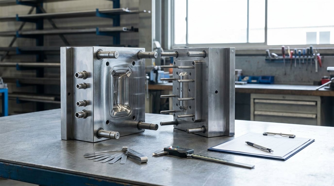
A mold maintenance schedule for injection molding runs on cycles, not calendar days: a visual check and light clean every 5,000 to 20,000 shots, a detailed service with lubrication and fastener checks every 50,000 to 100,000, and a full teardown with dimensional verification every 250,000 to 500,000. Shot-count based maintenance means the interval starts when the mold counter crosses a threshold, not when a date lands on a calendar. Building a usable plan takes an afternoon of record work and an hour to load it into your CMMS or MES. Here is the whole process, in the order I would set it up.
Table of Contents
- What You Need
- Create a Mold Maintenance Schedule for Injection Molding
- Common Mistakes
- Frequently Asked Questions
- How often should an injection mold be cleaned?
- What maintenance is safe for operators to perform between technician visits?
- How do cycle count and calendar time change the maintenance schedule?
- What mold problems require maintenance before the next scheduled interval?
- How often should hot-runner systems and thermocouples be inspected?
- How can a maintenance log help identify recurring mold failures?
- Conclusion
What You Need
You cannot set intervals without knowing what a mold has already survived, so the first hour of this job is paperwork, not greasing. Pull five things together before you write a single task.
A mold register. One row per mold with the mold ID, cavity count, the press or presses it runs on, the steel and insert layout, the shot counter reading at the start of the program, and the date of the last full teardown. A mold without an ID and a counter is a mold you will never schedule correctly.
Machine hours and shot counts. Most presses log cycles automatically; export them monthly. If a counter is manual, put a tallied sheet next to the press and have the operator update it at every mold change.
Historical downtime and defect data. Pull twelve months of work orders and note which molds generate the unplanned stops and which ones produce flash, short shots, or dimensional drift. That record is the strongest argument for a tighter interval, because it turns a generic rule into a mold-specific one.
OEM instructions. The mold builder’s manual sets the minimum for lubrication points, cycle limits, cleaning chemistry, and storage procedure. Anything you build has to sit on top of that document, never replace it.
Current condition and complexity. Note whether the tool has hot runner, sliders, lifters, inserts, or conformal cooling, and whether it runs abrasive resin. Complexity sets how long a service takes and how much can go wrong during it.
Resources and people. Brass picks and brass wire brushes, a plastic-safe cleaning solution, an NSF H1 or food-grade lubricant, a feeler gauge, calipers, a surface plate, an infrared thermometer or contact thermocouple reader, an anti-rust or corrosion-inhibitor film for storage, spare ejector pins, springs, O-rings and heater cartridges matched to the tool, a torque wrench, and a camera. Then name owners: an operator role for shift checks and a technician role for each PM tier, with a named backup for each.
Part prints and process settings. Pull the current drawing for the part each mold makes, plus the validated process sheet with fill, pack, temperature, and cooling targets. A PM is only a success if the mold comes back producing parts inside print, and you cannot verify that without the print in hand. If a tool has been running a superseded revision, fix that before you schedule anything, because a maintenance plan built on the wrong print produces false confidence.
One more piece of information prevents most arguments later: the last time the mold was modified. A new ejector plate, a re-machined cavity, or a resized sprue bushing resets the wear baseline. Most missed failures trace back to work done at the last repair and never re-documented, which is why the modification field belongs in the register from day one.
One safety point belongs here, because no competitor page bothers with it. Before a mold is pulled, opened, or has slides removed, the press goes through lockout/tagout: shut down, isolate energy sources, release stored pressure, and apply personal locks. Hot runner systems, high-pressure hydraulic lines, and heated platens hold enough energy to injure a technician who treats a powered-down press as a safe press. Confirm the tool steel and any inserts have cooled to a handling temperature before hands go near the clamps.
Create a Mold Maintenance Schedule for Injection Molding
A working mold maintenance schedule has four layers that get confused when people try to do this in one document. Shift-level checks belong to the operator and happen continuously. Periodic service belongs to the technician and happens at a shot or calendar interval. Condition-based interventions happen on a signal, not a date, and they override the plan. Annual or major-overhaul work covers preservation, dimensional re-qualification, and long-term integrity. Keep the four layers separate and each one stays easy to audit.
1. Establish the Baseline and Maintenance Triggers
Baseline the tool before you schedule it, or every interval you set is a guess. With the mold open and cool, record the cavity and core condition, the parting line and any flash or wear landmarks, ejector pin diameters at a defined measurement point, slide and gib engagement, sprue bushing condition, vent land depths, and the thickness of any deposit in the cooling lines.
Photograph it. Standardized photos taken from the same four angles at every PM turn a subjective “looks fine” into a trend you can compare, and photographs are the fastest way to see a wear land growing across a year.
Measure the cooling circuit while you are in there: flow rate at the inlet and outlet, the temperature differential across the mold, and the time it takes to reach a stable process temperature. Those three numbers are your reference for every future comparison, and they are what turns cycle-time creep into a diagnosis rather than a mystery.
Then assign a trigger to the mold. A typical trigger is “service due at the next threshold the counter crosses,” and each threshold carries a task list, an estimated duration, a required skill level, and a list of parts to have on the shelf. Molds that run on several presses need one master counter tied to the mold ID, not one counter per machine, otherwise the interval resets every time the tool changes line.
2. Set Daily and Shift-Level Checks
The shift check is short enough to actually get done, which means under two minutes per cavity-side check. It is a look, a listen, and a sample part, in that order.
- Guards and interlocks. Photoelectric eyes, safety gates, and the mold area shield are in place and functional before the first shot.
- Leaks. Check the mold for hydraulic or coolant leakage at fittings, the toggle area, and the hot runner manifold. Oil on the platen floor is a leak you will find after it becomes a safety issue.
- Cooling connections. Hoses are seated, no drips at the quick connects, and inlet and outlet temperatures are steady rather than drifting.
- Parting line and flash. Run a few parts and look for flash forming on one side only, which usually points to a guide pin, gib, or clamping problem rather than resin.
- Vents. Listen for a squeal or a hiss on the last part of the fill. A singing mold is a venting problem and venting problems load the parting line unevenly.
- Ejection. Parts drop cleanly, ejector pins retract fully, and the part is not hanging on one pin or being scraped off the core.
- Part quality. Weight, dimensions, and visual condition checked against the part print or a golden sample, plus a first-article check after any mold change.
Define stop-work criteria in writing, because a verbal one gets ignored at 2 a.m. If a leak is spraying, if the ejector pins are not retracting fully, if flash is cutting the operator’s hand on the parting line, or if parts are landing in the chute inconsistently, the mold comes out and the technician is called.
3. Schedule Weekly and Monthly Care
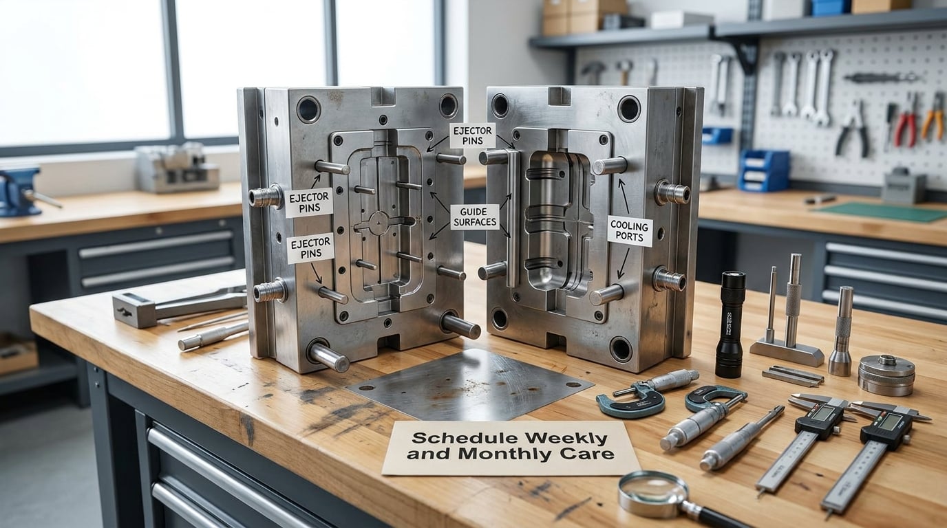
Technician service happens at a shot count and at a time interval, whichever comes first. Use the shot count as the primary trigger and the calendar as a backstop for low-volume tools that never reach the counter.
At every service, expect a 30 to 60 minute task list: open the mold, clean deposits from the cavity, core, and parting line with a brass pick and brass brush rather than steel, clear every vent, clean ejector pin heads, inspect guide pins and bushings, and check the slide and lifter gibs for wear and alignment. Lubricate the points the OEM lists and no others. Over-lubrication is a real failure mode, since excess grease collects debris and gets dragged into the guide surfaces it was meant to protect.
For a four-cavity hot runner tool running three shifts, budget roughly 30 minutes for the low tier, around 90 minutes for the detailed tier, and a full day for the teardown tier, and schedule them in a planned window rather than waiting for a defect to force the stop. Low-volume tools that cycle a few hundred shots a month will never trip a counter threshold, so give them a quarterly calendar service covering cleaning, lubrication, cooling checks, and a storage-preservation step if the tool will sit longer than a month.
When planning the window, count the changeover, not just the service. Pulling a tool, servicing it, re-qualifying it, and running a first article takes considerably longer than the hands-on work, and the schedule is more credible to production when it shows the full time rather than the technician’s time alone.
Monthly, add fastener torque verification on the clamp and tie-bar hardware, ejector return spring inspection, hot runner thermocouple and heater verification against set points, and a cooling circuit flow and temperature check. Quarterly, inspect the sprue bushing for a worn radius, verify parting line flatness against a feeler gauge, and confirm the mold still closes within the expected stack height on the platen.
Annual or at the major-overhaul tier, strip the mold down fully: disassemble the hot runner, replace O-rings and seals, flush every cooling line with a descaling solution appropriate to the resin and the tool steel, replace worn ejector pins, springs, and wear plates, and re-qualify the cavity to the original part print on a surface plate. A clean and lubricated mold that has lost three HRC of hardness or grown a 0.001 inch parting line gap is not healthy, and no amount of cleaning changes that.
4. Add Condition-Based Interventions
Calendar and cycle intervals describe the average mold. The signals below describe yours, and they take priority over the schedule every time.
| Signal you see in the part or the process | What it usually points to | Act when |
|---|---|---|
| Flash appearing mid-run on one side only | Guide pin, bushing, gib or wear plate wear; uneven clamping | Pull and inspect immediately, not at the next interval |
| Short shots in one cavity only | Blocked vent, cold cavity from scale, or a blocked nozzle | Check vents and cooling flow at the next planned stop |
| Cycle time creeping up with no process change | Scale deposit in the cooling circuit reducing heat transfer | Flush the cooling lines; a thick deposit is a large transfer loss |
| Parts sticking in the cavity | Under-polished surface, release agent failure, or ejection imbalance | Inspect the cavity surface and ejector alignment |
| Discoloration or streaks that come and go | Resin degradation, trapped gas, or thermal imbalance in the hot runner | Check heater and thermocouple operation, verify resin drying |
| Dimensions drifting within a lot | Cooling variation, packing pressure drift, or cavity wear | Compare cavity temperature across the tool and re-qualify dimensions |
Resin changes the intervals as much as wear does. Filled and reinforced grades carry abrasive filler that cuts into cavity steel, vents, and ejector pins, and PVC or flame-retardant grades off-gas corrosive vapors that attack unprotected steel. A molded part that looks fine while the mold sits still on the floor is a mold that has been quietly damaged for a week.
5. Set the Mold Maintenance Schedule for Injection Molding Intervals
Now translate the baseline into a usable document. Five tiers cover most molding operations, and each tier needs a shot threshold, a task list, an estimated downtime figure, and an owner.
| Interval (shots) | Tasks | Typical downtime | Owner |
|---|---|---|---|
| Every shift | Leaks, cooling connections, parting line, vents, ejection, part quality | None, in-process | Operator |
| 5,000 to 20,000 | Visual inspection and light clean of cavity, core, vents and parting line | 15 to 30 minutes | Operator or technician |
| 50,000 to 100,000 | Detailed inspection with lubrication, fastener checks, ejector service, cooling flow check | 1 to 2 hours | Technician |
| 250,000 to 500,000 | Full teardown, cooling line flush, seal and O-ring replacement, dimensional verification | 4 to 8 hours | Technician plus quality |
| Annual or per part print revision | Complete strip, hot runner service, re-qualification to print, storage preparation | 1 to 3 days | Tooling engineer |
Adjust the thresholds by resin. Unfilled thermoplastics run at the published intervals; glass or mineral filled grades, flame-retardant ABS, and PVC cut the interval substantially because the filler wears vents and cavity steel and the additives attack surfaces. High-temperature engineering resins, medical and food-grade tooling, and hot runner molds tighten further, since the cost of a bad part is higher than the cost of an extra PM window.
Load the triggers into the system that already runs the press. In an MES or CMMS, key each work order to the mold ID, set the trigger on the mold shot counter, define a due window, and require a technician sign-off before the counter resets. In a spreadsheet, the same logic works with a counter column, a next-due column, and a formula that compares them.
Keep mold PM separate from machine PM in the same documents. Machine PM covers hydraulic oil, filters, screw and barrel checks, tie-bar lubrication, and electrical checks. Mold PM covers the tool. A team that does one and assumes it did both is the most common gap on the floor, and it is the one that produces an expensive surprise at the 200,000th shot.
6. Record Work and Close the Loop

The log is the part of the schedule that pays for itself. Without it you cannot tell whether a mold failed early because of a missed interval or because of a design issue, and you will write the same schedule for every tool on the floor for years.
A usable entry carries: date and mold ID, shot count at service, cycle time at start and end, the tier performed, the technician, tasks completed, parts replaced, measurements and readings, anomalies found, corrective action taken, downtime minutes, first-article result after the service, and sign-off. Add a photo field and a wear measurement field, because a number entered consistently at each PM is the only way to project a replacement date with any confidence.
| Field | Example entry |
|---|---|
| Date and mold ID | 2026-03-11, M-204 (4-cavity, hot runner) |
| Shot count at service | 98,410 |
| Cycle time start / end | 31.2 s / 29.8 s |
| Tier performed | Detailed inspection, 50k to 100k |
| Measurements | Cooling delta 9.4 C, ejector pin wear within limit, parting line gap within limit |
| Anomalies | Vent 3 partially blocked, ejector pin 7 return spring fatigued |
| Corrective action | Vent cleared, spring replaced, cooling circuit flushed |
| Downtime and sign-off | 95 minutes, technician initials, quality first-article pass |
Review the log monthly and look for repeats. Three entries with the same vent on the same cavity is a mold design or resin problem, not a maintenance problem, and it belongs on the tooling engineer’s desk rather than in the PM tier. Track unplanned downtime percentage, scrap rate, first-pass yield after PM, and cycle time trend per mold; those four numbers tell you whether the schedule is actually working.
Common Mistakes
- Calendar-only scheduling. A tool that runs 200 shots a month and a tool that runs 2 million shots a year are both told to be serviced on the same date. Fix: trigger on the mold shot counter, use the calendar only as a backstop for low-volume tools.
- Skipping the cheap intervals. Technicians treat a 20-minute light clean as trivial and skip it, then meet a parting line failure that costs far more. Fix: make the low tiers mandatory and logged, with the downtime estimate published next to the tasks.
- Wrong lubricant or too much of it. A general-purpose grease in a medical or food contact mold, or a heavy coat on a guide surface, collects debris and wears the bushing faster. Fix: use the lubricant specified by the mold builder, in the quantity specified.
- Cleaning with the wrong tool or chemistry. Steel picks scratch cavity steel, and a harsh solvent attacks some mold coatings. Fix: brass picks and brass brushes, a plastic-safe cleaner, and a quick test on a hidden surface.
- No first-article check after service. A technician closes the mold and puts it straight back into production. Fix: run and measure a first article against the part print before releasing the tool to the line.
- Repairs that never make it into the log. Emergency fixes happen, nobody records them, and the same failure repeats. Fix: no sign-off, no release to production.
- Ignoring the OEM manual. A generic schedule overrides the builder’s specified cycles, chemistry, and storage procedure. Fix: the OEM document is the floor, and your schedule only adds intervals and conditions on top of it.
- Opening a mold on a live press. Slides and parting surfaces get handled near stored energy and hot platens. Fix: lockout/tagout, depressurize, and cool before the mold is touched.
Frequently Asked Questions
How often should an injection mold be cleaned?
Most shops run a visual check and light clean every 5,000 to 20,000 shots, a detailed clean with lubrication and fastener checks every 50,000 to 100,000 shots, and a full teardown with cooling line flush every 250,000 to 500,000 shots. Abrasive and filled resins shorten those intervals. If the mold is idle for more than a week, clean and apply corrosion protection before it goes into storage.
What maintenance is safe for operators to perform between technician visits?
Operators should handle anything visual and reversible: checking guards and interlocks, looking for hydraulic or coolant leaks, confirming cooling hoses are seated, running sample parts to check flash, venting noise, ejection, and part dimensions, and confirming the mold closes cleanly. Anything requiring a mold to be opened, a slide pulled, or a tool touched belongs to a trained technician with lockout/tagout applied.
How do cycle count and calendar time change the maintenance schedule?
Cycle count is the primary trigger because wear tracks shots, not days. Calendar time matters for molds that rarely run, for storage and preservation checks, and as a backstop so an idle tool is still inspected. Use both: service when the counter crosses a threshold, and service on a date when the counter has not moved.
What mold problems require maintenance before the next scheduled interval?
Pull the mold when you see flash growing on one side, short shots in a single cavity, parts sticking in the cavity, inconsistent ejection, discoloration that appears and disappears, or cycle time creeping up with no process change. These signals point to guide wear, blocked vents, cooling scale, or hot runner problems, and each one gets worse the longer the tool keeps running.
How often should hot-runner systems and thermocouples be inspected?
Include heater and thermocouple verification in the monthly service on any hot runner mold, and check them at every 250,000 to 500,000 shot teardown along with a full manifold inspection. Runaway heaters and drifting thermocouples show up as discoloration, weight variation between cavities, and cycle time that will not hold, so track each zone against its set point rather than trusting a single reading.
How can a maintenance log help identify recurring mold failures?
A log with shot count, measurements, anomalies, corrective action, and parts replaced turns failures into data. Review it monthly and look for repeats: the same vent on the same cavity, the same ejector pin, the same fastener. Two or three identical entries point to a resin, design, or material problem rather than a maintenance interval problem, and that is a much cheaper fix than continuing to service the symptom.
Conclusion
Start with one mold this week. Baseline it, photograph it, and set the first three shot-count triggers in your system. Then name the person who owns the shift check and the person who owns the 100,000-shot service, and put the log in front of both of them. A mold maintenance schedule for injection molding only works when the interval, the task list, and the signature all live in the same record.