
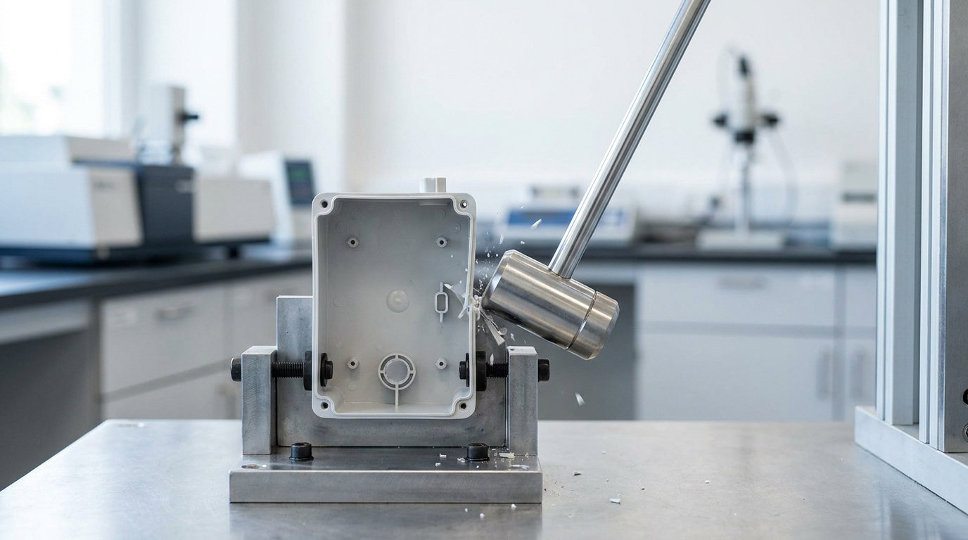
Impact resistance is measured by loading a plastic part or a specimen cut from it with a known, sudden impact and recording how much energy it absorbs before it cracks or breaks. To learn how to test plastic parts for impact resistance, you define a pass or fail criterion, pick a method that matches the way the part fails in service, condition representative specimens, and then measure absorbed energy rather than guessing from appearance. A full pendulum program takes a couple of hours of setup and testing; a shop-floor drop screen takes minutes.
The tricky part is rarely the machine. It is testing something that represents the part you actually ship, and knowing what the number means. This guide walks through the process, the standards behind it, and how to read the result.
Table of Contents
- What You Need
- Step-by-Step: How to Test Plastic Parts for Impact Resistance
- Common Mistakes
- Frequently Asked Questions
- What is the ASTM standard for impact testing?
- What is the difference between an Izod impact test and a Charpy impact test?
- How do you perform a notched Izod impact test?
- How do you perform a notched Charpy impact test?
- Which plastic has the highest impact strength?
- Why are notched impact values lower than how the part actually performs?
- Conclusion
What You Need
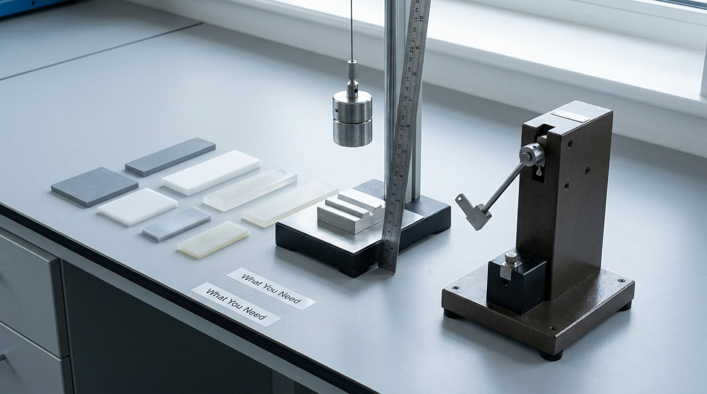
Gather these before you cut a single specimen. Missing one item mid-run is the fastest way to produce a set of results you cannot use.
- Representative material or parts. Several parts from the production lot, not a clean sample someone kept in a drawer. If the target is molded components, keep the parts as molded rather than machining them into bars.
- A pendulum impact tester with a capacity that suits the material. Common capacities are 2 J, 5.5 J and 10 J. Choose a machine where the expected absorbed energy lands roughly in the middle third of the range, and never above about 80 percent of nominal energy.
- Drop test equipment for finished parts: a rigid base plate, a height gauge or scale, a release clamp, a rigid striking surface and a timer, plus foam to protect eyes and hands.
- A notching machine and broach set, or a small mill with a fine cutter, if you are running notched tests. Notch geometry has to be repeatable, and a hand file will not get you there.
- Measurement tools: a micrometer reading to 0.01 mm for specimen width and thickness, calipers for length, and a notch gauge or optical comparator to verify the notch root radius and depth.
- Conditioning supplies: a temperature and humidity chamber, desiccant or a controlled-humidity cabinet, and a dry-room or desiccator for storage after conditioning.
- Safety equipment: the machine’s interlocked enclosure, safety glasses, and a shield for notching operations. A pendulum at 10 J is genuinely dangerous.
- Reference standards: copies of ASTM D256 and ASTM D6110, or ISO 180 and ISO 179-1, plus ASTM D618 or ISO 291 for conditioning. A verified reference specimen is the fastest way to confirm the machine is behaving.
Step-by-Step: How to Test Plastic Parts for Impact Resistance
1. Define the test objective and failure criterion
Start by writing down what “failure” means for your part, because it decides everything downstream. Common criteria are a through-crack, a broken or snapped feature, a permanent deformation beyond a set depth, a hinge that no longer closes, or a loss of sealing.
Write the criterion as a number where you can. A useful statement reads: no through-crack at any snap-fit arm after a 1.0 m drop onto steel at 23 degrees C, tested on six parts per lot. Vague criteria produce arguments later, usually between engineering and purchasing.
Then note the service conditions the part must survive: lowest and highest temperature, moisture exposure, load direction, and the energy level you expect. Polyamides, polycarbonates and polyesters behave very differently when cold and wet than they do at 23 degrees C on dry conditioning.
2. Select the appropriate test method
There are two families of impact test, and choosing between them is mostly about geometry. Pendulum tests on machined bars give comparable, standardized numbers for ranking materials. Drop weight and dart tests on finished parts or film answer the question of whether a specific component survives a specific event.
| Feature | Notched Izod | Notched Charpy |
|---|---|---|
| Specimen support | Clamped vertically at one end, cantilever | Resting horizontally on two supports, typically 62 mm apart |
| Striker position | Free end, above the notch | Centre of the span, on the face opposite the notch |
| ASTM standard | ASTM D256 | ASTM D6110 |
| ISO equivalent | ISO 180 | ISO 179-1 |
| Reported unit | J/m, often shown as kJ/m2 | J, sometimes kJ/m2 for the notched variant |
| Use it for | Ranking grades, screening incoming lots, most datasheet comparisons | Values comparable with metal testing history, two-point support studies |
Use notched Izod as your default for plastic. It is the number printed on most resin datasheets, so it is what your material supplier quotes and what your engineering team will recognise.
For finished parts, use drop weight, falling dart or a component-level method. DIN 53435 Dynstat is worth knowing about because it handles very small 10 x 15 mm specimens, which helps when you cannot machine a standard bar out of a thin wall. For films and packaging, the falling dart test is the standard choice.
3. Prepare representative specimens and condition them
Test the parts or specimens that represent production, and record where each one came from. For molded components, note the flow direction and the position relative to any weld line, because a part cut across the flow gives a completely different answer from one cut along it.
If you are cutting standard bars, the common test bar is 63.5 mm long, 12.7 mm wide and 3.2 mm thick. Machine the notch to the geometry below, then check the root radius and depth on at least a few specimens with a gauge or comparator.
| Notch type | Depth | Root radius | Included angle | Typical use |
|---|---|---|---|---|
| Type A V-notch | 2 mm | 0.25 mm | 45 degrees | Default for most thermoplastics |
| Type C U-notch | 5 mm | 1 mm | Not applicable | More forgiving, useful for tougher or filled grades |
Condition specimens before testing, following ASTM D618 or ISO 291. State the procedure in your report, because two laboratories conditioning the same material under different regimes can report numbers that differ by a wide margin. Let the specimens acclimatize in the test environment before the first swing; a cold bar reads lower than the same bar at room temperature.
4. Run the impact test
For Izod, clamp the specimen at the bottom of the fixture, position the striker to hit the free end directly above the notch, zero the dial gauge or encoder, and release the pendulum. The machine derives absorbed energy from the difference between the release height and the height the pendulum reaches after the fracture, in the form K = mg(h minus h’).
For Charpy, lay the specimen across the two supports, put the notch on the face opposite the striker, set the span, and release so the pendulum strikes the centre of the specimen. Record the energy in joules.
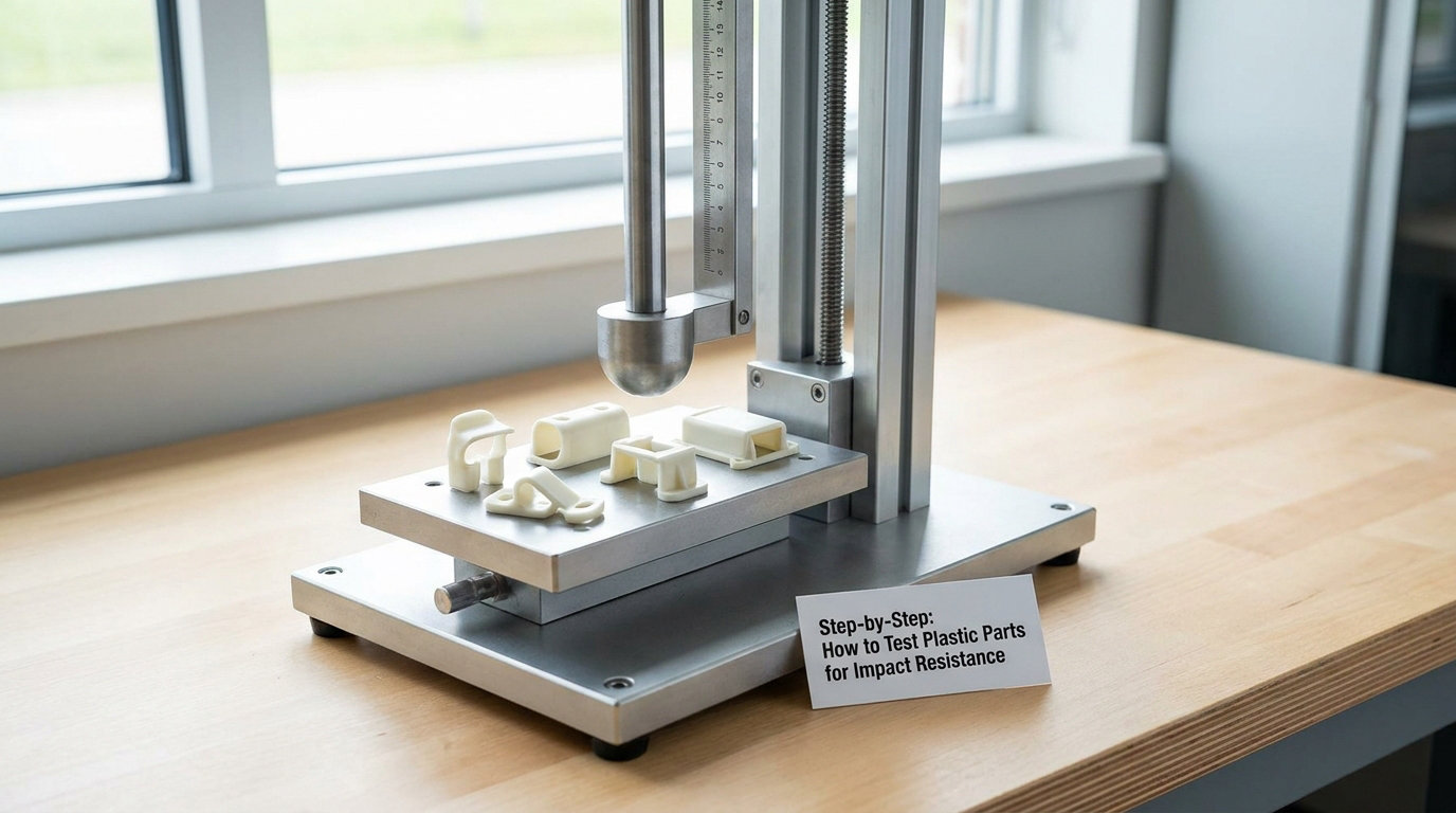
For a drop test, set the striking surface to the height your criterion requires, secure the part in a fixture that matches its real orientation, and release. Keep the impact face, the strike material and the contact geometry identical for every part in the series. Rotating the part between drops quietly changes the test.
Work at a steady pace. Fatigue of the operator, not the machine, is often what makes two labs disagree.
5. Measure and interpret failure
Record the absorbed energy, the type of break, and the visible condition of the fracture surface. Ductile fracture in a thermoplastic usually shows a drawn, whitish, torn appearance with lateral contraction and shear lips. Brittle fracture looks flat, with cleavage facets radiating from the notch and very little deformation.
Compare your result against typical notched Izod values so you can tell whether the number is plausible. Unmodified polycarbonate and ABS sit at the high end among common thermoplastics, while homopolymer polypropylene, polystyrene and rigid PVC are far lower and tend to fail in brittle fashion.
| Material | Typical notched impact range | Character |
|---|---|---|
| Polycarbonate (PC) | 8 to 15 kJ/m2 | Ductile, tough |
| ABS | 6 to 10 kJ/m2 | Ductile to mixed |
| ABS/PC alloy | 10 to 18 kJ/m2 | Ductile, tough |
| Polypropylene (PP) homopolymer | 2 to 5 kJ/m2 | Mixed, notch sensitive |
| PP copolymer | 5 to 10 kJ/m2 | Ductile |
| Polyoxymethylene (POM) | 4 to 8 kJ/m2 | Semi-brittle |
| Polyamide (PA6) | 4 to 10 kJ/m2 dry, lower when conditioned | Ductile when dry, tougher wet, notch sensitive |
| PET | 3 to 7 kJ/m2 | Mixed to brittle |
| PVC-U rigid | 2 to 5 kJ/m2 | Brittle |
| Polystyrene (PS) | 1 to 3 kJ/m2 | Brittle |
Keep notch sensitivity in mind while reading these numbers. A 2 mm V-notch deliberately creates triaxial stress and a stress concentration, so the result is a lower bound on how the part behaves under a smooth, distributed blow. That is the point of the test: the notch models a flaw. It also means a material with a sharp notch drop-off can look far worse in the lab than in the finished part.
Conversely, a notched bar never captures the effects of geometry. A housing with a sharp internal corner, a thin hinge or an inconsistent weld line will fail sooner than any datasheet value predicts. When a molded part fails in service and the bar test looks fine, the cause is nearly always geometry or weld-line strength rather than the resin.
6. Repeat, compare, and report results
Test a full set of specimens rather than one part. ASTM D256 calls for ten specimens with at least five complete fractures for a valid report, and most people treat ten as a sensible minimum for screening too. For drop tests on finished parts, six or more parts per lot is a reasonable starting point.
Report the mean, the standard deviation and the individual values. A single outlier is information, not noise, and hiding it behind an average destroys the signal you were looking for. Calculate a pass rate when your criterion is pass or fail, and report the worst single result alongside the mean for design work.
A usable report states the standard and its edition, specimen dimensions, notch geometry, conditioning regime, temperature at test, pendulum capacity, number of specimens, individual results, mean, standard deviation and the fracture appearance. It also names the part orientation and where each specimen was taken from.
For work that needs external credibility, send a subset to an ISO/IEC 17025 accredited laboratory. A lab can run tests across a temperature series, produce force-deflection data with instrumented equipment, and give you a document your customers will accept. Screening parts in-house first means you only pay for the runs that need signing off.
Common Mistakes
Most disappointing impact results trace back to one of these, and each has a straightforward fix.
- Testing a convenient sample instead of a production part. A clean, straight, generously radiused sample is not the part. Fix: test parts from the current lot and record flow direction and weld-line position.
- Notch geometry out of tolerance. A root radius of 0.4 mm instead of 0.25 mm changes the result noticeably. Fix: verify the notch on a gauge or comparator before testing, and re-machine any specimen that is out.
- Skipping or abbreviating conditioning. Fix: follow ASTM D618 or ISO 291, and let specimens acclimatize in the test environment before the first swing.
- Testing at an uncontrolled temperature. A pendulum left near a window in winter will report a lower value than the same material in summer. Fix: record temperature with every result and run a temperature series when the part ships cold.
- Wrong pendulum capacity. Too little energy and the specimen does not break; too much and it flies out of the valid range. Fix: pick a capacity where expected absorbed energy sits near the middle of the scale.
- Poor fixture alignment or a miscalibrated machine. Fix: check the striker’s path against the notch, verify friction and potential energy against a reference specimen, and schedule calibration on a known schedule rather than after a dispute.
- Treating one result as conclusive. Fix: run the full specimen count and report the spread, not just the best result.
- Ignoring support span errors in Charpy testing. A span set a few millimetres off changes the result. Fix: confirm the span setting against the standard before each run.
Two habits pay off quickly. Run a reference specimen at the start of each session to confirm the machine, and keep a small log of every set of results with the machine, operator and date. Six months later, that log is what tells you whether a change in the incoming material is real or just noise.
Frequently Asked Questions
What is the ASTM standard for impact testing?
ASTM D256 is the main standard for notched Izod impact resistance of plastics, with ISO 180 as its international equivalent. ASTM D6110 covers notched Charpy impact for plastics, paired with ISO 179-1, and ASTM D1822 covers tensile impact properties. Other referenced methods include ASTM D5420, D1709 and D2444 for thermosets and films. ASTM E23 and ISO 148-1 cover metals rather than plastics.
What is the difference between an Izod impact test and a Charpy impact test?
In an Izod test the specimen is clamped vertically at one end in a cantilever arrangement and struck at its free end above the notch. In a Charpy test the specimen lies horizontally on two supports and is struck in the centre on the face opposite the notch. Izod reports energy per unit notch length in J/m under ASTM D256 and ISO 180; Charpy reports total absorbed energy in joules under ASTM D6110 and ISO 179-1.
How do you perform a notched Izod impact test?
Condition the specimen per ASTM D618 or ISO 291, then machine a Type A V-notch 2 mm deep with a 0.25 mm root radius at a 45 degree included angle. Clamp the 63.5 x 12.7 x 3.2 mm bar at its lower end in the cantilever fixture, align the striker above the notch, zero the readout, and release the pendulum. Record the absorbed energy in J/m and note the fracture appearance.
How do you perform a notched Charpy impact test?
Place the notched specimen horizontally on the two supports with the standard span, usually 62 mm, and orient the notch on the face opposite the striker. Position the pendulum so it strikes the centre of the specimen, release, and let the machine calculate absorbed energy from the swing heights. Report the result in joules and check that the pendulum was operating inside its valid energy range.
Which plastic has the highest impact strength?
Among common thermoplastics, unmodified polycarbonate and ABS are the toughest. Polycarbonate typically reports 8 to 15 kJ/m2 notched Izod, ABS around 6 to 10 kJ/m2, and ABS/PC alloys a little higher. Homopolymer polypropylene, polystyrene and rigid PVC sit far lower, generally 1 to 5 kJ/m2, and tend to fracture in brittle fashion. Additives and conditioning change these figures considerably.
Why are notched impact values lower than how the part actually performs?
A sharp notch creates a stress concentration and puts the material into a triaxial stress state, so it is deliberately the harshest condition you can impose on a bar. The value is a lower bound that models a flaw, not a prediction of a smooth blow on a real component. A part with generous radii and even walls will usually absorb more energy than its notched bar value suggests.
Conclusion
Start with the service requirement, not the machine. Write down the energy or drop height the part must survive and the failure you would count, choose a representative geometry and the matching standard method, then produce a documented set of results on several production parts.
Only when that baseline exists does it make sense to change material or design. Radii, wall thickness and weld-line placement usually move the number further than a resin swap does, and you will not know which one to fix without repeatable data behind it. Updated for 2026.