
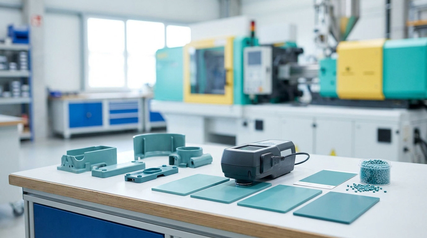
To match plastic color across production runs, you control four variables at once — resin lot, colorant lot, processing conditions and mold surface condition — then check every batch against one written, retained standard with instrument readings instead of a visual opinion. Set the standard before the first shot, lock the material and the process window, measure, trend the readings, and document it all.
Color is the fastest visible quality signal on a cosmetic plastic part. It is also the easiest thing to argue about, because two people can look at the same part and see two different colors, and both be right about what they see.
The method below removes the argument. It is the approach we see work on repeat and multi-year programs: one signed reference, fixed conditions, an agreed numeric limit, and a written record of every change that touched the part.
Table of Contents
- What You Need
- Step-by-Step: How to Match Plastic Color Across Production Runs
- How to Match Plastic Color Across Production Runs: Establish the Standard
- Control the Material and Processing Conditions
- Compare Samples Under Consistent Conditions
- Measure Color and Set Objective Limits
- Validate the First Run and Subsequent Production
- Inspect, Trend, and Correct Drift
- Document the Result and Prevent Future Variation
- Common Mistakes
- Frequently Asked Questions
- What is a good Delta E value for molded plastic parts?
- What causes color drift between injection molding runs?
- How do you retain a plastic color standard?
- Why do two parts from the same batch look different?
- How do I compare a new resin or masterbatch lot against an approved color?
- Can mold wear change the color of molded parts?
- Conclusion
What You Need
You need five things before the comparison is meaningful: a written color specification, a physical master sample, a measuring instrument, a controlled viewing environment, and a record system that survives staff changes.
- A written color specification. CIE L*a*b* target values, a tolerance limit expressed as Delta E (preferably CIEDE2000, written dE00), the surface texture standard, the nominal wall thickness, and the illuminant the part will be judged under. Pantone or RAL references are useful for picking a starting color; they are not a control specification for molded plastic, because a Pantone chip is a different material, thickness and gloss.
- A physical master sample. A plaque or chip molded on the production tool, with the production resin, production masterbatch addition rate and nominal process window. Make several, not one. Sign and label each with date, tool, cavity, material lots and instrument reading.
- A benchtop spectrophotometer with a d/8 integrating sphere, a 10-degree observer, and both SCI (specular included) and SCE (specular excluded) measurement modes. Aperture size should suit the part: a broad flat panel can be read at 8 mm, a thin clip or curved handle needs a smaller aperture or a fixture.
- A color viewing booth with at least a daylight-equivalent source. Add a store/office illuminant if the parts ship to retail, and a UV-filtered option for outdoor parts.
- Storage and labelling kit. Black, opaque boxes or sleeves that block light, foam-lined sample bags, and labels that record tool, cavity, date, lots and the dE00 reading at the time of approval.
- A calibration reference. A white tile checked against a certified standard on a fixed interval, and a log of the check.
- A mold maintenance log and a tolerance log that a customer or auditor can read, showing when the tool was polished or repaired and whether appearance was re-verified afterwards.
A hand-held colorimeter is fine for screening and too noisy for a release decision. Buy or borrow the spectrophotometer, and hold the viewing booth and the instrument together in the same room when you can, because backlighting and ambient light corrupt visual comparisons even when the instrument is fine.
Step-by-Step: How to Match Plastic Color Across Production Runs
How to Match Plastic Color Across Production Runs: Establish the Standard
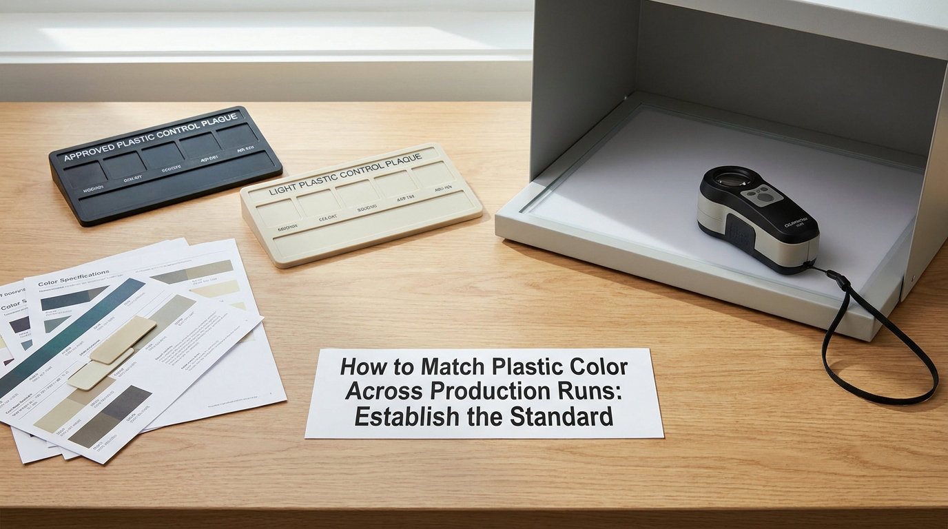
Color matching starts when you decide which document governs, because if two specifications exist, every dispute has a winner.
Name one governing specification and freeze it. On it, record the L*, a* and b* targets, the dE00 limit, the surface texture grade, the nominal wall thickness, the instrument mode and geometry, the number of measurement spots, and the viewing illuminant. Anything you do not write down will be reinterpreted later by whoever is arguing.
Then create the master sample. Mold it on the actual tool, from the actual resin and masterbatch lot, at the nominal process window, using the standard gate and the nominal wall thickness. A plaque made on a lab press will not match production, and a plaque from a different tool with a different texture will not either.
Sign it, label it, and read it on the instrument. That first reading is the baseline. Store the masters out of daylight, away from UV sources and heat, wrapped so nothing scratches the face you measure. Read a stored master every few months; a physical standard fades, yellows and picks up scratches, and a standard that has moved is worse than no standard. If it drifts more than about 0.5 dE00 from its baseline, mold a replacement and retire the old one.
Decide how long the standard stays valid. A good default is to re-verify the master at every tooling maintenance event and at least once a year for active programs, and to re-approve the standard whenever the resin supplier, resin grade, masterbatch supplier, colorant formulation or mold cavity finish changes.
Control the Material and Processing Conditions
Most color problems are set before the resin reaches the cavity, so control the material and the machine before you look at parts under a light.
On the material side, fix the resin grade and record the melt flow index (MFI) of every incoming lot. Resin lots vary in base color and in molecular structure, and MFI shifts the shear history, which shifts pigment dispersion. Record the masterbatch lot number and verify tinting strength on first receipt of a new lot, because a batch that is a slightly weaker or stronger tint will move the color at the same addition rate. Masterbatch addition rates typically sit between 1 and 6 percent, with roughly 1 to 3 percent for dark, saturated colors, so a dosing error of a few tenths of a percent is a real color change on a dark shade.
Use gravimetric dosing where the program justifies it. Gravimetric feeders hold addition-rate accuracy to roughly plus or minus 0.5 to 1.0 percent, against plus or minus 2 to 4 percent for volumetric units, and on dark colors that difference is visible. Pre-mix or tumble-blend the masterbatch before the hopper so segregation in the feed does not become banding in the part. Check pigment agglomerate size against your specification: below 10 to 20 microns is generally acceptable, and below 5 microns is the target for premium appearance. If your melt temperature is high enough to stress the colorant, check the pigment’s thermal stability before running, not after.
On the process side, write down a window, not a single setpoint: barrel zone temperatures, melt temperature, screw speed, back pressure, injection speed, pack pressure and time, mold temperature, cooling time, and cycle time. A melt temperature shift of as little as 5 degrees C can produce a color difference a customer will see. Hold time matters too, because pigment degradation shows up first as a shift toward yellow or a loss of brightness. Record the regrind or recycled content percentage as a controlled variable, and dry hygroscopic resin to the supplier’s specification every time rather than trusting a moisture meter reading from last shift.
On the first shot with any new resin or masterbatch lot, do not run production. Make a first article, condition it, and compare it to the master under the qualified process window. If it sits inside the agreed dE00 limit, record that lot as the new baseline for the program.
Compare Samples Under Consistent Conditions
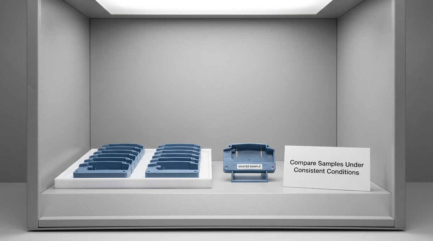
A color comparison is only valid if both samples arrive in the same condition, and molded plastic changes measurably in the hours after it leaves the tool.
Condition samples before you read them. Standard conditioning of roughly 24 hours at 23 degrees C and 50 percent relative humidity lets residual stress relax and lets surface moisture and static settle, so the part you measure is closer to the part the customer receives. Handle parts with clean, dry hands or gloves; fingerprints read as a color shift on dark and glossy surfaces, and a scuffed matte face reads as a lighter one.
Compare in an approved viewing booth, not under a window and not under the fluorescent tubes over the inspection bench. Daylight at a window is unfiltered and shifts with the weather, and overhead shop lighting is heavily weighted toward whatever lamp is in the fixture. Put the master and the sample side by side, in the same orientation, lit from the same side, on the same neutral background.
Look at more than one spot. Check the wall directly behind the gate, the far end of the flow path, a thick section, a thin section, and a rib or a corner where the resin is stretched thin. Flow lines, weld lines, jetting marks and cold shots are all local. Then look at the same locations in the booth, and record which locations you examined — if you only ever look at the flat panel, you will miss a defect that a customer finds on the curved face.
Measure Color and Set Objective Limits
Instrument readings, not booth impressions, decide whether a batch is in spec — with one caveat: the number has to travel with its settings, or it means nothing.
Measure in CIE L*a*b* and report the difference as dE00 (CIEDE2000). The older CIE76 formula treats every axis as equally important, which overstates differences in lightness and understates hue differences; dE00 weights them the way a trained eye does and is what most current specifications and software default to. State the illuminant and observer (usually D65/10 degrees), the geometry (d/8), the mode (SCI or SCE), the aperture, the number of spots and the averaging method, then freeze them. A dE00 printed without those six items is not a control, it is an opinion with decimals.
Take three to five readings per part at defined locations and average them. Reading one spot on a textured part tells you about that spot. On a textured or matte surface, run both SCI and SCE: SCI includes the surface reflection and reflects what the customer sees, SCE removes it and isolates pigment color, so a gloss or texture change shows up as an SCI/SCE divergence rather than being mistaken for a pigment shift. Measure gloss separately, typically the 60-degree gloss value, and treat gloss as a controlled specification in its own right on cosmetic parts. For light or natural colors, add haze and yellowness index; they catch degradation that L*a*b* alone can miss.
Set the limit by application, not by convention, and agree it in writing before the first production run.
| Application | Typical dE00 limit | What else to control |
|---|---|---|
| Premium cosmetic visible parts | 0.5 to 1.0 | 60-degree gloss, texture depth, SCI and SCE both reported |
| Parts assembled next to each other | 0.5 to 0.8 | Same illuminant, single qualified source or cross-qualified sources |
| Automotive and appliance interior | 1.0 to 1.5 | Haze and yellowness index on light colors |
| Functional housings, non-visible surfaces | 1.5 to 2.0 | Cavity-to-cavity spread still checked |
| Hidden structural parts | 2.0 to 3.0 | Hold within one material lot where practical |
| Film and packaging | 0.5 to 1.5 | Typical film masterbatch guidance range |
| Incoming masterbatch lot check | 0.3 to 0.5 | Tinting strength and dispersion before release |
These are starting points, not scripture. Tighten them where your customers have complained, and loosen them only where the parts are never seen together. Where a number is unavailable, keep the visual booth check in place and record the observer, because informal acceptance is still acceptance.
Validate the First Run and Subsequent Production
Approve color at the first article, then re-verify it on every batch — against the original standard, never against the last shipment.
Run the first article to steady state, not to cavity fill. Take a sample from every cavity on the same shot if the tool has more than one, plus thick and thin sections. Measure against the master with the frozen settings, and let the eyes have the last word in the booth afterwards. A cavity-to-cavity spread larger than your limit is a mold problem, not a measurement problem, and it will not average out across the tool.
Once the first conforming run is approved, write the mean and the control limits down — the mean plus and minus three sigma of the conforming data, or your dE00 limit, whichever is tighter. Keep parts from the approved run as the reference set. Anything measured against them later, including the samples the customer keeps, is traceability, not just a spare.
Here is why the last-shipment comparison fails. Suppose each batch drifts 0.3 dE00 from the one before and always in the same direction. Every batch passes its own comparison and every certificate of analysis says “conforming”. After twenty batches you are more than 1.3 dE00 from the color the customer signed, and a skin-tight cosmetic program no longer looks like the approved part. The drift is invisible batch by batch and obvious across the program, which is exactly why each batch must be read against the original master.
Re-verify at startup after any changeover, at the intervals your volume justifies (hourly for a cosmetic program is not unreasonable), and after every stoppage long enough to affect melt temperature. One reading per batch is a release record; three readings across the run, at the same marked locations, is what tells you the run did not wander in the middle.
Inspect, Trend, and Correct Drift
Drift is easiest to fix in the first hundred shots and nearly impossible to fix in the last thousand, which is why inspection is scheduled rather than reactive.
Take samples at startup, at fixed intervals during the run, and at the end. Trend the readings by machine, by cavity, by material lot and by shift, so that a step change lines up with a resin delivery and a slow ramp lines up with a heater band. A chart beats a spreadsheet here: a control chart shows a tool that is drifting before a customer does.
When a reading goes out, check the matrix below and change one variable at a time. The most common sequence that works is material lot first, then colorant lot and dosing accuracy, then melt temperature and hold time, then mold condition. Two changes at once tells you nothing when the part comes back in spec.
| Symptom | Likely cause | Verification test | Fix |
|---|---|---|---|
| Visible color specks | Undispersed pigment, agglomerates, contaminated regrind | Cut the part and inspect the section; check the regrind and the feeder | Improve pre-mixing and dispersion, clean the hopper, quarantine suspect regrind |
| Streaks or marbled tone | Poor dispersion, damp resin, high shear at the screw | Check the drying record and barrel log; run a first shot at lower screw speed | Dry resin to spec, lower screw speed, raise melt temperature within limits |
| Washed-out or lighter color | Under-dosing, low melt temperature, short hold | Weigh the feeder output over a fixed time; check the addition rate setting | Correct the addition rate, then step melt temperature up a few degrees at a time |
| Darker or warmer tone | Over-dosing, high melt temperature, long residence time | Check feeder calibration and cycle time against the qualified window | Reduce addition rate or hold time before touching anything else |
| Yellowing or whitening | Thermal degradation, excess regrind, moisture, wrong resin grade | Check regrind ratio, melt temperature and the incoming resin certificate | Lower melt temperature, cut regrind, change resin grade |
| Same color, different gloss | Cavity wear or repolish, vent change, cooling variation | Measure 60-degree gloss; inspect the cavity surface | Restore the cavity, reset cooling time, re-qualify appearance |
| One cavity differs from the rest | Flow, venting or packing difference between cavities | Measure cavity to cavity on the same shot | Balance vents, packing and cooling; check for flash |
| Color fine run to run, but off overall | Each batch approved against the previous shipment | Measure the last three retained samples against the original master | Re-baseline on the original master and re-verify the retained set |
| Looks wrong under store lighting | Metamerism between the part and the target | Compare dE00 under daylight and store illuminants in the booth | Re-specify the target to retail lighting or change colorant system |
One trap catches experienced people: process-window defects get misread as color problems. Practitioners on the Practical Machinist forums describe fixing poor-looking moldings by reducing cavity pressure, running the mold cold and lowering barrel temperature — those are flow and surface fixes, not color fixes. Before you adjust a single gram of masterbatch, put the part under the booth and look for cold shots, flow lines and gloss banding. If the color reading is normal and the surface is wrong, you have a molding problem.
Make corrections deliberately and retest against the master. If two controlled attempts fail, stop adjusting and re-qualify from the master with a fresh first article rather than drifting further.
Document the Result and Prevent Future Variation
The record is what makes the next run a repeat instead of an experiment, and it is the part most often missing when a program goes wrong.
For every approved run, keep: the accepted standard reference and its storage location, the resin and masterbatch lot numbers, the masterbatch addition rate, the process settings, the sample IDs and cavities they came from, the instrument settings and readings, any deviation, the corrective action, and the sign-off. A color control plan is only as good as the last entry in it.
Put change control around the four inputs. A new resin supplier, a different MFI range, a masterbatch reformulation, a carrier resin change, a new texture or polish on a cosmetic cavity, a gate insert swap, a vent repair — each of those is a documented re-qualification trigger: first shot, measure, compare to the retained master, record, release. Tooling maintenance that changes the surface of a cosmetic cavity changes apparent color, so a polish should never be logged as a housekeeping entry with no appearance check attached.
Keep retained samples. Store parts from the approved run at both ends of the program when supply crosses borders or time zones, so a dispute a year later can be settled with instrument data on both sides rather than with photographs on a phone. Digital spectral records are worth keeping alongside the physical masters, not instead of them, since the plaque tells you what the standard looked like in practice and the file tells you what it measured.
Common Mistakes
Almost every avoidable color dispute traces back to one of these.
Approving against the last shipment. Each batch passes, and the program drifts. Fix: every batch is measured against the original retained master; the previous shipment is a traceability sample, not a standard.
Comparing parts of different thickness or texture. A thicker wall looks darker and a matte face looks lighter, so the comparison is measuring geometry, not pigment. Fix: compare like with like, and use a calibrated plaque where the part itself is not a flat, consistent surface.
Changing several process variables at once. You get a better part and no knowledge of why, so the next drift is just as hard to solve. Fix: one variable per first shot, and log each one.
Treating Delta E as a universal pass-fail rule. A single number across every application guarantees arguments on hidden parts and false confidence on cosmetics. Fix: dE00 limits set per application, paired with gloss, haze or yellowness where the part needs them, and written down before production.
Judging color in uncontrolled light. Daylight through a window, shop fluorescents and a phone screen each add their own bias. Fix: a viewing booth, the same orientation, the same neutral background, and a phone photograph used only for records, never for approval.
Approving color with no process record. If the accepted color is not tied to a lot number, an addition rate and a set of settings, the next run starts from nothing. Fix: the first-article record travels with the standard.
Chasing a surface defect with a color change. Cold shots, flow lines and gloss banding look like color problems and get fixed with pigment, which then makes the real defect worse. Fix: look for localized surface evidence in the booth before changing anything in the feeder.
Frequently Asked Questions
What is a good Delta E value for molded plastic parts?
For most molded parts, an agreed dE00 limit between 0.5 and 1.5 covers the work. Use roughly 0.5 to 1.0 for cosmetic visible surfaces and parts that sit next to each other, and up to 2.0 to 3.0 for hidden or functional housings. Always specify the formula, illuminant, instrument mode and surface, because a number without those details is not a control.
What causes color drift between injection molding runs?
Four families: the resin lot, the colorant lot, the process, and the mold. A different grade or melt flow index, a masterbatch lot with different tinting strength, a melt temperature shift of as little as 5 degrees C, dosing error, longer hold time, or a worn or repolished cavity will each move the color. Change one variable at a time when you hunt for the cause.
How do you retain a plastic color standard?
Keep several signed plaques or chips from the approved run, molded with the production resin, masterbatch and tool. Store them wrapped, out of daylight, UV light and heat, in a light-blocking box, labeled with date, tool, cavity, lots and the reading taken at approval. Read a stored master every few months and replace it if it has moved more than about 0.5 dE00.
Why do two parts from the same batch look different?
Usually the surface rather than the pigment. A textured or matte face reflects more or less light than a polished one, so the same pigment reads darker or lighter, and wall thickness, gate area and flow lines shift apparent color too. Metamerism means two parts that match under one illuminant can separate under another. Measure in both SCI and SCE with a fixed geometry.
How do I compare a new resin or masterbatch lot against an approved color?
Make a first shot with the new lot inside the qualified process window, condition it for about 24 hours, then measure it against the retained master using the same instrument settings. Inside the agreed dE00 limit, record that lot as the new baseline. Outside it, adjust the colorant addition rate or the resin base color and repeat the comparison rather than accepting the drift.
Can mold wear change the color of molded parts?
Yes. Polishing, EDM work, a vent repair, a new gate insert or a flashed cavity all change surface gloss and local thickness, and apparent color follows both. Treat any maintenance on a cosmetic cavity as an appearance change: run a first shot, measure it against the retained master, and file a re-qualification record before the next production release.
Conclusion
Start by writing down one color standard: target L*a*b* values, a dE00 limit chosen for the application, the texture and thickness it applies to, and the instrument settings that will be used to read it. Then mold a master on the production tool, sign it, label it and store it where light cannot reach it.
From there the work is discipline, not clever measurement. Control the resin lot, the masterbatch lot and the addition rate; fix the process window; measure every batch against that master rather than the last shipment; trend the readings; and record every change that touched the part. Do those things and color consistency stops being an argument you have every quarter.