
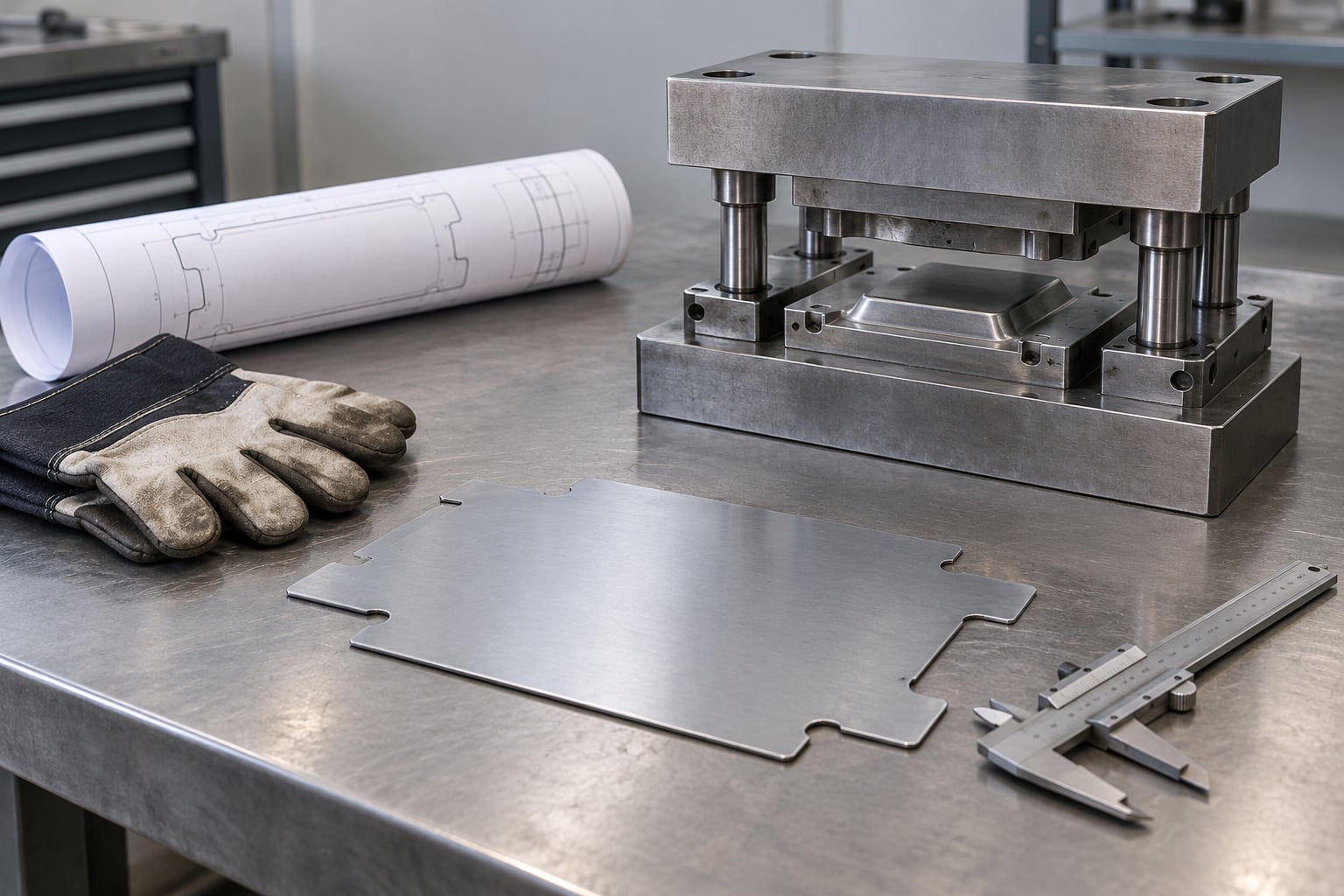
Metal stamping is a cold-forming process: a mechanical or hydraulic press pushes sheet metal against a hardened steel die that cuts, bends, embosses or draws the metal into a finished part. Here is the metal stamping process step by step, from the drawing review that starts a job to the quality sign-off that closes it.
- Review the part drawing and define requirements
- Prepare and inspect the metal material
- Design the stamping die and tooling
- Set up the press and run the first pieces
- Form the features through progressive operations
- Perform in-process quality checks
- Inspect, deburr, finish and package the parts
- Approve the production run and maintain the process
Most buyers meet the process at the wrong end. They get a quote, approve a sample and only later find out that a hole sits too close to a bend line or that the run cannot hold tolerance at volume. Knowing where the checkpoints are makes those conversations much shorter.
Table of Contents
- What You Need
- Metal Stamping Process Step by Step
- 1. Review the Part Drawing and Define Requirements
- 2. Prepare and Inspect the Metal Material
- 3. Design the Stamping Die and Tooling
- 4. Set Up the Press and Run the First Pieces
- 5. Form the Features Through Progressive Operations
- 6. Perform In-Process Quality Checks
- 7. Inspect, Deburr, Finish, and Package the Parts
- 8. Approve the Production Run and Maintain the Process
- Common Mistakes
- Frequently Asked Questions
- What to Do First on Your Next Stamping Job
What You Need
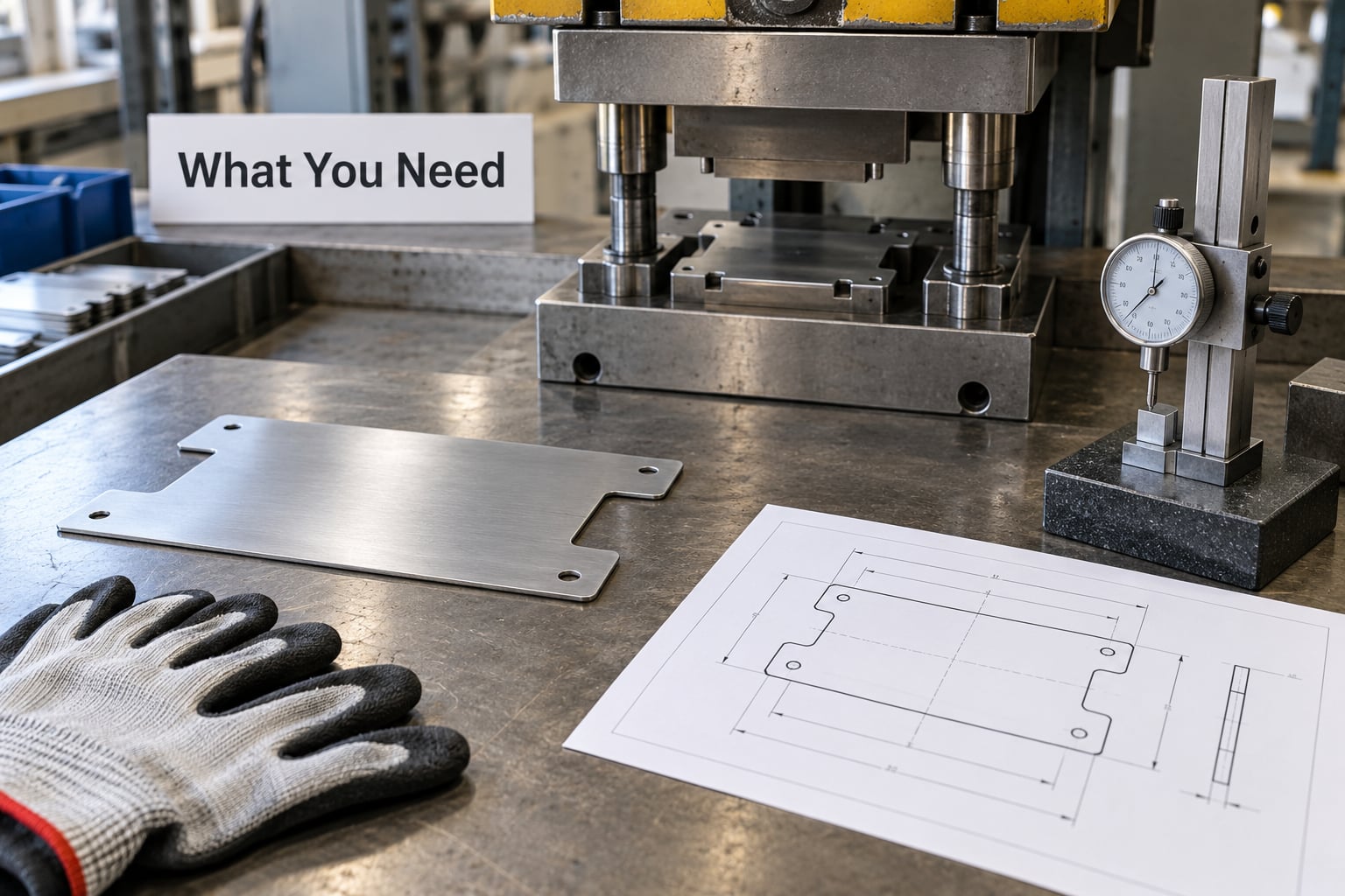
Tooling is the expensive line item, so nothing should be released for cutting metal until the documentation below is settled in writing.
- Drawings: a dimensioned print or 3D model with a flat blank size, marked critical features and a tolerance callout on each dimension that matters.
- Material specification: grade, thickness, temper, coating or plating, and whether you supply the material or the stamper does.
- Tooling inputs: expected part volume per year, the required output per press hour, and any existing tooling you want modified rather than built new.
- Inspection requirements: which characteristics are critical, what sampling frequency applies, and whether you need full inspection, first-article plus sample, or SPC on selected dimensions.
- Production planning: the date you need first articles, the annual run rate, and whether the part ships domestic or export. Export adds documentation and packaging lead time.
- Supplier documentation: control plan, material certificates, dimensional reports, and the change-notification process you want in place.
If you are qualifying a shop rather than a single job, the same checkpoints show up in how to choose a contract manufacturer.
Metal Stamping Process Step by Step
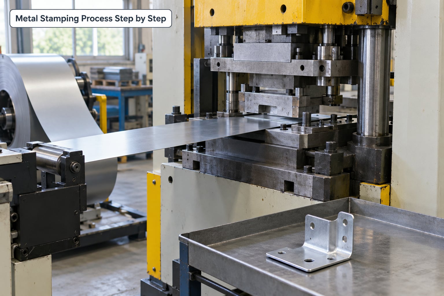
This table is the whole job on one line per station. It is the format I ask for from any stamper before tooling starts.
| Step | What happens | Tooling | QC checkpoint |
|---|---|---|---|
| 1. Drawing review | Dims, tolerances, material and features are confirmed | None yet | Signed drawing and DFM response |
| 2. Material prep | Coil or sheet is verified, cleaned and fed | Coil cradle, straightener, feeder | Incoming material check |
| 3. Die design | Punch and die sets are engineered and cut | Progressive, compound or transfer die | Tooling sample approval |
| 4. Press setup | Die is mounted, aligned and stroked | Press, bolster, die, guarding | First-article trial |
| 5. Forming | Cut, bend, emboss and draw operations run in sequence | Punches, dies, stripper, springs | Station-by-station first piece |
| 6. In-process checks | Parts are measured while the press runs | Gauges, go/no-go fixtures | Sampling per control plan |
| 7. Finish and pack | Deburr, finish, label and package | Deburr tools, finishing line | Final inspection |
| 8. Run approval | Production is released and monitored | Die maintenance, records | Run-at-rate sign-off |
1. Review the Part Drawing and Define Requirements
The review is where you catch the problems that would otherwise become expensive tooling changes. Engineers confirm every dimension, tolerance, material grade, thickness and surface finish against the print.
Two things get missed here more than anything else. First, the flat pattern: a formed part needs a developed blank size, and that number changes with bend allowance. Second, the sequence question, which is covered in step 5.
Ask the stamper to return a design-for-manufacture report. A good one flags holes near bends, tight radii, undercut features and any tolerance the process cannot realistically hold.
2. Prepare and Inspect the Metal Material
Incoming material is checked for grade, thickness and surface condition before anything runs. Thickness is the number that quietly drives everything downstream, because clearance, tonnage and springback all scale with it.
Coil goes through a straightener and gets a light protective oil before it reaches the feeder. Sheet parts get deburred edges and a flat stack. Either way, the handler looks for rust, scale, roll marks, edge damage and flatness problems, because a coil with a memory will not make a flat bracket.
Practitioners quote clearance values anywhere from 5% to 15% of sheet thickness, with tighter numbers pushing punch wear up and edge cracking up with it. For ordinary work, 8% to 10% per side is the usual starting point. Design rules worth having in your head: minimum hole diameter around 1.2x to 2x thickness, slot width at least 1.5x, inside corner radius at least 0.5x, and hole edges set back roughly 2x thickness from the part edge.
3. Design the Stamping Die and Tooling
The die is the heart of the job. In a progressive die, each station does one operation and the strip advances a fixed pitch per stroke; a compound or transfer die is chosen when the part is shallow, needs a different material orientation, or when the geometry will not release cleanly from one station.
Tooling material is picked against volume. Tool steel carries short and medium runs, carbide pays off at tens of thousands of parts and up. The set is machined, then the cutting edges are finished by wire EDM where the profile demands it, and heat treated to hardness.
Guide posts, springs and shims set alignment and the stripping force. You want a tooling sample reviewed before the die goes to steel, because changing a feature at sample stage is cheap and changing it after the die is hardened is not.
4. Set Up the Press and Run the First Pieces
Press selection follows the work. Mechanical presses run mechanical, transfer and high-volume progressive work and hold speed well. Hydraulic presses give slow, adjustable, full-depth strokes, which suits short runs and heavy draws. Servo presses let a program vary stroke and dwell per station and can hold accurate position for die-to-die verification.
Tonnage comes from the projected area of the cut plus the forming force of the bends or draws, with a safety factor on top. Under-sizing the press shows up as a stroke that will not bottom out on thick or hard material, and the die pays for it.
Setup is die install, bolster alignment, stroke and shut-height setting, feeder pitch to match the die, then lubrication. Light, even lubrication matters more than volume: excess lube leaves oil spots that later show up under plating or powder coat. Guards and light curtains get checked before the first stroke.
5. Form the Features Through Progressive Operations
Now the metal actually changes shape, and the order of operations is the part people get wrong. Piercing first and bending second is the standard pattern because bending after piercing keeps the hole round.
Bend before pierce and the hole stretches, flattens or tears. The hole is already a stress concentration, and putting a bend radius through it does the damage. If the design forces the other order, the tool maker compensates with a shaped or crowned punch, and the hole size in the drawing grows to match.
The cut operations work like this. Blanking separates the piece part from the surrounding blank and drops the slug. Piercing or punching makes a hole and keeps the slug. Lancing makes a slit without removing material. Notching removes material from an edge without separating the part. Trimming shears a previously formed edge to final size. Shearing is the general term for cutting by opposed tools.
The forming operations are bending, flanging, embossing, coining and drawing. Air bending forms over a punch with minimal die contact and needs an overbend to offset springback. Bottoming forces the material fully into a tight die, giving the most accurate angle but the highest tonnage. Flanging makes a short edge form. Embossing raises or recesses a shallow feature without cutting. Coining squeezes a precise thickness, often for electrical contact. Drawing pulls material through a die opening to form a cup or shell, and deep drawing demands a draw ring and lubrication or the wall wrinkles.
6. Perform In-Process Quality Checks
The operator checks parts on a fixed interval, not randomly, and the control plan says how often. Visual checks cover burr height and orientation, cracks, flatness, hole position, bend angle and surface marks.
Dimensional checks use go/no-go pins, micrometers, calipers, optical comparators or CMMs depending on tolerance. What most buyers care about is stability, so trend the key dimension instead of only passing or failing it.
Keep the run tied to the press setting. Once a dimension drifts, the fix is usually a die clearance correction, a spring or pad change, or a lubrication adjustment, not a new setup sheet. OEE calculation covers how this kind of process loss shows up on the plant floor.
7. Inspect, Deburr, Finish, and Package the Parts
Burrs come off next. Tumbling, vibratory deburring and belt sanding handle general parts, and precision parts get a manual or abrasive deburr at critical edges. Deburring is specified as a burr height limit, and the number is in the print.
Finishing follows the material and the environment. Deburring, passivation, anodizing, powder coating, electroplating, e-coating, tumbling and PVD all change the part, and the stamping supplier may or may not own that equipment. Plating and coating add thickness, so any dimension measured before finishing needs a note about whether it is pre- or post-finish.
Packaging protects the part in transit. Piece parts on a layer of interleaving paper, boxed by lot and separated by quantity. Label with part number, revision, lot, quantity and date. Export shipments add packing lists, certificates of origin and heat treatment or material certificates, so ask early for the paperwork rather than at the dock.
8. Approve the Production Run and Maintain the Process
Run approval is a run at rate: the press runs at production speed for a defined period, output is measured, and cycle time is confirmed against your target. That is when the real number of parts per hour becomes known rather than estimated.
After approval, the stamper keeps a control plan, retains a set of golden samples, logs first articles and holds records by lot. Tooling gets inspected on a schedule for wear, sharpening and burr growth, and sharpening is planned rather than reactive.
Change control closes the loop. Any change to material, thickness, tolerance or the drawing triggers a notice to you before it ships. That habit is the one I would put at the top of any supplier qualification checklist, and it follows the same pattern as qualifying a new resin supplier.
Common Mistakes
These are the failures that come up again and again, with the fix that actually works.
Cracked corners and tears when bending
Caused by an inside radius smaller than the material can take, a grain direction running the wrong way, or forming high-strength steel too aggressively. Fix the radius to at least 0.5x thickness, orient the bend across the grain when the material has a direction, and add a bend relief notch on L-shaped corners so the bend line does not run into a corner.
Springback angles off target
Forming and then measuring gives you an angle that relaxes once the load comes off, and the gap grows with yield strength and thickness. Overbend by the measured amount for that material and thickness, or switch to bottoming where tonnage allows.
Holes deforming, flattening or tearing
A hole placed before a bend gets pulled by the bend. Pierce before bending, move the hole back to roughly 2x thickness from the bend line, or add a formed tab that keeps the hole away from the bend radius.
Burrs taller than the drawing allows
Clearance too tight produces a secondary shear edge and a burr on both part and slug. Widen per-side clearance toward 8% to 10% of thickness, check that the punch is sharp, and confirm the die is not worn past its sharpening allowance.
Wrinkles or a bulging wall on drawn parts
The blank holder is too light or the draw ratio too aggressive for the material. Increase blankholder force, add a draw ring, and add lubrication. Deep drawing stainless or aluminum needs both.
Tooling that never pays for itself
Short runs with hardwired multi-station dies leave the tooling cost buried in every part. The usual breakeven sits near 1,000 parts, and it moves with part complexity. For low volume, prototype dies, four-slide machines or soft tooling buy time; for a fixed annual profile, a hard tool and a progressive die win.
Stamping a part that should not be stamped
Long continuous sections, open channels, angles and tube are poor stamping candidates because the blank grows and the material fights the tool. Roll forming handles those profiles far better, and machining or extrusion beat stamping for very low volume or full-depth features.
Frequently Asked Questions
What are the 7 steps in the stamping method?
Most shops describe seven core stages: material prep and blanking, piercing, bending or flanging, trimming, drawing, deburring, and final inspection and finishing. In a progressive die these run one per press stroke across stations rather than as separate setups. Design and die engineering come before all of them, and packaging comes after.
What causes burrs on stamped parts?
Burrs come from the shearing process: a punch shears the metal, then the last portion fractures as the break line. Clearance sets the burr height, so tight clearance makes it worse on both the part and the slug. A dull punch, worn die edge and low press speed all raise burr height as well. Specify a burr limit in the print and check it after deburring.
What is punch-to-die clearance and how much should it be?
Clearance is the gap per side between punch and die opening. Industry practice is roughly 8% to 10% of material thickness per side for ordinary cold stamping, though practitioners quote a 5% to 15% working range depending on material strength and edge quality. Too little and the punch wears fast and the part cracks; too much and the part needs extra trim, the force rises, and the cut edge tears rather than shears.
Is stamping cheaper than machining?
At volume, yes, usually by a wide margin. Once the die is paid off, a stamped part carries only material, feed rate and cycle time, while machining removes metal slowly and wastes the rest. Machining wins for prototypes, very low volume and hard materials where tooling cannot be amortized. The crossover is volume-driven, so run a real quote for both rather than assuming.
What are the main disadvantages of stamping?
Four come up repeatedly. Tooling cost is high up front and hard to justify below a few thousand parts. Setup and die changes take hours, so the press is inflexible once a run is committed. Springback makes bend angles material-dependent, and high-strength steels resist forming. And long continuous profiles such as channels and tubes stamp poorly, where roll forming is the better process.
What materials can be stamped?
Most rolled sheet metals: carbon and cold-rolled steel, stainless steel of the 300 and 400 series, galvanized sheet, aluminum alloys, copper, brass and titanium in thinner gauges. Formability drives the answer, and springback, minimum bend radius and ductility differ by grade. High-strength and spring-temper steels usually need more generous radii, more tonnage and tighter process control.
How do I know if my part can be stamped at all?
Send the flat blank size, material, thickness and volume to a stamper for a manufacturability review before paying for tooling. They will check minimum hole size, hole-to-edge distance, bend radii, forming depth and press tonnage against your tolerances. Any drawing that survives that review can be stamped, usually without design changes.
What to Do First on Your Next Stamping Job
Start with the drawing review, not the quote. Get a manufacturability review that checks hole size, hole placement, bend radii and press tonnage against your material and tolerances, and fix anything flagged before anyone cuts steel.
Then agree the inspection plan and the change-control process in writing before the first article. That is where this whole metal stamping process step by step pays off, because every later checkpoint gets cheaper when the inputs were right at the start.