
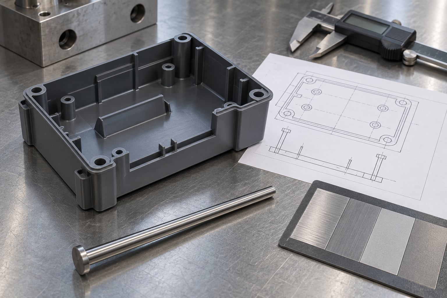
Ejector pin marks are the dimples, glossy rings, whitening or small craters a mold pin leaves behind when the part is pushed out before it has enough stiffness to spring away cleanly. To fix them you have to make the part rigid at the moment of ejection and spread the push over an area big enough to disappear. Geometry first, process settings second, cosmetics standards last.
Knowing how to minimize ejector pin marks starts before anyone touches steel or a process sheet. Most shops get this backwards and start polishing the pin tip. Polishing a witness ring on a part that is still soft at ejection buys you a cleaner-looking dent, not a smaller one. The defect leaves when the local stiffness rises or the contact area grows.
Table of Contents
What You Need
Before anyone touches steel or a process sheet, put these on the bench. Without them you are guessing, and guessing costs more than a week of trial time.
- Mold drawings and the mold print. You need pin numbers, stroke length, pin diameter, pad diameter and whether each pin sits on a rib, a boss or a cosmetic face.
- An approved cosmetic sample. One signed part that quality already accepts, plus the finish class your customer contract specifies.
- Process data for the running tool. Barrel zones, melt temperature, mold temperature, fill time, hold pressure and time, back pressure, cushion and current cooling time.
- A caliper or a feeler gauge set. For wall thickness at each pin pad. If the wall under a pin is thinner than the rest of the part, you have already found your suspect.
- A surface finish comparator or gloss card. Gloss differences around a pin are the fastest visual cue that the surface was stressed rather than merely dented.
- A light box or a fixed-angle inspection lamp. Mark severity is meaningless unless everyone grades it under the same lighting at the same angle.
- Part temperature measurement. An infrared thermometer or a thermocouple in the cavity. Part temperature at the moment of ejection matters more than the cycle timer.
Mark the first bad part with a permanent marker before it gets thrown in the bin. You want that witness in your hand while you are changing settings, not two hours later.
Step-by-Step: How to Minimize Ejector Pin Marks
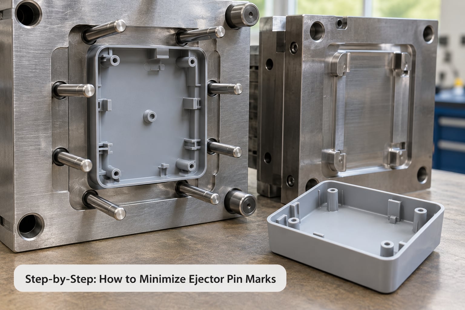
Work in this order because each step assumes the previous one is settled. If you change process settings while the geometry is still wrong, you will spend days proving that nothing matters.
Diagnose the mark and locate its cause
Start by naming the defect, because the name tells you which family of causes to chase. Every witness is one of five things.
- Whitening or stress marks. A pale ring or halo, sometimes with a visible stress pattern. The material yielded and strained under the pin face, usually on a high-impact or colored resin.
- Gloss rings. A shiny circular ring around a flat spot. The surface was compressed and polished by contact rather than deformed, so you are looking at a pressure problem.
- Witness rings and shallow depressions. A circular recess roughly the size of the pin. Over-packed material and too little local wall thickness push into the pin face on release.
- Punch-through. A small hole, tear or crack where the pin pierced a thin wall. Nothing about cooling fixes this one.
- Residue or transfer. A faint film or a colored mark from mold release or from material sticking to a poorly finished pin.
Then map the witness to the tool. Photograph it, note the pin number from the cavity layout, and check what that pin is sitting on: a rib root, a corner, a pocket floor, a gate area or a bare cosmetic face. A mark that repeats on the same pin every shot is a local geometry issue. A mark that jumps between pins or appears on only one shot in twenty is a process window issue.
Two things get confused with ejection marks constantly. Drag marks are long scrapes that run along a surface, caused by the part being dragged across the cavity wall or across a rib as it releases; they point at draft and gate location instead of pin pressure. Sink-like depressions are round, but they form from thick sections shrinking, not from a pin pushing. Our guide to what causes sink marks in injection molded parts covers that second group in detail, and it is worth reading before you disassemble the ejector plate.
Check whether the same pin is under-powered. Compare stroke length across the ejector system. A pin that travels further than its neighbors drives deeper into a section that is already the stiffest load path, and the part rocks around the difference.
Redesign pin placement and mold surfaces
Geometry is where you get permanent results. Nothing in a process sheet survives a mold change, but a correct pad layout does.
Move pins off cosmetic faces onto structurally supported areas. A pin pad belongs on a rib, a wall or a boss, never on a broad flat panel where any witness is visible. When a pad must land on a visible surface, increase the local wall thickness around it; thin walls under a pin are the single most common source of punch-through.
Increase pin diameter and pad diameter together. A wider pin spreads the same ejection force across more area, which drops the contact stress and shrinks the visible mark. The practical floor for general work sits around 3 mm, and complex geometry with ribs needs more. Keep the pin face flat and concentric with the pad so the force does not load one edge of the cavity.
Give the pad proper draft. A pad perpendicular to the part surface fights the ejector on every stroke. Give it at least 0.5 degrees of draft, more on deep pockets where the part also has to clear the wall, and check that the pad does not sit proud of the parting surface where it can drag.
Polish in one direction only, along the ejection axis. Cross-hatched or randomly polished pin faces hold micro-abrasions that print into gloss rings on the next shot. If a witness persists after a proper polish, the pin face or the pad geometry is the problem, not the finish.
When the layout will not cooperate, change the ejector type rather than the resin. An ejector sleeve puts a full annular ring of contact under a deep cylindrical boss instead of one small dot. Blade ejectors and stripper plates spread load across a whole rib. An air poppet that blows the part off the core helps where the part is sticking in a pocket, and reports of successful results land near 60 percent rather than near certain. See how sink marks differ from ejection witnesses before you start swapping pin types.
Optimize ejection speed and machine settings
With geometry settled, tune the process. The goal is a part that is stiff enough to release without a sharp pull.
- Extend cooling time. This is the most direct lever. Going from 20 seconds to 30 seconds cut mark severity on automotive polypropylene door panels in reported trials. Add dwell for stiff or blends: a short dwell in the range of zero to five minutes noticeably reduces whitening in ABS and PVC blends.
- Trim hold pressure and pack time. An over-packed pad behaves like a pressurized cushion; release it and the pin has to push back a live spring. Reduce hold pressure in small increments and watch the part weight.
- Slow the ejector stroke. Fast ejection snaps the part through its draft. A slower stroke with the same final position lets the part peel off gradually and reduces the ring.
- Control mold and melt temperature. Higher mold temperature means lower part stiffness at ejection on many resins. Dropping mold temperature slightly is often cheaper than adding cooling time.
- Watch cushion and decompression. A very small cushion can cause the screw to bottom out and slam the part. Leaving decompression distance lets the melt relax at the gate instead of springing back.
Judge each change by part temperature at the pin, not by cycle time on the screen. The same 25 seconds of cooling can produce a different core temperature in a 2 mm wall and a 5 mm wall.
Verify the correction with controlled trials
Run a small matrix, not a series of hunches. Hold everything constant and change one variable per shot block: five shots at baseline, then five at each of two or three settings. Grade every part under the same lighting with the same reference sample in view.
Score each witness on a simple scale, for example a 1 for no visible mark, a 2 for visible only at a raking angle, and a 3 for visible under normal room light. Record pin number, setting and score together. A pattern across ten shots tells you far more than a single good part.
Then write the acceptance limit down before release. Agree with quality what score is shippable for that surface class, and put the number in the control plan so the next shift grades the same way. A cosmetic standard nobody can quote is not a standard.
Finally, check the ejector hardware itself. Inspect pin tips for burrs, flats and built-up material, check that all pins protrude the same distance past the mold print, and look for pins that no longer retract fully between shots. Worn tips create inconsistent contact pressure and cause the mark to grow slowly over thousands of cycles.
Common Mistakes
- Blaming the resin. The batch is not the first suspect. Switch to a known-good lot, run the same settings, and if the marks vanish you have a material issue worth chasing. If they stay, the tool is the problem.
- Adding cooling time while the geometry stays wrong. Cooling helps a stiff part. It will not fix punch-through at a thin wall, and it will not make a cosmetic face acceptable. Change the pad.
- Polishing only the pin tip. Improve the pad on the mold base side as well, and polish along the stroke. A mirror tip on a badly drafted pad still prints a ring.
- Ramping ejection force to move the part. More force pushes the pin deeper into the same soft section. Fix the cause of sticking, which is usually vacuum in a deep pocket or a missing vent, instead.
- Spraying mold release onto the problem. Release agent cleans up a transfer mark and quietly hides a sticking problem. Use it as a diagnostic, then go find the real fault.
- Accepting whatever the first shot looks like. Grading shifts as the tool wears and as operators change. Without a written limit and a lighting standard, the definition of acceptable keeps moving.
- Skipping the unbalanced stroke check. If pins protrude unevenly, one pin carries most of the load. Equalize protrusion before adjusting anything on the machine.
Frequently Asked Questions
Can ejector pin marks be removed after molding?
Cosmetic marks like glossy rings and faint whitening can sometimes be improved by light buffing or solvent polishing, but a dent or a punch-through hole is a change in shape. You cannot recover the original surface without reworking geometry or re-molding. Treat any rework as a cost comparison against scrap, and fix the tool rather than the parts.
Why do ejector pin marks show up more on glossy parts?
Gloss and polish act as a magnifier for surface strain. A glossy skin is very thin, so a small amount of stress under the pin face shows up as whitening or a dull ring even when the part is otherwise in spec. High-gloss cosmetic faces should take pins on supported areas only, and usually need more local wall thickness and draft at the pad.
Does more cooling time fix ejector pin marks?
It fixes some of them. Longer cooling raises part stiffness at the moment of ejection, which reduces dimples and pull marks on semi-crystalline and glass-filled grades. It does nothing for punch-through at a thin wall, for missing draft, or for a pin placed on a cosmetic face. Judge the change by part temperature at the pin, not by cycle time.
How does mold flow affect ejection marks?
Flow decides where the pad ends up. Fill that wraps around the pad, or that leaves it thick, gives the pin more material to push against and more shrinkage when it cools. Moving the gate, evening out wall thickness in the pin area, and venting the pocket so air does not trap behind the pad all reduce the load the pin has to fight.
When is part or mold redesign the only answer?
When the defect is structural. A pad sitting on a cosmetic face, a wall thinner than about 2.5 mm at the pin, zero draft, or a mark that ignores every process change will return every time the tool runs. At that point options are reworking the tool, switching to a sleeve, blade or stripper ejection, or accepting the mark and changing the cosmetic specification.
What ejector pin material works best for high-temperature molding?
Temperature drives the choice. Through-hard pins are limited around 200 degrees Celsius, nitride-treated H13 reaches roughly 600 degrees Celsius, and black oxide-treated grades tolerate about 1000 degrees. For cosmetic work, coating matters as much as substrate: DLC gives a friction coefficient around 0.1 to 0.15, which reduces sticking and scuffing on the part.
Conclusion
Name the defect first, because whitening, gloss rings and punch-through have different causes. Then pull the mold drawing and check where each witness sits: wrong pin, thin wall, no draft or cosmetic face. Make one correction, in geometry before process, and run a short controlled trial with parts graded under fixed lighting. Write down the score that passes. That sequence takes a shift, and it beats a month of buffing parts that were never stiff enough to release cleanly.
Once you have walked that list, how to minimize ejector pin marks stops being a polishing problem and becomes a mold and process discipline you can hand to the next shift.