
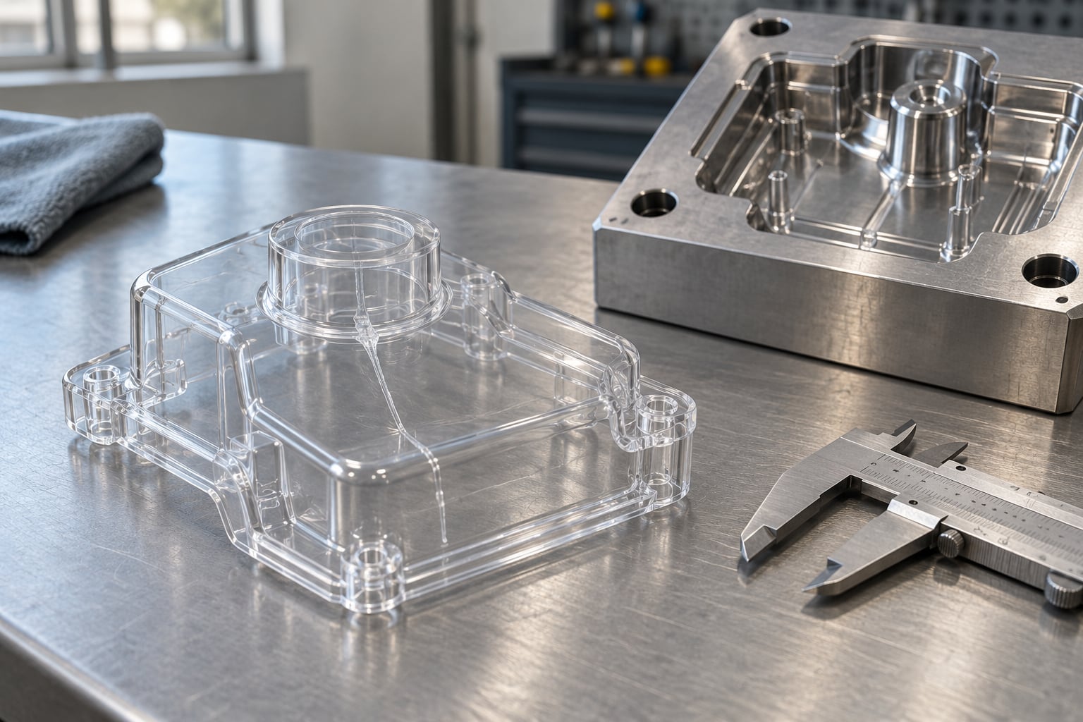
Jetting in injection molding shows up as a squiggly, worm-like streak that starts right at the gate and follows the first path the melt takes into the cavity. In most cases you can fix it without touching steel: the gate is almost always involved, and an injection speed that is too high for that gate is the other half of the problem. Below is the order I work through when a customer calls with a part that just started streaking.
The sequence matters more than the individual tricks. Diagnose the pattern, look at the gate, then change one flow-control variable at a time and prove it worked before moving on. If you change speed, melt temperature and mold temperature in the same trial you learn nothing, and you usually leave the part with a new defect instead of a fixed one.
Table of Contents
- What You Need
- Step-by-Step: How to Fix Jetting in Injection Molding
- Step 1: Confirm the Jetting Symptom and Its Location
- Step 2: Check Gate Size, Position, and Entry Angle
- Step 3: Reduce or Reshape the Initial Flow
- Step 4: Improve Mold Venting at the End of Fill
- Step 5: Review Mold Temperature and Cooling Conditions
- Step 6: Check Material Condition and Injection Unit Setup
- Step 7: Validate the Change With Controlled Trials
- Step 8: Lock the Correction into Production Controls
- Common Mistakes
- Frequently Asked Questions
- Conclusion
What You Need
Before touching a single setting, gather what you already have on site. Diagnosing jetting is mostly pattern recognition, and the data you pull together in the first ten minutes decides whether the answer lives on the machine or in the tool.
- Resin data. Grade, melt flow index, recommended melt temperature range, and whether the material is glass-filled. A filled resin and a clear homopolymer behave nothing alike at the same settings.
- Gate details from the drawing. Gate type, gate diameter or land dimensions, gate land length, entry angle into the cavity, and where the gate sits relative to the wall it feeds.
- The current process sheet. Barrel zone temperatures, melt temperature, mold temperatures per cavity half, injection speed profile, hold pressure, hold time, and cooling time.
- Fill pattern evidence. Run a short shot study by stopping the fill partway through so you can see how material actually travels, or examine a naturally short part from the start-up bin.
- Good inspection light. Raking light from a low angle, the kind that shows surface texture. Overhead fluorescent light hides a fine jet line completely.
- A known good part. One part from a previous run that passed inspection, if the defect is new. Comparing against it tells you whether the tool or the material lot changed.
- Notes on other defects. Whether flash, burn marks, short shots, weld lines, or sink marks are present in the same run. Several of them share a root cause with jetting.
If you do not have a process sheet, write the current settings down before you start. Half of the fixes below involve backing a value out later, and you need to know where you started.
Step-by-Step: How to Fix Jetting in Injection Molding
The eight steps below run in order because each one rules out a cause and hands you the next. Stop when the streak is gone and verify the part against your cosmetic standard before you continue, because a fix that only moves the streak to a different wall is not a fix.
Step 1: Confirm the Jetting Symptom and Its Location
Jetting has a signature: it begins at or very near the gate vestige and follows the first material path across the part. Look at the streak under raking light and trace it back. If it starts at the gate, you are almost certainly looking at jetting. If it starts where two flow fronts meet, that is a weld line, and no gate change will fix it.
Other defects get mistaken for jetting constantly. A flow line looks similar but forms when the fountain front pushes air ahead of itself without a free jet. Silver streaks that spread into a hazy patch near the end of fill are usually a venting problem. Bubbles look like shiny pits and come from moisture or trapped gas, not from a high-velocity stream.
One more thing to check: does the streak appear in every cavity, or only one? If only some cavities streak, the gate geometry is the same but the flow path length, wall thickness, or cooling balance differs between them. Also check whether the streak is in the same place on every shot. A consistent location points to tooling. A location that wanders points to the process or the material. Our guide to gate placement mistakes covers the geometry side in more depth.
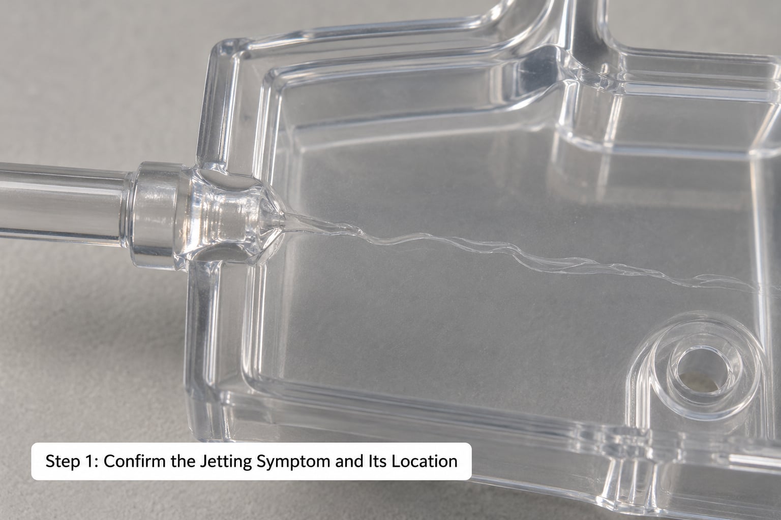
How to verify: you have a confirmed diagnosis when the streak starts at the gate, follows the initial flow path, and repeats at a consistent spot on the part.
Step 2: Check Gate Size, Position, and Entry Angle
A jet forms when melt leaves the gate as a narrow, free, fast-moving stream. Anything that makes that stream longer before it touches a wall makes jetting worse. A deep gate with a long land length turns the short flow path between runner and cavity into a high-velocity core that has time to fold back on itself.
Three geometry questions decide how much trouble your gate is causing. How large is the gate relative to the wall it feeds? A common rule of thumb is a gate diameter around 90 percent of the wall thickness, adjusted down for filled materials. Is the gate land length long? Land length is the distance the melt travels parallel to the mold surface after leaving the gate, and every extra millimeter of it adds to the whipping action. And where does the stream land? If it shoots across the cavity instead of driving straight into the wall, it has room to distort before it freezes.
Gate type matters here too. A fan gate or a ring gate spreads melt quickly and is far less prone to jetting than a small pinpoint or edge gate pointed into open space. A submarine gate that releases at the end of the run usually gives the cleanest cosmetic result on a flat panel. None of this can be changed in an afternoon, so measure it now and use it to decide whether you are buying time with process changes or going to the tool.
How to verify: compare the gate dimensions on the drawing against the wall thickness, and look at the direction the streak runs. A streak that curves and doubles back on itself matches a jet that travelled before it hit anything.
Step 3: Reduce or Reshape the Initial Flow
This is the cheapest fix and the one that resolves the largest share of cases, so it comes before any tooling decision. Injection speed at the moment the gate opens determines the velocity of that first stream. Cut the opening speed and the stream slows enough to start spreading against the wall before it folds.
What this looks like on the machine depends on the control. On a machine with multi-stage or profiled injection, set a slower first stage and let the fill rate ramp up only after the melt has contacted the far wall. A good starting point is to take the opening speed down by 20 to 30 percent from your current value and hold the fill long enough for the initial surge to settle. On a machine without profiling, slow the whole fill down and accept the longer cycle until the streak is controlled, then work the speed back up.
Back pressure on the screw is a secondary lever. A modest increase in back pressure during plasticization evens out the melt and can reduce pulsation, which shows up as an unsteady stream. It costs cycle time through a longer screw recovery, so use it only after speed profiling has been tried.
Do not reach for pressure first. Raising hold or injection pressure to fight a jet usually deforms the stream further and adds flash at the gate, because you are pushing harder through the same opening.
How to verify: run ten shots at the new speed and compare them against the current parts under the same lighting. The streak should shorten and start to hug the wall instead of curling away from it. If it just moved downstream, the speed was not the whole story.
Step 4: Improve Mold Venting at the End of Fill
Trapped air at the flow front distorts the melt stream and can create a streak that looks like jetting but originates at the end of fill rather than the gate. A part that is vented poorly will also show other symptoms together: burn marks around the last-filled section, flash that appears and disappears between shots, or a scratchy surface near the thickest area.
Check three things on the vent. Is it deep enough? Vents that are cut shallow or that have been partially blocked by a wear plate get starved. Where is it located? It should sit at the last point to fill, which is usually the end of the longest flow path or the thickest section. And is it big enough? A vent that is too small behaves like a partially closed valve and compresses the air instead of letting it out. Our guide to venting problems in injection molds covers the sizing details.
One caution: enlarging a vent to fix a jetting symptom can create flash. Go in small increments, clean the existing vent first, and re-check part weight and edge quality after each change.
How to verify: after cleaning or deepening the vent, watch the end of fill on a short shot part. Air should escape freely and the surface near the last-filled area should come out smooth. If jetting at the gate is unchanged, that is expected; venting was never the cause.
Step 5: Review Mold Temperature and Cooling Conditions
Melt that is too cold and mold steel that is too cold both make the window for jetting worse. A cold flow front has higher viscosity, so the free stream keeps its shape longer instead of spreading quickly against the wall. Colder melt also raises the shear rate at the gate for a given fill rate, and higher shear means more distortion of the surface layers.
Start by testing a controlled increase in mold temperature, typically in increments of 5 to 10 degrees Fahrenheit on the cavity side, and hold everything else constant. If the streak improves, keep the direction and continue in small steps until the part clears your cosmetic standard. A hotter mold also improves the surface finish of the filled area, so you may find you do not need as much speed reduction as you thought.
Melt temperature is the second lever. Raise it within the resin supplier’s recommended range rather than past it, since going beyond the specification costs cycle time through longer cooling and can degrade the resin. Check melt temperature with an air-shot pyrometer rather than trusting the barrel setpoints, which are usually optimistic.
Cooling around the gate deserves a look as well. If cooling lines run very close to the gate, the melt can start to freeze at the gate lip and eject in a ragged, uneven stream. Moving cooling lines away from the gate is tooling work, but knowing it is there tells you the process window will be narrow.
How to verify: change mold temperature in one direction and hold for a full steady-state cycle before judging, because the steel needs time to reach temperature. Then look for a shorter, softer streak at the gate and better gloss on the filled surface.
Step 6: Check Material Condition and Injection Unit Setup
Material problems show up as jetting more often than people expect. A wet resin produces bubbles and splay that can masquerade as a streak, and bubbles that break at the surface leave a pitted line. A resin that has been over-dried can turn brittle, and a contaminated hopper or a dirty screw head adds debris that disturbs the stream.
Check the drying setup against the resin specification: temperature, dew point, and time. Then check the actual melt with a purge and a filter screen inspection. If the screen is loaded, that changes your flow conditions whether you like it or not.
Regrind is a common trigger. A high regrind percentage, especially in a filled resin, raises the viscosity and the fibre content unevenly, and both make the initial stream less stable. Glass-filled nylon is a frequent offender because the fibres orient differently through a fast jet than they do in a packed flow, and the resulting surface reads as a visible streak. Many shops see the problem improve when they hold a defined regrind ratio rather than an informal one.
On the machine, check nozzle and sprue bushing alignment and the size of the nozzle orifice relative to the sprue. A restricted or misaligned nozzle makes the melt arrive at the sprue unevenly, and the cavity inherits that unevenness. If your machine has a check ring or non-return valve that is worn, decompression after injection changes too and you get a stream that starts and stops.
How to verify: after a drying correction or a resin change, watch the first few shots for a stable stream and take samples once the purge material has cleared. Compare them to parts from the previous lot under identical inspection conditions.
Step 7: Validate the Change With Controlled Trials
Controlled trials are what separate a fix from a coincidence. Change one factor, hold the rest, and take enough shots to see the steady state. The first shot off a new setting is almost never representative, because the mold is at a different temperature and the material has not equilibrated.
Run a small matrix rather than a long list. Speed at two levels, mold temperature at two levels, four combinations, ten shots each. That is forty parts and it will show you whether the two variables interact or whether one of them was doing all the work. Keep the same cavity position noted for every part, and record which cavity produced which shot, because cavity-to-cavity variation is real and it will hide a small improvement if you average it out.
Compare first-off parts against steady-state parts. Jetting that appears on first shots and fades is usually a mold temperature or material temperature effect. Jetting that is steady from the first shot to the last points squarely at gate geometry or injection speed.
Use a written acceptance limit. Define what counts as acceptable in the inspection standard, in writing, before you judge. Otherwise the argument about whether the streak improved becomes a matter of who is holding the part under the light.
How to verify: you have a fix when the streak meets your written standard on at least thirty consecutive shots, in more than one cavity, at steady state.
Step 8: Lock the Correction into Production Controls
A fix that lives in one operator’s head disappears at the next shift change. Write the final settings into the process sheet: gate condition, machine and tooling number, barrel zone temperatures, melt temperature, mold temperatures per cavity half, the full speed profile with each stage, hold pressure, hold time, cooling time, and the resin lot and drying conditions.
Update the control plan so first-article inspection looks for the jet line at the gate specifically, not just for cosmetic defects in general. Jetting tends to come back when someone raises the opening speed to recover cycle time, so a note explaining why that speed exists is worth more than the number itself.
Add the inspection point to the packaging or assembly instructions if the gate sits on a visible face. It is easier to reject a part at the bench with the gate under the light than at final inspection when the lot is already packed.
Finally, schedule the mold maintenance checks that protect the fix: gate and land condition, vent cleanliness, and water line scaling. A scaled cooling channel is the same as a colder mold, and you already know what a cold mold does to your streak. Our mold maintenance schedule guide lays out a practical interval for each check.
How to verify: a second operator can set the machine to the documented values and produce conforming parts without asking you a question.
Common Mistakes
Most jetting troubleshooting goes wrong in predictable ways. These are the ones I see repeatedly, and every one of them costs more time than doing it correctly the first time.
- Changing several variables in one trial. Adjusting speed, melt temperature and mold temperature together makes the result uninterpretable. If the part improves you still do not know which change did it, and the next time the defect returns you have three suspects instead of one.
- Rising pressure to push the streak out. More pressure through the same gate opening makes the stream faster, not slower. You usually gain flash and a heavier gate vestige along with the jet.
- Enlarging vents without watching for flash. A vent that is too large lets melt escape at the parting line, and on a cosmetic part that is a worse defect than the streak you were chasing. Clean the vent first, then increase depth in small steps.
- Polishing the gate before confirming flow direction. A shiny gate hides the vestige but does nothing about the velocity of the stream leaving it. Check the gate dimensions and entry angle first, since that is what determines whether jetting happens at all.
- Ignoring cavity-to-cavity variation. When only two of four cavities streak, the average result is misleading. Record every shot by cavity, and do not accept a fix that works in one cavity and fails in another.
- Treating flow lines, weld lines, and race track marks as jetting. Each has a different cause and a different fix. A race track, for instance, follows a wall of a different thickness and is fixed by a gate or thickness change, not by speed profiling. Our list of gate placement mistakes covers several defects that get confused with each other.
- Judging parts under the wrong light. Overhead light flattens surface texture and makes a light jet line look acceptable. Inspect with raking light from a low angle every time, and keep the inspection condition the same before and after each change.
- Skipping the short shot. Without a short shot part you are guessing at the fill pattern. A part filled to about 50 percent and one filled to about 75 percent show you where the melt went and where the air went, and that picture drives every decision that follows.
Two habits cut the number of trials in half: take a short shot part before you change anything, and keep a log. Six lines per trial, date, settings, result, is enough to stop repeating a change that already failed.
Frequently Asked Questions
Can jetting in injection molding be fixed without changing the mold?
In most cases, yes. Reducing the initial injection speed, profiling the fill in two stages, raising mold or melt temperature within the resin specification, and cleaning or deepening the vents resolve the majority of jetting without touching steel. Process changes alone work when the gate is large enough and directs melt into a wall. If the gate is small, has a long land length, or fires into open space, no setting will hold the fix, and gate work becomes the real answer.
What is the difference between jetting and flow lines?
Jetting starts at the gate. A free, high-velocity stream leaves the gate, travels without touching a wall, folds back on itself, and freezes into a squiggly worm pattern. A flow line forms when the fountain front pushes air ahead of it and the air disturbs the surface, so it appears along the flow path rather than at the gate. Fixing a flow line usually means venting and speed; fixing jetting usually means the gate and the opening speed.
What gate design prevents jetting?
Wide, shallow gates that feed melt straight into the wall are the reliable answer. Fan gates and ring gates spread flow quickly, submarine gates release at the end of the run and keep the vestige off the visible face, and edge gates work when they point into the wall rather than across the cavity. A common sizing rule is a gate diameter near 90 percent of the wall thickness, reduced for glass-filled materials. Long gate land lengths are the most common geometry mistake that produces jetting.
How does injection speed cause jetting?
Speed at the moment the gate opens sets the velocity of the first melt stream. A high opening speed lets that stream travel further before it contacts a wall, and the faster it moves the less time it has to spread and adhere. Lower the opening speed or use a two-stage profile with a slow start, then increase the rate once the melt has reached the far wall. Higher pressure at the same speed makes the distortion worse, not better.
Is jetting only a cosmetic defect?
It is mostly cosmetic, but not entirely. The folded polymer layers in a jet line do not fuse to the same degree as the surrounding material, so the streak can act as a weak line in a structural part or a stress concentrator under load. On Class A surface programs and consumer-facing parts, it is a direct cause of cosmetic rejects and first-article failures. Because it shows up right at the gate, it tends to land on the most visible face of the part.
Conclusion
Start with the pattern, not the settings. Confirm that the streak begins at the gate and repeats in the same place, take a short shot part so you can see how the melt actually travels, and measure the gate against the wall it feeds. Then change one thing: cut the opening speed first, since it resolves the largest share of cases for the least effort. If that does not clear it, work through venting, then mold and melt temperature, then material condition. Document the setting that finally held, put it on the process sheet, and add a gate-area check to first-article inspection so the streak does not come back on the next shift.