
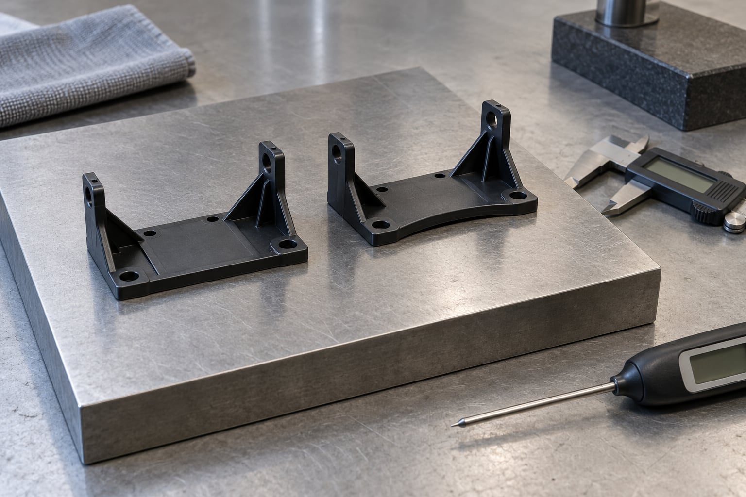
Warping in injection molded parts comes down to one thing: different areas of the part cool and shrink at different rates, and the mismatch leaves residual stress that bends the part after ejection. To fix it, work through the causes in order — measure the defect, check material and mold temperature, then gate, packing, cooling and geometry — and change one variable at a time. Most warpage is corrected with a machine setting or a cooling adjustment, done the same day. Cases driven by wall thickness or fiber orientation need tooling work or a material change.
The frustrating part is that warpage rarely has a single cause. Two or three contributors usually stack up, which is why the shotgun fix of cranking up pressure and cooling time often hides the problem for a week and then brings it back. Diagnose first, adjust second, measure third.
Table of Contents
- What You Need
- Step-by-Step: How to Fix Warping in Injection Molded Parts
- Step 1: Confirm the Warping Pattern and Measure the Parts
- Step 2: Check Resin, Drying, and Material Handling
- Step 3: Review Mold Temperature and Cooling Balance
- Step 4: Correct Gate Placement, Filling, and Packing
- Step 5: Improve Part and Mold Design to Stop Warping
- Step 6: Validate the Correction and Control Production Drift
- Common Mistakes
- Frequently Asked Questions
- Can warped injection molded parts be fixed without changing the mold?
- What is the most common cause of warping in injection molded parts?
- Does increasing mold cooling time always reduce warping?
- How can I tell the difference between warping and sink marks?
- Should I change the resin or adjust the molding process first?
- How do I stop warped parts from failing dimensional inspection?
- Conclusion
What You Need
Before you touch a setting, gather the evidence. This is a short list and every item on it answers a question you would otherwise be guessing at.
- Affected part samples — pull parts from several cavities and several cycles, not one handful off the belt. Warping that only shows in cavity 3 of a four-cavity tool is a mold-flow clue in itself.
- A flat surface and a set of feeler gauges — a granite plate or a surface plate turns “looks bent” into a number. Sliding the part against the plate and measuring the gap at the high point gives you a repeatable baseline.
- Dimensional inspection equipment — at minimum a dial indicator for out-of-flat and critical dimensions; a coordinate measuring machine when the part has tight flatness callouts.
- Molding records — cycle time, cooling time, melt and mold temperature, injection and holding pressure, fill and pack times, back pressure, decompression, and the exact settings used on good parts versus bad ones.
- Material and drying data — resin grade, lot number, dryer temperature and dwell time, moisture readings, regrind percentage, and how long the hopper has been running.
- Mold-temperature data — water in and out temperatures at the core and near the cavity surface, flow rate, and measured cavity temperatures by zone rather than the machine setpoint alone.
- Part and mold geometry — the drawing wall thickness map and the cavity layout: gate position, runner balance, rib thickness and height, boss placement, and cooling channel layout.
Step-by-Step: How to Fix Warping in Injection Molded Parts
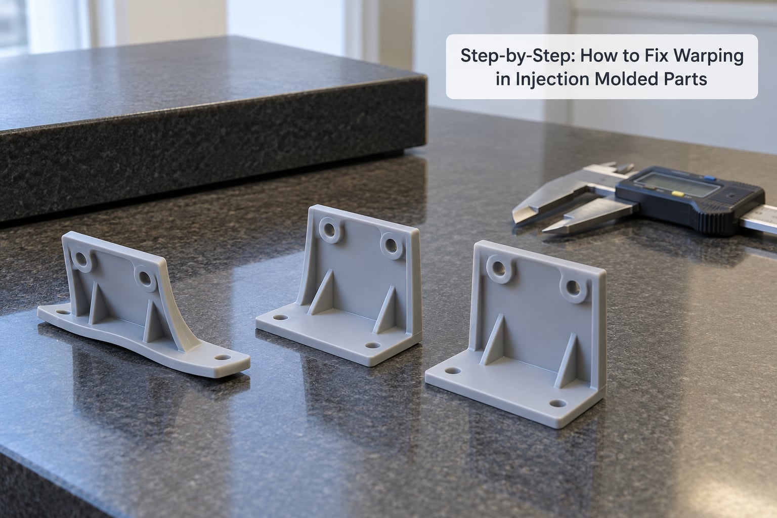
The order matters. Each step rules something in or out, so you do not spend a trial chasing the wrong system.
Step 1: Confirm the Warping Pattern and Measure the Parts
Bowing, twisting, cupping, rib-following warp and gate-area distortion all point at different causes, so name the shape before you name a fix. Set the part on a flat plate and check whether the bow runs along the long axis, across it, or twists diagonally. Twist usually means asymmetric shrinkage or unbalanced ejection. Cupping toward the gate suggests the gate region is shrinking more than the far end.
Then record numbers: maximum deviation from the datum plane, and the deviation location relative to the gate, ribs and bosses. Compare parts from every cavity and several cycles. Validation criterion: you have a written pattern — which cavities, which zones, how many millimeters — before you change anything.
If you want the measurement side documented properly, the CMM inspection basics for plastic parts guide covers flatness callouts and how to report them.
Step 2: Check Resin, Drying, and Material Handling
Moisture in hygroscopic resins turns the melt into a foam, and foamed melt shrinks erratically. Contamination from a dusty dryer, a dirty hopper, or a purge compound left from the previous material does similar damage. So does a resin lot with a different filler level or a regrind ratio that drifted upward without anyone updating the process sheet.
Check three things. Read the dryer log and confirm actual dew point and material temperature, not just that the dryer was switched on. Take a sample and run a moisture test if your material data sheet calls for it. Confirm the regrind percentage and that the hopper has been purged correctly after a material change.
Validation criterion: the same lot, dried to the datasheet moisture target, with a recorded regrind percentage, and warpage still present. Only then is material excluded as the driver.
Step 3: Review Mold Temperature and Cooling Balance
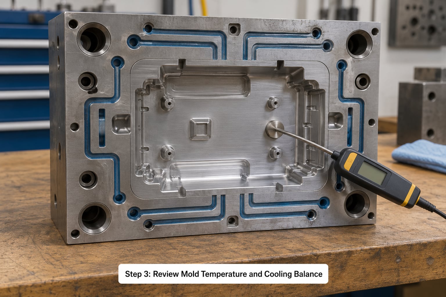
Unbalanced cooling is the most common cause of warping in injection molding, and it is the first place I look. The machine setpoint is not the cavity temperature. Measure the actual cavity face temperature at the hot end, the cold end and the middle, and compare them.
The numbers worth holding in your head: aim for a mold temperature spread across the cavity of no more than about plus or minus 5C, keep channel center-to-center spacing at roughly 3 to 5 times channel diameter, and hold the channel surface distance at about 1.5 to 2.5 times diameter. Design water lines for a Reynolds number above 4000 so you get turbulent rather than laminar flow, and add a 10 to 20 percent buffer on top of theoretical cooling time rather than running to the calculated minimum.
Series flow guarantees a temperature difference between the first and last channel. Parallel circuits equalize it, at the cost of bigger pumps and more loops. If one region is stubbornly hot, look for a hot spot between channels or a core pin with no cooling at all.
Our mold temperature control best practices reference covers controller accuracy, water-side temperature and seasonal stability in more depth.
Validation criterion: a coolant delta between in and out of a few degrees, measured cavity temperatures within the spread target, and consistent cooling from cycle to cycle.
Step 4: Correct Gate Placement, Filling, and Packing
Gate position sets the fill pattern, and the fill pattern sets the shrinkage pattern. A gate on one end of a long flat panel means that end packs denser and shrinks more. Reorienting or re-balancing the runner is a mold change; before you go there, tune what the machine can do.
- Injection speed — a slower fill reduces frozen-in orientation stress, which matters in long, thin parts. Going faster improves weld line strength. There is a balance, and it is part-specific.
- Melt temperature — higher melt temperature reduces viscosity and orientation stress but adds cycle time and can raise the risk of surface defects.
- Holding pressure and time — reduce packing when the gate region over-shrinks relative to the far end. Gate-side warping often disappears when you lower holding pressure rather than raise it.
- Back pressure — modest back pressure homogenizes the melt and improves filler and fiber distribution in reinforced grades.
- Decompression — excessive decompression lets the part spring back; too little causes surface marks and machine wear.
Warnings: moving a gate or rebalancing a runner needs tooling work and a fresh trial. Raising holding pressure across the board is not a fix — it packs in more stress and can make warping worse. Validation criterion: one parameter changed per trial, with deviation numbers from Step 1 recorded for each run.
Step 5: Improve Part and Mold Design to Stop Warping
Some warpage cannot be tuned out. When the cause is geometry, more pressure and more cooling time just buy you a slower cycle and a straighter part that is still out of tolerance.
- Uniform wall thickness — every thick region shrinks more and shrinks longer. Core out solid sections or use cored ribs rather than adding steel.
- Ribs at 50 to 60 percent of nominal wall — a rib at full wall thickness is a sink generator and a new source of differential shrinkage.
- Even distribution — put ribs and bosses on a consistent pitch and keep them off the parting line where possible.
- Filleted transitions — sharp steps from thick to thin concentrate both stress and cooling differences.
- Ejection balance — imbalanced ejector pins push the part sideways as it leaves. Add pins, redistribute them, add air assist, and confirm draft on every surface that grips.
- Gate orientation for reinforced grades — in glass-filled parts, flow direction sets fiber orientation, and fibers shrink far less along their length than across it. Anisotropic shrinkage in fiber-reinforced resins is the reason a reinforced housing curls away from the flow direction even with perfect cooling.
Validation criterion: a Moldflow or Moldex3D warpage study that names the dominant contributor, so tooling spend targets the real cause instead of the loudest symptom. Sink-prone regions are worth diagnosing separately, and the guide to what causes sink marks in injection molded parts separates that defect from warpage clearly.
Step 6: Validate the Correction and Control Production Drift
Set acceptance criteria before the trial run: a maximum out-of-flat figure, the critical dimensions that must hold, and the sample plan. Then run a controlled trial and pull samples from every cavity across multiple cycles, not just the first ten shots after the change settles.
Record the full process state with each sample — lot, regrind ratio, dryer log, mold temperature by zone, fill time, packing time, coolant in/out temperatures, ejection temperature and cycle number. That record is what lets you find drift later instead of guessing at it.
Two things cause warpage to return months later without anything changing in the process sheet: seasonal cooling loop and condensation in the water lines, and resin lots arriving with different filler levels or melt flow rate. Seasonal checks on coolant temperature and controller stability, plus a lot-change verification run, close both.
Validation criterion: every sampled cavity meets the out-of-flat tolerance across consecutive cycles, with no cavity averaging worse than the others.
Common Mistakes
- Raising pressure without checking flow. More holding pressure on an unbalanced fill adds stress rather than removing it. Correct: map the fill pattern and fix the gate and runner balance first.
- Treating every warping problem as a material problem. Changing resin lots when the cooling circuit is the culprit costs money and hides the cause. Correct: measure cavity temperatures before blaming the material.
- Changing several variables at once. You learn nothing and cannot repeat the result. Correct: one parameter per trial, recorded.
- Measuring only one cavity. A tool with uneven cooling produces a mix of good and bad parts, so the average hides the problem. Correct: sample every cavity and every cycle.
- Cooling parts unevenly after ejection. Stacking warm flat panels on a flat surface bakes in the curve. Correct: cool under constraint or space parts so air reaches both faces evenly.
- Ignoring post-molding handling. Parts stacked hot pick up stress from their neighbors. Correct: rack parts with clearance and let them reach a stable temperature before packing.
- Never defining what acceptable warpage is. Without an out-of-flat tolerance, nobody can say whether the fix worked. Correct: write the tolerance into the drawing before you start.
Prevention is mostly boring and mostly effective: hold uniform wall thickness, keep cooling balanced, keep the mold clean and polished, and document the process state with every lot change.
Frequently Asked Questions
Can warped injection molded parts be fixed without changing the mold?
Usually yes, when the cause is process related. Better cooling balance, more cooling time with a 10 to 20 percent buffer, staged holding pressure, and a revised fill pattern correct most warping caused by differential shrinkage from uneven cooling. Mold changes are needed when the cause is non-uniform wall thickness, unsupported features, imbalanced gate and runner layout, or fiber orientation set by the flow path. Diagnose first with measured cavity temperatures and dimensional data, then decide.
What is the most common cause of warping in injection molded parts?
Uneven cooling is the most common cause, followed closely by non-uniform wall thickness and imbalanced packing. Where one region of a part stays molten longer, it keeps shrinking after the surrounding area has already set, and that restrained shrinkage becomes residual stress and a curve or twist. Field reports from molding engineers put the cooling circuit at the top of the list for good reason: it is measurable, and it is where most fixes land.
Does increasing mold cooling time always reduce warping?
No. Extra cooling time only helps when the part is genuinely leaving the mold too hot, and it costs cycle time on every shot. If warping comes from thick sections, gate-side overpacking, or fiber orientation, longer cooling may flatten nothing while making the part more brittle and slower to run. Raise cooling time in increments and measure out-of-flat each time, and check the cavity temperature spread across zones so you know whether cooling is uneven before you extend the dwell.
How can I tell the difference between warping and sink marks?
A sink mark is a local depression, usually on the back side of a wall opposite a thick rib or boss. Warpage is a change in overall geometry, a bow, twist or cup across the whole part. Sink depth usually measures against the local wall surface, while warpage is judged as out-of-flat against a datum plane. Parts often have both, and the fixes overlap only partly, so identify which one is out of tolerance first.
Should I change the resin or adjust the molding process first?
Adjust the process first in almost every case. Process settings are free to change and reversible in minutes, while a resin change needs a new process sheet, a trial, and possibly a dryer and purge cycle. Verify drying and regrind ratio first, since moisture and contamination change shrinkage behavior on their own. Move to a lower-shrinkage or lower-fiber grade only after the cooling circuit, gate layout and wall thickness have been ruled out.
How do I stop warped parts from failing dimensional inspection?
Define the out-of-flat tolerance on the drawing, then measure the same way every time — a surface plate with feeler gauges for a quick check, a dial indicator for critical dimensions, or a CMM for reporting. Sample every cavity across several cycles instead of a single part, and record the process state alongside each measurement. Once you have that record, you can tell a real correction from a good run that happened by luck.
Conclusion
The reliable way to fix warping in injection molded parts is to diagnose in order rather than adjust at random. Measure the pattern and the deviation first, confirm material condition and measured mold temperatures next, then work through gate and fill, packing, cooling and geometry, changing one variable per trial.
Do this on day one: put the part on a flat plate and record the deviation in millimeters, check the dryer log and regrind ratio, and measure cavity temperatures across zones. Then make one controlled change and validate it across every cavity and several cycles before you call it fixed.