
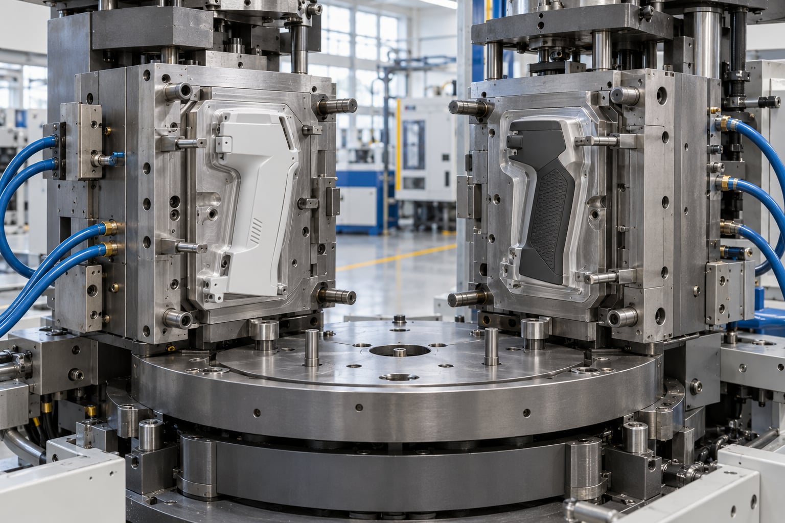
Multi shot injection molding explained in one line: it is a molding process where two or more plastic materials are injected into the same tool in sequence during a single machine cycle, and the part comes out finished rather than assembled later. A rotary platen or a sliding core moves the mold between injections so the second material lands on the first one while both are still hot. If you are designing a grip, a housing, a seal or a handheld product, this is the process that decides whether you pay for a separate soft-touch overmolding step or fold it into one shot.
The rest of this guide walks through the machine, the cycle, the design rules and the failure modes, so you can talk to a molder with specifics instead of nodding along.
Table of Contents
- What Is Multi Shot Injection Molding?
- How Does Multi Shot Injection Molding Work?
- What Are the Main Types of Multi Shot Systems?
- What Is the Multi Shot Injection Molding Process?
- How Does Multi Shot Injection Molding Explained Fit Into Design for Manufacturing?
- What Materials and Products Are Best Suited?
- What Are the Advantages and Limitations?
- How Do You Control Quality and Prevent Defects?
- Frequently Asked Questions
- Is two-shot injection molding the same as multi-shot injection molding?
- What determines the cost of a multi-shot injection molding tool?
- How many materials can be used in one multi-shot molding cycle?
- Can multi-shot molding create different colors or surface textures?
- What causes poor bonding between shots in multi-shot molding?
- Conclusion
What Is Multi Shot Injection Molding?
Multi shot injection molding is the injection molding of two or more materials in one machine cycle, in a defined sequence, so the finished part leaves the tool complete. The first material forms the structural body of the part. The mold then indexes or rotates, and the second material is injected onto the surface of the first one, where it bonds before cooling.
The key requirement is multiple molding stations or multiple material feeds feeding one part. That means a second injection unit, a hot runner or secondary nozzle, and a way to move the tool between shots. It also means both materials must be able to coexist: chemically compatible enough to bond, and physically able to handle the heat the other one brings.
The naming gets loose in conversation. Two-shot molding and 2K molding usually mean the two-material version. Multi-shot means anything beyond two, including three-shot parts with a core, a body and a soft overmold. All of them fall under multi-material injection molding. When you ask a supplier for a quote, say how many shots you need rather than which synonym you prefer, because some shops only stock two-station tooling.
How multi shot molding differs from the alternatives
Overmolding is the loose word people use for putting a soft material over a hard one. In industry usage, overmolding usually describes a separate secondary process: the hard part is molded first on a single-cavity machine, then a robot or operator places it into a second tool for the soft shot. Multi shot molding is different because both shots happen inside one tool, in one cycle, without a handling step between them.
Insert molding also produces a multi-material part, but the extra material is a rigid insert, not a soft skin. The insert is loaded into the mold before the cycle and encapsulated by the melt. It is the right answer when you need a metal screw, a threaded bushing or an electronic component inside the plastic, and the wrong answer when you want grip, sealing or vibration damping.
| Process | Shots per cycle | Tool moves between shots | Typical result |
|---|---|---|---|
| Standard molding | One | No | Single-material part |
| Multi shot molding | Two to four or more | Yes, rotary platen or sliding core | Bonded hard and soft part, no assembly |
| Secondary overmolding | One, in a second operation | Part is removed and re-located | Soft skin, but with a handling and registration step |
| Insert molding | One | No | Rigid insert encapsulated in plastic |
So multi shot injection molding explained means the multi-material part is made in one cycle inside one tool. That single-cycle difference is where the cost and cycle-time arguments come from.
How Does Multi Shot Injection Molding Work?
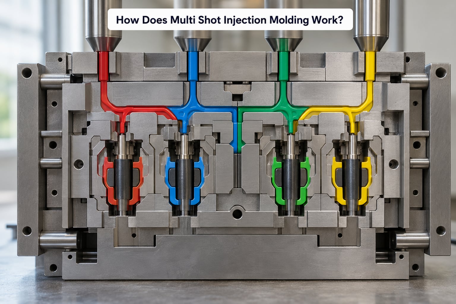
Picture a toothbrush handle. The rigid body comes first. After that shot fills and cools just enough to hold its shape, the mold indexes, a soft elastomer gate lines up over the handle, and the second material wraps around it. The tool closes again, both halves cool, and the part is ejected as a single piece with the grip already bonded on.
Step one is the first injection. The machine’s main screw melts the rigid polymer, usually something like polypropylene, polycarbonate or ABS, and injects it through the cold runner into the cavity. Because this material defines the part’s geometry, it gets the full attention on gate location, fill pattern and cooling.
Step two is the index or rotation. A rotary platen turns the mold half a full 180 degrees, or a sliding core shifts along a rail, or an index plate moves the cavity to a different station. Whatever moves, the effect is the same: the first shot’s geometry is now presented as the target for the second material, and the mold remains closed so nothing shifts.
Step three is the second injection. A second screw or a valve-gated hot runner delivers the second material onto the still-warm first material. Because the substrate has not fully cooled, the two melts interdiffuse at the interface over the contact time available. This is the bond, and it is the entire reason the process works. Get it right and the interface is stronger than either material alone in a pull test.
Step four is cooling and ejection. Both materials cool together while still indexed or rotated, then the tool opens and ejectors push the part out. The part is complete on the first cycle that produces it, with no secondary operation, no glue, no ultrasonic weld and no fixture to hold alignment.
Timing is the whole game. Too fast and the second melt hits a substrate that has already frozen, giving you a poor bond. Too slow and the substrate overheats or the cycle drags. Mold rotation is usually indexed in a fraction of the total cycle, and the molders who run these tools well adjust that index position the way a chef adjusts a heat setting.
What Are the Main Types of Multi Shot Systems?
There are four machine architectures you will run into, and the right one usually follows from the part shape and the annual volume.
| System | How it indexes | Best fit | Watch out for |
|---|---|---|---|
| Rotary platen | Platen turns 180 degrees between shots | Common two-shot parts, housings, grips | Platen size limits part size and shot weight |
| Core rotation | Mold core rotates on a vertical axis | Round parts, cups, wheels, circular grips | Radial flow lines and concentric cooling |
| Index plate | Cavities move on a plate to fixed stations | Multi-cavity, three or four shot parts | Balance across every station, harder to vent |
| Shuttle or transfer tool | Tool halves move to load and mold positions | Large panels and bulky parts | Ties up machine time during transfer |
The rotary platen is the arrangement most buyers picture, and it is the most widely available. It is also the least flexible once the tool is built, because the station positions are fixed into the platen layout. When you need a third or fourth shot, an index plate gives you more stations but demands careful process work to keep every station balanced.
Sandwich molding sits alongside these. Instead of one material over another, a thin core layer is injected between two outer layers in one go. Different gating paths let it fill completely before the next material arrives. It gives you a softer, better-insulating core with a cosmetic surface on both sides, at the cost of very demanding process control.
Pick the system by asking four questions in order: does the part geometry allow the mold to move without the part moving with it, do the materials bond on their own or need a mechanical interlock, how many cavities do you need at annual volume, and what does the machine’s platen and tie-bar clearance allow. Get those four answers and the machine choice usually makes itself.
What Is the Multi Shot Injection Molding Process?
The production sequence has more steps than a single-shot run, and the order matters. This is the sequence from an empty crate of resin to a boxed part.
- Mold preparation and incoming inspection. Before the first shot, check the shut-off surfaces for flash damage, confirm core alignment within the tolerances the rotary platen requires, and verify cooling channel flow is balanced across both stations. Fractions of a millimeter of platen misalignment show up as flash you cannot fix with process settings.
- Material drying and blending. Thermoplastic elastomers are hygroscopic and pick up moisture from the air. Wet material causes splay marks, flow lines and bubbles at the interface. Dry to the resin manufacturer’s specification, keep the hopper and dryer in a controlled area, and weigh every batch.
- Purge and first-shot filling. Run the rigid material alone until the cavity is full and the part dimensions are stable. Confirm the critical dimensions on a first article against the drawing before you let the second material anywhere near it.
- Interface preparation at the substrate. The surface receiving the soft shot has to be clean, warm and free of release agent or mold texturing compound. Any contamination in that zone becomes a delamination risk later.
- Station changeover. The mold rotates, the core shifts or the index plate moves. The control system interlocks so the second injection cannot fire before the index position is confirmed at the correct rotational position.
- Subsequent-shot molding. The second, and any further, material is injected onto the substrate. Hold pressure, back pressure and melt temperature in the window the supplier specifies for that grade pairing, because those settings are specific to the combination, not to the machine.
- Cooling. Cool with both parts still indexed so the bond can finish setting under the correct geometry. Uneven cooling here is the usual root of a curl or twist that shows up a week later in the customer’s hand.
- Ejection and handling. Eject on the rigid body rather than the soft material, and use the parting line as the grab point. Overmolded parts get damaged in handling more often than they get molded wrong.
- Inspection and process control. Check the interface for bond strength, verify cosmetic surfaces, measure key dimensions and log results. SPC charts for injection molding explained in our guide show how to turn those readings into trends rather than one-off pass or fail calls.
Between steps, the process window is tightest at the interface. A molder who has never run your specific grade pairing will spend trial time there, which is exactly why pilot runs and honest defect data matter when you choose a supplier.
How Does Multi Shot Injection Molding Explained Fit Into Design for Manufacturing?
Most multi shot problems start as design decisions, long before anyone sets a melt temperature. Here are the rules that matter most.
Choose the shot sequence deliberately
Decide which material goes in first based on geometry, not on cost. Usually the rigid body goes first because it defines the parting line and takes the sharpest features, and the soft material goes second because it can flow over gentle curves. If your soft layer needs to wrap into a sharp inside corner, reverse the sequence or add a radius. The soft material cannot make a corner the rigid shell already refused to fill.
Plan gates for both materials
Each material needs its own gate, positioned where the flow stays balanced and away from the bond line if possible. A second gate that lands in the middle of the soft feature creates a visible weld line and a thin spot. Our guide to gate placement mistakes to avoid in injection molding covers the classic positioning errors that carry straight into multi shot work.
Account for shrinkage and thermal mismatch
The rigid body shrinks as it cools and is already rigid when the soft shot arrives. Give the second material enough room to take up the difference instead of compressing it, or you will see the soft layer squeeze out at the shut-off. Where the two materials have very different coefficients of thermal expansion, the interface will be loaded the whole time the part cools. Uniform wall thickness keeps that load even.
Build a real shut-off
Use crush ribs on the shut-off surface. They deflect slightly at closing so they seal without dragging, and they give the elastomer a consistent edge to shrink against. A flat, over-tight shut-off is how you end up chasing flash. Our piece on how to prevent flash in injection molding has the process-side fixes.
Avoid unsupported walls and trapped geometry
Unsupported sections spanning the index position can flex when the mold moves. Keep continuous support on the rigid side, avoid deep pockets on the substrate face, and vent the second station properly. trapped air in the soft station reads as a short shot that no amount of pressure will fix.
Decide early whether inserts are even relevant
If the part needs a metal insert and a soft grip, decide whether you need insert molding, multi shot molding, or a third process entirely. Combining all of them in one tool is possible but pushes cycle time and cost hard, and few shops run it well.
What Materials and Products Are Best Suited?
Multi shot injection molding explained simply comes down to chemistry: a polar rigid material bonds readily to a soft TPE, while non-polar combinations need mechanical interlock or a tie layer to hold together.
| Rigid substrate | Typical soft material | Bond behavior | Common parts |
|---|---|---|---|
| Polypropylene | SEBS-based TPE | Bonds well; PP over PP also fuses naturally | Handles, clippers, containers |
| ABS | TPE with a compatible grade | Bond strength depends heavily on grade selection | Consumer grips, small housings |
| Polycarbonate | TPE or silicone | Good with the right grade; watch for stress whitening | Medical devices, handheld tools |
| Nylon | TPE, usually a co-molded elastomer | Good in matched PA systems | Automotive interior trim, connectors |
| Thermoset-like soft | TPU or LSR | LSR needs hot runner and closed tooling | Seals, soft-touch panels |
On the product side, the pattern is consistent: a part that needs grip, sealing, vibration damping or a soft touch while keeping a rigid, dimensionally stable core. Power tool handles and trigger guards are textbook cases. So are toothbrush handles, shaver grips, remote control buttons and keycaps, electronic housings with integrated seals, bicycle and fitness equipment grips, automotive interior switchgear and dashboard trim, and medical device bodies where a compliant grip sits on a rigid frame.
Packaging is growing here too, especially closures and dispensing components where a compliant sealing lip is molded directly onto a rigid closure. The practical test is simple: if a soft touch, a seal or a shock-absorbing layer sits on a rigid part, multi shot is usually the process the part was designed around.
What Are the Advantages and Limitations?
The advantages are real and mostly economic. You remove a whole secondary operation, along with its fixtures, operators, cycle time and scrap. Parts arrive at assembly complete. The bond between materials is molecular where chemistry allows it, so the interface holds up under pull, torsion and vibration better than an adhesive joint on a smooth plastic surface. Multi shot parts also look better, because there is no seam where a soft skin butts against a hard core, and repeatability is high once the process is stable.
The limitations matter just as much. Tooling costs several times what a single-cavity single-shot tool costs, because every station needs its own gating, cooling and venting. Cycle time goes up with every shot, since you fill, cool and index between materials. The machine has to be big enough for both shots and stable enough for the platen, and that narrows which shops can quote your part. Recycling gets harder with each material added, since separating a bonded elastomer from a rigid body is not simple. And a multi-material part cannot be re-melted as a single resin stream, which rules the approach out for some recycled-content programs.
How volume changes the economics
The math that decides whether multi shot is worth it is amortized tooling. Buyers on shop forums keep landing on the same wall: a custom multi-shot tool is a real capital outlay, and at a couple of thousand parts a year that cost never disappears. Two thousand to five thousand units a year is the awkward zone where tooling dominates unit cost, and a well-run shop will say so plainly rather than quote you a piece price that quietly assumes a much larger run.
Ask for the tool amortized over a specific volume, in writing, and ask what the piece price looks like at your actual run size and at ten times that. If a supplier will not discuss amortization, you are comparing quotes that were never built on the same assumptions.
One more practical limit: change control
A revision that is trivial on a single-shot tool can force new core work when a second material is in the mix, because a dimension change on the rigid body changes where the soft material lands. Freeze the soft feature early or budget for a second tool revision.
How Do You Control Quality and Prevent Defects?
Multi shot defects fall into two groups. One comes from the process, the other from the interface between materials. Work the symptom, not the guess.
| Symptom | Usual cause | Where to act |
|---|---|---|
| Short shot on the soft material | Trapped air, premature freeze, low melt temperature | Improve venting at the soft station, raise melt temperature, extend the substrate’s residual heat |
| Delamination or peeling | Substrate too cold, contamination, incompatible grades, moisture | Dry resin, clean the substrate face, index sooner, switch to a bonding grade |
| Flash at the shut-off | Crush rib too aggressive or worn, platen misalignment, overpacking | Rebuild the shut-off, verify core alignment, reduce hold pressure in small steps |
| Sink marks | Thick section, too much material in one station | Reduce wall thickness, add cooling, redistribute flow with a gate change |
| Warpage or curl | Uneven cooling, thermal mismatch, uneven wall thickness | Balance cooling circuits, even out wall thickness, allow longer cooling before ejection |
| Flow marks or gate blush | High shear at the gate, cold mold, moisture in the melt | Raise gate size or mold temperature, dry thoroughly, lower injection speed |
| Burn marks or soot | Trapped air igniting at the end of fill | Vent the end of fill, slow the last part of the stroke, check melt temperature |
| Dimensional drift across shots | Index position variation, inconsistent material temperature | Calibrate rotation hydraulics and mechanical stops, log melt temperature per shot |
Two habits catch most of these early. First, log bond strength on a defined schedule rather than trusting a visual check, because a bond that looks fine can still be weak. Second, log the index position and the time between shots, since the interface bond depends on the substrate still being warm when the second material lands.
Before signing a supplier, ask whether they run the equipment in-house, who built the tool, whether they will give DFM feedback before steel is cut, whether they will run a pilot before the production commitment, and whether they can show defect rate data with a corrective action process. Molders who dodge those answers usually push their own tooling instead of accepting yours, and the accountability gap when a defect appears is exactly where projects stall.
Frequently Asked Questions
Is two-shot injection molding the same as multi-shot injection molding?
Two-shot molding is the two-material case of multi-shot injection molding, so in practice the terms are used interchangeably when a part has a rigid core and a soft overmold. Multi-shot is the broader term and covers three, four or more shots on an index plate or core-rotation tool. When you request a quote, state the number of shots and the material stack rather than relying on the label.
What determines the cost of a multi-shot injection molding tool?
Tool cost tracks the number of stations, cavity count and mold complexity. Each added shot needs its own gating, cooling and venting, and a rotary or index mechanism adds alignment and machining work. A single-cavity two-shot tool typically runs into five figures, and multi-cavity or multi-station tools climb well past that. Annual volume is the biggest lever on piece price, because the same tool amortizes across more parts.
How many materials can be used in one multi-shot molding cycle?
Two to four materials per cycle is normal practice, with index plates handling three or four stations and complex tools occasionally going further. Each additional shot adds cycle time, tooling cost and a new interface to bond, so the practical limit is usually economics rather than machine capability. More materials also complicate recycling, since a bonded multi-material part cannot be re-melted as a single resin stream.
Can multi-shot molding create different colors or surface textures?
Yes. Different colors are simply different materials or color concentrates in separate stations, and texture comes from the cavity surface at each station, so a matte soft grip over a gloss rigid body needs no secondary finishing. Color changeover means purging the relevant barrel and hot runner, which costs time on short runs. Multi-color parts also hide parting lines well, which is one reason the process suits cosmetic consumer products.
What causes poor bonding between shots in multi-shot molding?
Most bonding failures trace to a substrate that has cooled too far before the second material arrives, moisture in the hygroscopic soft resin, contamination or release agent left on the substrate face, or a grade pairing that does not bond without a mechanical interlock. Moving the index position earlier, drying resin properly and cleaning the interface zone fix most cases. If chemistry is the issue, a bonding grade or a designed interlock is the fix.
Conclusion
Multi shot injection molding explained comes down to five decisions made before anyone cuts steel: which materials stack on which, what surface finish each station needs, the order the shots run in, whether the geometry lets the mold index without dragging the part, and your real annual volume. Write those down and any molder can quote you a process and a piece price in one conversation instead of three rounds of email.