
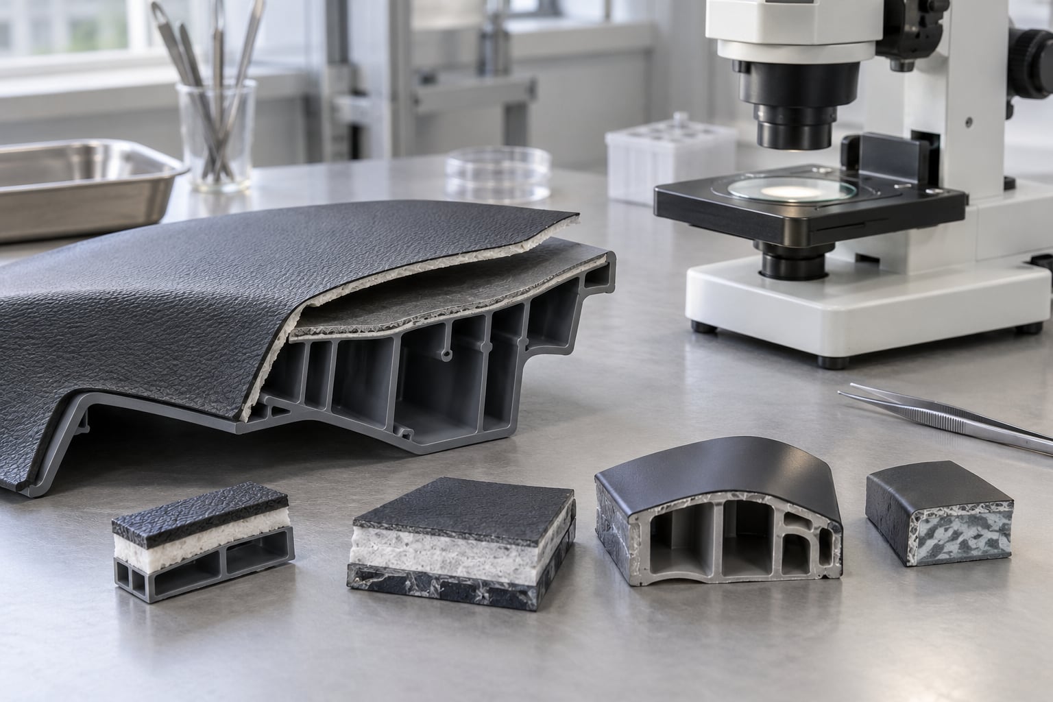
Delamination in molded parts is the separation of a thin surface skin or an internal layer from the body of the part, caused by a bond that never formed, formed weakly, or failed later in service. It shows up as a peelable skin, a lifting edge, a crack that follows a layer, or a hollow sound under a sectioned part. In most plants it is not a cosmetic complaint — it means a weak plane is sitting inside a part that was sold as solid, and it will usually surface weeks later at the customer.
So what causes delamination in molded parts? Nine families do almost all of the damage: contamination, moisture, gas, mold release residue, incompatible regrind, poor pigment or filler dispersion, process settings that freeze layers before they fuse, geometry that starves fusion, and aging that attacks a marginal interface. This guide walks the symptom back to the cause, then gives you the check that confirms it.
If you are new to this defect, start with the definition table below and the cause matrix a few sections down. If you already have parts failing in front of you, jump to the confirmation section and work backwards from where the delamination sits on the part.
Table of Contents
- What Is Delamination in a Molded Plastic Part?
- Delamination in Molded Parts Causes: Material and Design Failures
- What Causes Delamination in Molded Parts During Molding?
- Molding Conditions That Trigger Layer Separation
- Part Geometry and Wall Structure Problems
- How to Confirm the Actual Failure Mechanism
- How to Prevent and Correct Delamination in Molded Parts
- Frequently Asked Questions
- Can delamination appear immediately after injection molding?
- Which plastic molding processes are most susceptible to delamination?
- Does delamination mean the plastic is contaminated?
- How can a quality team distinguish delamination from cracking or voids?
- Should a molded part with delamination be reworked or scrapped?
- Conclusion
What Is Delamination in a Molded Plastic Part?
Molten polymer enters a cavity as a stack of flowing layers against the mold wall. If a contaminant, entrained gas, moisture vapor or a release-agent film sits between those layers, or if the melt against the cold steel freezes before the layers behind it can fuse into it, the interlayer bond never develops. The part looks sound at ejection. Weeks or months later the weak plane opens up.
That is why delamination belongs in the defect taxonomy next to weld lines, sink marks, voids, flow lines, jetting, burn marks, flash, short shots and warpage, rather than in the cosmetic bucket. Weld lines and silver streaks are usually appearance problems. Delamination removes material continuity, so it is treated as a structural or integrity defect unless a documented risk assessment says otherwise.
Five forms cover nearly everything you will see on a molded part:
| Type | Where it appears | Typical root cause |
|---|---|---|
| Surface delamination | A peelable skin on a flat panel or cosmetic face | Contamination, release-agent film, a cold mold skin freezing the first layer |
| Internal delamination | Hidden inside the section, often parallel to the wall | Entrained gas, moisture vapor, layered flow at high injection velocity |
| Interface delamination | At the boundary between two shots, or overmold and substrate | Low surface energy, release agent, contamination, insufficient interface temperature |
| Fiber or matrix debonding | Around glass or carbon fibers in reinforced grades | Poor dispersion, weak coupling agent, moisture, fiber breakage during flow |
| Aging or machining induced | Appears weeks later, or right after a milling operation | Thermo-oxidative embrittlement, stress relaxation, excessive cutting force on a laminate |
Delamination in Molded Parts Causes: Material and Design Failures
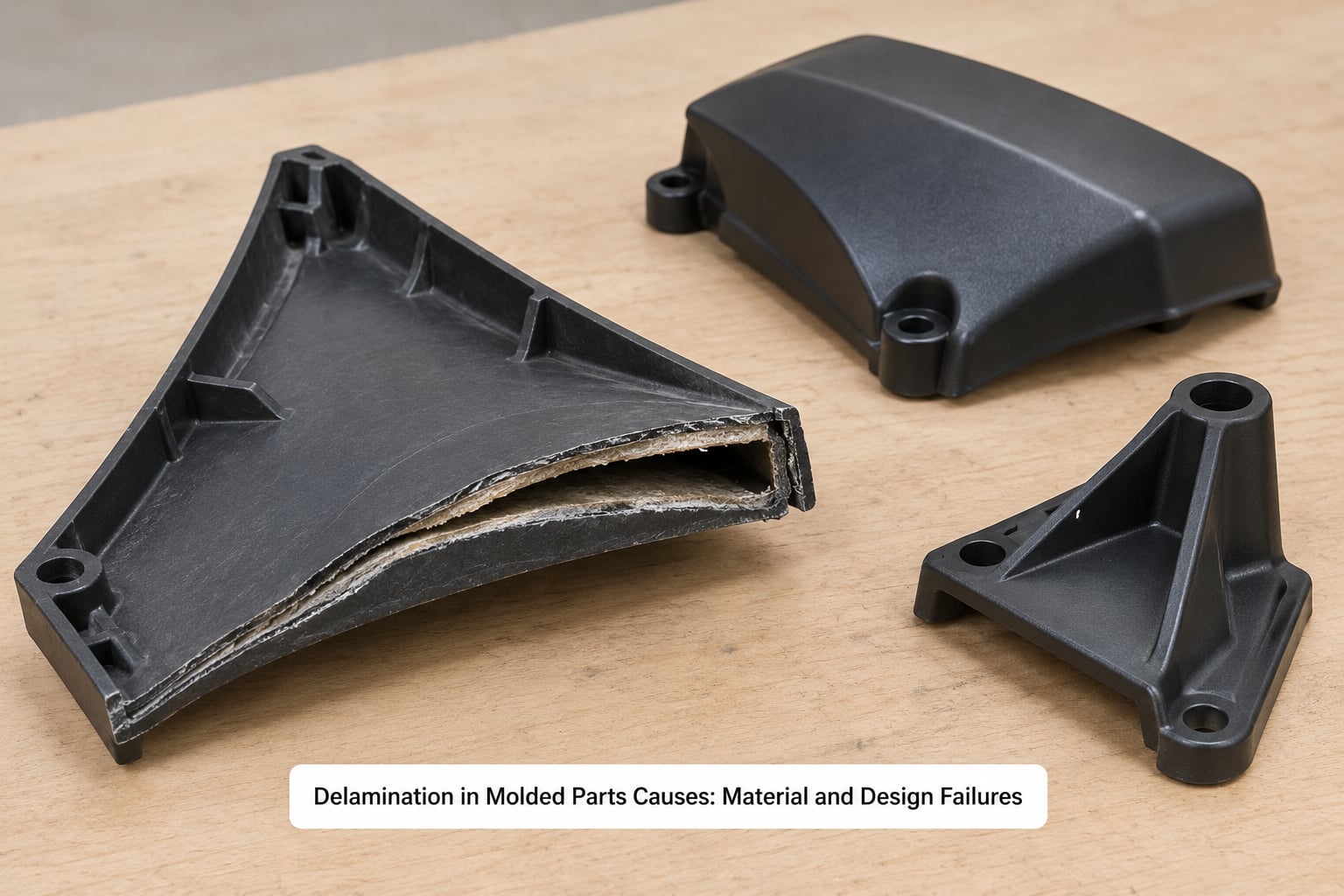
The fastest triage is to read the symptom, guess the cause family, then check the one thing that proves or kills that guess. Use the matrix below as a starting point, not as a verdict.
| Cause | Defect it tends to produce | First thing to check |
|---|---|---|
| Foreign material or cross-contaminated resin in the hopper | Localized peeling spots, sometimes only on some cycles | Purge sequence, hopper and dryer cleanout records, operator handling of regrind |
| Moisture in hygroscopic resin | Bubbles, splay, internal separation near the skin, reduced strength | Dew point of the dryer air, material moisture, dwell time inside the dryer |
| Incompatible regrind or wrong polymer in the blend | Weak, dull skin that peels in sheets; intermittent by batch | Regrind ratio and its polymer identity against the virgin grade |
| Mold release agent over-applied or the wrong chemistry | Every part affected, dull skin, poor adhesion of printing or plating | Release application rate and cycle interval, cavity wipe frequency |
| Poor pigment, filler or fiber dispersion | Mottled skin, chalky patches, weak zones with no clear pattern | Mixing time and temperature on the compounding line, screw wear |
| Excessive packing or holding pressure | Delamination at thick sections and near the gate, plus high stress | Pressure profile versus fill time, gate size versus part weight |
| Injection speed or velocity too high | Layered peeling parallel to the flow direction, splay streaks | Machine fill time versus part volume, shear rate at the gate |
| Mold temperature too low, or uneven across the cavity | A cold skin that never fuses to the core under it | Coolant channel balance, heater thermocouple check, mold surface temperature |
| Geometry: thick-to-thin steps, sharp corners, poor gate placement | Interruption of fusion lines and stress concentration in one repeatable spot | Wall transition radii, rib thickness ratios, gate location against the failure zone |
Two of those rows deserve a note. First, contamination and moisture account for most cases, because both leave a nearly identical signature: a defect that shows up on a percentage of cycles rather than every cycle. Second, release agent is the only cause here that is normally 100 percent reproducible, which is a useful way to split the suspect list in half.
What Causes Delamination in Molded Parts During Molding?
Moisture, gas and contamination all do the same thing at the microscopic level: they put something between two layers that were supposed to become one. The result is a weak plane you cannot see from outside.
Moisture in the resin
Hygroscopic polymers — polyamide, polycarbonate, PET, polycarbonate blends, and many ABS and acrylic grades — absorb water from the air. That water flashes to steam at melt temperature, and expanding vapor creates micro-gaps and pressure inside the melt. The symptom is usually splay or silver streaks near the gate, bubbles, and surface separation that appears in the first half millimeter of wall thickness.
Check the dryer itself, not just the setting. A hopper dryer running at a temperature that is too low for the resin, fed with ambient air through a leaky filter, or holding resin for hours beyond its recommended dwell time will produce wet material no matter what the setpoint says. Dew point is the number that matters.
Entrained gas and volatiles
Gas comes from several directions: moisture, degradation of the melt at too high a temperature or too long a residence time, and air trapped in the cavity by a poor vent or a back pressure set for foaming. Trapped gas gets compressed and then expands at a weak interface, and the layers around it never make contact.
If delamination appears only after a long idle period before start-up, suspect residence time and melt temperature. If it tracks with vent depth, it is a venting problem. Undersized vents also promote flash and short shots at the same time, so look for those companions.
Contamination and incompatible recycled material
A foreign polymer in the hopper behaves like a release film between layers: it does not fuse, and the skin lifts off it. Cross-contamination happens in shared grinders, shared dryers, shared drums, and anywhere regrind from one part number feeds another. Small amounts of a dissimilar polymer can do it at 2 percent in the blend.
Regrind of the same polymer is a different problem, and a common one. Regrind has already been through the process once, so its chains are shorter and its interfacial strength is lower. Above the supplier’s recommended ratio, a part can look perfect and still peel. Ultrahigh molecular weight polyethylene is a well-known case: it is famously difficult to mold without layered separation near the skin, because the very long chains orient along the flow direction and resist re-fusing. See our companion piece on what causes brittleness in plastic parts for the related chain-degradation mechanism.
Poor pigment, filler and fiber dispersion
Aggressive pigment or filler agglomerates act as stress concentrators and local barriers to bonding. With glass or carbon reinforcement, poor dispersion also means fiber breakage and a fiber-rich skin over a resin-poor core, and the boundary between them is a delamination site waiting to open.
Weak coupling between fiber and matrix is a formulation problem, not a machine setting. If the reinforced grade has a history of interface failures that follow the fiber orientation, review the grade’s coupling agent and consider a compatibilizer before touching the mold.
Molding Conditions That Trigger Layer Separation
Process settings rarely create delamination on their own. They create it when they freeze the melt before the layers have time to interdiffuse, or when they push a pressure differential into a weak interface. These are the settings to check first, after material.
Injection speed and velocity
Fast fill lays down a layered melt front that has less time to fuse. The layers stack, and the interfaces between them become the path of least resistance. Excess velocity at the gate also raises shear rate, which breaks glass fibers and can thin the reinforcing skin. Slower, staged fill is usually the first correction.
Melt temperature
Too low a melt temperature increases viscosity, so the front pushes harder and cools faster before it wets the layer ahead of it. Too high a melt temperature degrades the polymer and generates gas. The workable range is narrower than most people set, and it moves with the grade and the regrind ratio.
Mold temperature
This is the most common single trigger. A cold cavity wall freezes the first layer of polymer against the steel instantly. That frozen skin has no chance to bond to the material arriving behind it, so you get a peelable layer exactly at the wall, with sound material underneath. Raising mold temperature, slowing the fill, and bringing melt temperature down toward the middle of the grade’s range are the three adjustments that usually go together.
Packing and holding pressure
Excessive pack pressure squeezes material away from the core and generates residual stress, and that stress opens a marginal interface later. Conversely, insufficient hold leaves voids and voids invite delamination around them. Gate size relative to part weight sets the pressure you need; a very small gate into a heavy part asks for pressures that will stress the whole body.
Cooling time and cycle-to-cycle variation
Cooling that starts before the interface temperature is high enough keeps the skin frozen. And a mold that heats up over a shift changes the surface temperature cycle by cycle, which is why a defect can appear at hour three and vanish after lunch. Log cavity surface temperature, not just coolant temperature, if you can.
Cooling imbalance across the cavity
A mold with uneven channels has a warm half and a cold half, and delamination will show up only on one side of the part. Rotate the part in the fixture and check whether the failure follows the part or the position in the machine. It almost always follows position.
Part Geometry and Wall Structure Problems
Design does not create the bond, but it decides where the bond is asked to do the most work. Several geometry patterns reliably interrupt fusion.
Abrupt thickness changes
Where a 2.5 mm wall meets an 8 mm boss, the melt front cannot fuse across the step the way it does in a uniform wall. Flow lines diverge, orientation rises at the transition, and residual stress peaks there. A gradual transition or a generous corner radius gives the front room to reorient.
Thick sections and skin layers
Thick sections cool slowly in the core while the surface chills fast, so the outside shrinks at a different rate and time than the inside. That mismatch is exactly the residual stress that later peels the skin. Thin skins over a thick core are worse than uniformly thick or uniformly thin parts.
Sharp corners and zero radii
Sharp internal corners force the flow front to split and rejoin around them, producing a weld line with weak strength behind it. Add a radius consistent with the wall thickness. This is standard design practice for strength reasons; it is also a delamination fix.
Gate placement and flow direction
A gate that forces the front to wrap around the part puts orientation and a fusion boundary right where you do not want one. Place the gate where the flow is longest and straightest, and orient it so the last-arriving material lands on a non-critical wall rather than on a sealing surface or a boss root.
Ribs and boss roots
Industry guidance is to keep rib thickness near half the nominal wall and to round the rib root. Thicker ribs and square roots triple the local mass and create their own skin-to-core stress. If delamination clusters at every rib root on the part, stop adjusting the machine and redesign the ribs.
Incompatible flow directions between shots
In a multi-shot or overmolded part, the first-shot flow direction and the second-shot flow direction rarely match. Where the directions are perpendicular, the interface has a poor bonding geometry by design. That particular cause has to be solved in the tool, usually with mechanical interlocks or a texture in the substrate.
How to Confirm the Actual Failure Mechanism
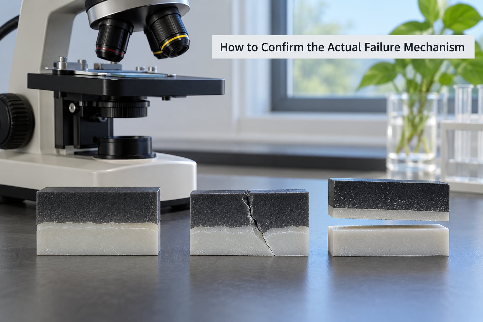
Most wasted troubleshooting time comes from working on the wrong cause. Confirm the defect and its location before you change anything.
- Document the part. Record part number, cavity, cycle count, machine, and every material lot, dryer setting and regrind ratio used in the run. Most process data dies within a month, so capture it now.
- Map the location. Mark where the peeling starts relative to the gate, the parting line, the vents, the ejector pins and the corners. Location is the fastest cause-family discriminator you have.
- Examine the surface. Look for a peelable skin you can lift with a fingernail, a lifting edge that follows a flow path, and a change in gloss or color underneath. A defect that peels in a sheet leaves a distinct boundary; a crack does not.
- Section the part. Cut through the suspect zone with a clean saw and examine the cross-section. Delamination shows a flat, shiny, clearly separated plane with a visible gap. A weld line shows a faint V at the surface with a thin seam behind it. A void shows a round or lens-shaped cavity.
- Magnify. Under a hand lens or cross-section microscope, look at the interface. A clean smooth plane means no bonding took place. A rough torn plane means the bond existed and later failed, which points to aging or overload rather than contamination.
- Test the material. Karl Fischer moisture on the pellets as molded, DSC or a simple melt-flow check for degradation, and a compatibility screen if regrind is in the blend.
- Test the part. Peel or tensile coupons on the suspect zone. ISO 294 covers tensile testing of plastics, and ASTM D522 covers the bend behavior relevant to cracking versus layer separation. These numbers give you a defensible acceptance limit instead of an opinion.
- Verify the fix. After one controlled change, section parts from the corrected run and compare the interface to the baseline.
Here is how the look-alikes separate at the bench. This distinction is where most misdiagnosis happens, because the parts all look vaguely flawed to an untrained eye:
| Defect | Appearance | What causes it |
|---|---|---|
| Delamination | Peelable skin or a flat internal plane with a visible gap | Failed interlayer bond from contamination, moisture, gas or a cold skin |
| Weld line | Faint V-shaped line on the surface, often with slight gloss change | Two flow fronts meeting around a hole or the far side of a boss |
| Silver streak or splay | Bright silvery streaks along the flow direction, near the gate | Moisture, gas, or degraded melt releasing volatiles |
| Void | Round, lens-shaped or irregular cavity inside the wall | Trapped gas, shrink void from insufficient hold, or thick-section cooling |
| Blister | Raised bubble that pops or dents under pressure | Gas behind a skin, often from a leak or a thick section |
| Sink mark | Shallow depression on a flat surface, no separation | Shrinkage in a thick section |
Is delamination a critical defect?
Treat it as one by default. A delaminated part has a locally weakened cross-section, and a defect that reduces structural continuity is damage unless you have evidence it cannot propagate. For cosmetic-grade parts with no sealing, structural or load-bearing function, a documented risk assessment may allow a limited area or count. For anything structural, sealing, medical or food contact, delamination is a reject, full stop.
| Factor | Cosmetic delamination | Structural delamination |
|---|---|---|
| Location | Hidden area, or a face with no function | Near a sealing surface, boss root, rib, hole or load path |
| Extent | Bounded area within a written limit | Any occurrence, or no stated limit |
| Effect on function | None identified in the risk assessment | Reduces stiffness, seal integrity, or fatigue life |
| Disposition | Accept per drawing note, rework only if approved | Reject and scrap; do not rework by hiding it |
Rework is usually a mistake. Heating and re-forming a delaminated part does not restore interfacial bond strength, and filling the gap with adhesive introduces a dissimilar material into a part whose failure mode you still do not understand. Where dimensional inspection is part of your quality plan, the CMM methods described in our CMM inspection basics guide will tell you whether the geometry held, but it will not find a buried weak plane.
How to Prevent and Correct Delamination in Molded Parts
Work in this order, and change one variable per trial. Changing three settings at once tells you nothing when the defect halves but does not disappear.
- Verify material condition first. Run moisture on the pellets, check the dryer dew point and dwell time, and audit the hopper, dryer and grinder for cross-contamination. This step catches the majority of cases and costs almost nothing.
- Control the regrind. Hold regrind to the same polymer, from a known source, at or below the supplier’s recommended ratio. If you see delamination on some cycles but not others, trace it to which drum was on the feeder.
- Rebalance the process window. Raise mold temperature, slow the fill in stages, and bring melt temperature to the middle of the grade’s range rather than the top of it. Then re-check holding pressure against gate size.
- Balance the mold temperatures. Verify coolant flow and heater output, and measure cavity surface temperature across the tool if you can. A defect that follows position in the machine is a mold balance problem until proven otherwise.
- Review release agent application. Cut the application rate and increase the wipe interval. If the tool has never run without release agent, build up polished steel surfaces on the cosmetic areas and let the tool run release-free. Mold polish is the real fix; release reduction is the compromise.
- Redesign where the geometry is the cause. Add radii at wall transitions, bring ribs down to roughly half wall thickness, move the gate away from the failure zone, and add interlocks or texture at an overmolding interface.
- Validate and document. Run a controlled trial, section parts, and record the change in the process sheet and the control plan. Add an attribute to incoming inspection if the defect is not fully eliminated.
- Plan for the aged failure. If the interface was marginal, it may open in the field. For parts that ship and sit, run an environmental stress check on the retained samples rather than shipping on a clean bench result alone.
If you cannot find a process or material cause after the above, the honest conclusion is that the interface strength is below what the design demands. That is a specification problem, and no parameter change fixes it.
Frequently Asked Questions
Can delamination appear immediately after injection molding?
Yes, though the visible peeling often appears later. Bond failure happens at ejection, but the skin often stays attached until it is flexed, cooled fully, or exposed to heat and humidity weeks afterward. Check parts at ejection and again after 24 to 72 hours of aging, and always section some parts rather than judging by hand.
Which plastic molding processes are most susceptible to delamination?
Injection molding of fiber-reinforced thermoplastics, multi-shot and overmolding, and UHMWPE are the usual trouble spots. Compression and transfer molding of rubber and thermosets show the same defect through rubber to metal or fabric interfaces, and CNC milling of laminated stock produces a similar-looking separation caused by cutting force rather than by molding at all.
Does delamination mean the plastic is contaminated?
Not always. Contamination is one of the most common causes, but a cold mold skin, moisture vapor, entrained gas, excessive pack pressure and a sharp thickness step can all produce the same symptom. The useful test is whether the defect affects every part or only some: contamination and moisture tend to appear intermittently, while mold temperature and release agent problems show up consistently.
How can a quality team distinguish delamination from cracking or voids?
Section through the suspect area. Delamination gives a flat, shiny, continuous plane with a visible gap and a surface skin that peels in a sheet. Cracks are narrow and irregular with sharp tips, and voids are round or lens-shaped cavities without a separating layer. Under magnification, delamination interfaces are either smooth with no bonding or torn where a bond existed and later failed.
Should a molded part with delamination be reworked or scrapped?
Scrap it if the part is structural, sealing, medical or food contact, because rework does not restore interfacial bond strength and hides an unresolved process cause. Cosmetic-grade parts with no functional surface may be accepted only against a written limit in the drawing or control plan. Regrinding affected parts without fixing the cause simply moves the defect into the next part.
Conclusion
Start with material condition and contamination, because those two account for most cases and cost the least to rule out. Then map where the delamination sits on the part against your gate, vents, corners and mold-temperature zones, and let that location pick the cause family. Make one controlled correction, section parts from the corrected run to confirm the interface, and only then release the job. If nothing in the process window fixes it, the bond strength the design is asking for was never there.