
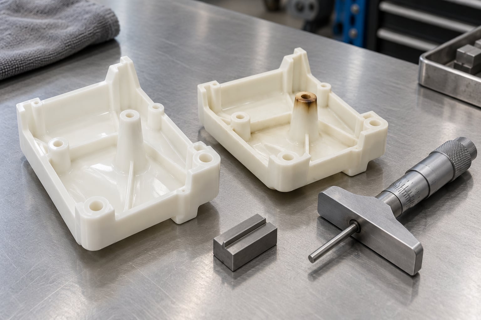
Burn marks in injection molding happen when air trapped inside the cavity is compressed by the advancing melt front, heats up through adiabatic compression, and chars the plastic surface. The mark itself is a symptom, not a disease: the trapped gas, a degraded melt, a hot mold spot or contaminated resin can each produce the same brown streak. In most shops the fix is ventilation work on the tool, not a change to the recipe.
This guide walks through what a burn mark actually looks like, where on the part it appears, and the twelve corrective actions that reliably clear it. The order matters. Most teams who chase barrel temperature first waste a shift before anyone opens the tool and looks at the vents.
Table of Contents
- What Burn Marks in Injection Molded Parts Look Like
- Burn Marks in Injection Molding Causes: A Quick Diagnostic Guide
- Burn Marks in Injection Molding Causes by Location
- 12 Proven Fixes for Burn Marks in Injection Molded Parts
- 1. Open up the vents at the last-fill zone
- 2. Widen the vent land, not just the depth
- 3. Re-balance flow between cavities
- 4. Move or add a gate to change the fill pattern
- 5. Profile the injection speed through the last fill
- 6. Trim packing pressure and hold time
- 7. Bring melt and mold temperature down into the process window
- 8. Dry hygroscopic resin to the documented specification
- 9. Eliminate contaminated and degraded material
- 10. Clean and repair cavity surfaces
- 11. Fix hot spots in the cooling circuit
- 12. Set residence time and startup limits as a standard
- How to Prevent Burn Marks from Returning
- When to Change the Mold, Material, or Process Window
- Frequently Asked Questions
- Conclusion: What to Check First
What Burn Marks in Injection Molded Parts Look Like
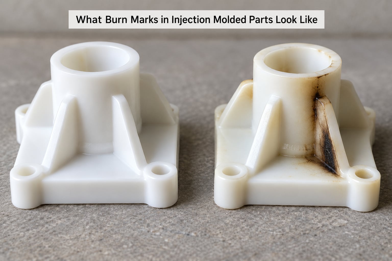
A burn mark is a brown, tan or black discoloration with a soft, smoky edge. On a black part you see it as a dull, mottled patch that reflects light differently than the surrounding gloss. On a white or clear part it looks like a tea stain or scorch halo.
Five other defects get called a burn mark by mistake, and telling them apart saves the diagnosis:
- Silver streaks are thin, bright metallic lines running in the flow direction, caused by a tiny amount of moisture at the melt surface. They are light-catching, not discolored.
- Weld lines show as faint lines or notches where two flow fronts meet. They are structural and visible by touch, not just by colour.
- Gloss differences come from inconsistent packing or melt temperature and shift with process settings rather than staying pinned to one spot. What causes sink marks in injection molded parts covers the opposite failure mode and is worth reading alongside this one, since a thin wall behind a burn mark usually means shrinkage had nowhere to go.
- Flash is extra material squeezed past the parting line, thicker than the wall, and always along an edge rather than scattered across a face.
- Contamination marks appear as discrete dark specks or streaks with hard boundaries, sometimes visible as black flecks embedded in the wall.
Two observations narrow things fast. Note where the mark sits relative to the gate, and note whether it appears on every part or only some. A mark on every cycle points to a fixed feature in the tool. A mark that wanders or shows up on one cavity out of four points to flow balance or material condition.
Burn Marks in Injection Molding Causes: A Quick Diagnostic Guide
The table below maps the common causes to what you see, where you see it, and the first thing to change. Burn marks in injection molding causes are easiest to separate by location, because the mold tells you where the gas went.
| Cause | Typical appearance | Where it shows | Cycle behavior | First corrective action | Verify by |
|---|---|---|---|---|---|
| Trapped air, inadequate venting | Sooty brown patch, sharp scorch line | End of fill, deep boss tips, blind rib pockets | Every part, same spot | Open or add vent land depth at the last-fill zone | Depth micrometer reading on the land, patina on the land after a run |
| Flow imbalance between cavities | Mark on one cavity only | Last-fill zone of the slow cavity | Every part, one cavity | Rebalance runner or gate size; verify fill simulation | Short shot series showing different fill per cavity |
| High injection speed | Mark that moves when speed changes | Weld line intersection, end of fill | Worsens above a speed threshold | Add a slower profile through the last 15 percent of fill | Two parts, one setting changed, same cycle time |
| Excess packing pressure or time | Dark streak along weld line | Weld line, thin sections | Scales with hold pressure | Trim hold pressure or hold time in small steps | Part weight and dimension response over three hold settings |
| Excessive melt temperature | Even, dull discolouration, odour | Wide area, worst at end of flow | Consistent, worse in long cycles | Drop barrel or nozzle temperature by small steps | Smell and colour over three temperature settings |
| Moisture or volatiles | Silver streaks plus occasional brown fizz | Roughly the whole part | Worse after material sits open, better after drying | Verify and record the drying step, then dry to the resin spec | Moisture reading and a repeat run on dried pellets |
| Contaminated or degraded regrind | Hard black flecks, burnt smell at the barrel | Scattered, random | Random part to part | Purge and run virgin resin to isolate the material | Clear pellets and colour-free barrel for a full run |
| Hot spot, friction, or rough cavity surface | Localized black char, sometimes with a scrape line | Fixed steel area, ejector interference | Every part, grows as mold warms | Check cooling and mold temperature, inspect cavity surface | Surface inspection, mold temperature reading, parting-line check |
| Long residence time in the barrel | Dull colour, black specks after long idle | Whole part, worst on the first shots after a stop | Worst after downtime | Reduce barrel capacity used, set a shutdown purge schedule | First shots after a soak compared with steady-state shots |
A mark that hugs the end of fill almost always means gas. A mark that sits a short distance from the gate, right where the resin took the worst shear, means the melt is degrading before it ever reaches the last-fill zone. Both are called burns on the shop floor, and they need opposite corrections.
Burn Marks in Injection Molding Causes by Location
Trapped Air and Incomplete Venting
As molten resin fills a cavity, it displaces the air that was there. Air that cannot escape ahead of the melt front is squeezed into a shrinking volume, and by Boyle’s Law the temperature of that trapped gas climbs sharply in a fraction of a second. The plastic next to it is held at melt temperature while being cooked by compression alone. That is the diesel effect, and the brown streak it leaves is the single most common burn mark in molding.
Gas traps form wherever flow splits around a boss, meets itself after circling a deep core, or arrives last at a pocket corner. Thin ribs leading off a thick boss are the classic offender, as is any blind hole that has no parting line running past it. If the last-fill contour ends inside one of those features, that is where the mark goes. Venting problems in injection molds explained goes deeper on why trapped gas shows up where it does and how vent geometry interacts with the fill pattern.
Check the tool before you touch the machine. Vent land depth is measured from the parting surface, and typical starting ranges run roughly 0.001 inch for easy-flowing materials up to 0.002 inch for glass-filled nylon and similar filled grades, with a land width of about 0.060 to 0.125 inch behind the depth and a relief cut beyond it. Confirm those numbers against your resin supplier’s data rather than treating them as universal. Forums are full of tools delivered with a correct depth but a land width so narrow that flow resistance through the vent is worse than the pressure the vent was supposed to relieve.
Ejector pins are often doing all the venting at a boss tip, and only by accident. The annular clearance around the pin is the vent, which is why reducing pin diameter by 0.0005 to 0.001 inch sometimes opens the flow that the land never did. If you find yourself widening a vent to fix it, check the land width first. Vent land width is what sets the flow capacity, not the depth alone.
A depth micrometer, a short-shot series, and a hand lens tell you most of what you need before anyone opens a laptop. Fill simulation in Moldflow or Moldex3D is worth running when the imbalance is not obvious, but it is a supporting tool here, not the first step.
Overheating From Speed, Pressure, or Cycle Time
The second burn mechanism is the melt itself getting too hot. Injection speed generates shear heating across the gate and through thin sections, packing pressure adds compression at the weld line, and long residence time in the barrel degrades the resin until it can no longer take the heat of the process. Any of the three will brown the plastic, and the pattern tells you which one is active.
Speed-driven burns move when you move the setting. Cut the fill rate by a third and the seam-line discoloration usually shrinks or disappears on the same shot, which is the cleanest evidence you can get without a trial. If nothing changes, speed is not your problem.
Packing-driven burns scale with pressure and hold time in a fairly predictable way. Watch part weight and the critical dimensions as you trim hold pressure in small steps. Where the mark fades while the weight stays on target, hold pressure was doing damage the part did not need.
Residence-time burns show up after a stop. After a lunch break or a nozzle change, the first shots off the machine are dull and sometimes speckled, then the colour recovers. That pattern is a barrel-capacity problem, not a settings problem, and it is solved by using a smaller screw for the job or by scheduling a purge.
Moisture, Volatiles, and Contamination
Hygroscopic resins — nylon, PET, polycarbonate, ABS in many grades — pull moisture out of the air while the pellets sit in the hopper. The water becomes steam in the melt, and you get silver streaks first and, with enough moisture, fizz and brown discolouration on top. Drying is the fix, and a written record of it is the proof: date, material lot, dryer temperature, dwell time, taken from the resin supplier’s specification rather than from a habit that happened to work on one part number.
Contamination looks different. Black flecks with hard edges, burnt smell near the nozzle, or a dark streak that appears on a random part every so often point at something that broke off in the machine, dirty feed system material, or burned material sitting in the manifold. A Reddit thread on unexpected black spots on molded parts drew exactly that list from experienced users: contamination breaking off the screw or barrel, a contaminated feed system, and burned material in the manifold. The way to settle it is to purge and run a full shot of virgin resin. If the marks vanish, the resin lot is your suspect; if they persist, the machine is.
Oil from a compressor leak, dust from the molding room, release-agent residue, or a mix of two grades in the same regrind stream all produce gas or colour at the surface. Clean the feed path and the hopper, verify your regrind ratio against what the resin allows, and keep regrind bins labeled and covered. This is not glamorous, and it fixes more intermittent burns than any setting change.
Mold Temperature and Surface-Related Causes
A cavity that is too hot lowers the freezing point enough that the skin on the part is still soft when the tool closes. Friction against a tight clearance, a rough or damaged cavity surface, and an ejector that has been adjusted slightly out of alignment all generate heat at one fixed spot. The plastic in contact with that steel browns and chars from the outside in.
The distinguishing feature is that these marks do not care about your settings. Change the recipe and the mark stays exactly where it was, because the cause is metal meeting plastic at a point of contact. Look for polish, drag marks, or a witness line on the cavity surface where the char appears, and check the ejector-plate alignment and the clearance around every pin. Then check the mold temperature controller on the zone nearest the mark. A blocked or fouled cooling passage will put a hot spot exactly where the discoloration is, and it will get worse as the shift continues and the tool heats up.
Roughness is worth treating on its own. A cavity polished to a consistent finish across all faces gives you one place to look when a mark shows up later. A patch of tool marks in an otherwise smooth face is an invitation for the next cosmetic defect.
If the marks appear on a surface that has to be seen and the tool is the cause, stop trimming settings. It will not improve.
How to Diagnose the Root Cause Step by Step
Engineers across molding forums consistently rank short shot progression as the most valuable diagnostic step, and it works because it shows you where the melt front actually stopped. Here is the sequence I would follow on a shop floor.
- Document the defect. Photograph the mark with the part in the same orientation each time. Mark its position relative to the gate, the parting line, and any ejector pin. Record cycle number, cavity number, and machine settings at the moment of the shot.
- Decide random or consistent. Count marked parts over 50 cycles per cavity. Every part at the same spot means a tool feature. Random or cavity-specific means flow balance, material condition, or machine wear.
- Run a short shot series. Shorten the hold or the injection time in steps so you get a part that fills 30, 60, and 90 percent. Mark where the melt front stopped each time. If the burn sits inside the last 10 to 15 percent of the fill, you have a gas trap at that feature.
- Inspect the tool. With the mold open and clean, check every vent land for patina, polymer residue packed into the depth, and for damage. Confirm depth and land width with a depth micrometer at several points. Look at ejector clearance and parting-line contact around the marked area.
- Verify material. Check the drying record, then check reality: weigh a sample of dried pellets against the target on your moisture analyzer before they enter the hopper. Pull a sample from the hopper and inspect it for contamination and for black specks.
- Make one change. Change a single variable and leave the rest alone. Two changes at once and you will not know which one moved the mark.
- Confirm against clean parts. Run a batch large enough to see the difference and compare marked against unmarked parts on the same setup.
Acceptance is simple enough to write on the setup sheet: 500 consecutive cycles with zero marks on the critical face, and the vent depth reading recorded in the log. A fix you cannot measure is a fix you have not proven.
12 Proven Fixes for Burn Marks in Injection Molded Parts
These are corrective actions, not causes. Each one is distinct, and each one needs its own verification step.
1. Open up the vents at the last-fill zone
Measure the existing land, clear packed resin out of the depth with a vent-cleaning tool, and restore it to the depth and width your resin calls for. Verify with a depth micrometer and then with a short shot series showing the fill now completing past that feature.
2. Widen the vent land, not just the depth
A tool delivered with a correct depth and a narrow land will not flow. Widening the land to the range your resin supplier recommends is often the whole fix when depth was already right. Verify by measuring width and confirming the land shows even patina across its full length after a run.
3. Re-balance flow between cavities
Where one cavity fills last, correct the imbalance at the runner or gate rather than slowing the whole tool. Sizing up the gate on the slow cavity, or correcting a runner that feeds it poorly, evens the last-fill contour. Verify with a short shot series across all cavities and a fill simulation if you have one.
4. Move or add a gate to change the fill pattern
Moving the gate away from the feature that traps gas, or splitting the flow so no single pocket arrives last, removes the trap instead of fighting it. Verify by confirming the burn location shifts to a new, non-critical area or disappears entirely.
5. Profile the injection speed through the last fill
Fill fast, then slow the profile over roughly the last 15 percent of stroke so the melt front advances gently while gases escape. Verify by comparing the seam-line mark at the same speed change with and without the profile.
6. Trim packing pressure and hold time
Reduce hold pressure or hold time in small increments and watch both the mark and the part dimensions. Keep the highest setting that still holds weight and dimension. Verify with a short shot series and a dimensional check on the critical features.
7. Bring melt and mold temperature down into the process window
Lower barrel and nozzle temperature by small steps within your resin’s specified range rather than dropping everything at once, and correct a mold temperature controller that is running warm. Verify by colour and odour across three consecutive settings.
8. Dry hygroscopic resin to the documented specification
Use the resin supplier’s temperature and dwell time, size the dryer to the hourly throughput so pellets are not sitting damp after the first hour, and keep the dryer and hopper closed. Verify with a moisture reading taken before the pellets reach the hopper and a repeat run on properly dried material.
9. Eliminate contaminated and degraded material
Purge the barrel, clean the feed path and hopper, remove material that has been reheated past its limit, and set a ceiling on regrind ratio. Verify by running a full batch of clean, color-sorted resin and confirming the flecks disappear.
10. Clean and repair cavity surfaces
Polish rough faces, remove drag marks, and correct any ejector interference or alignment that is rubbing the part. Verify by inspecting the surface under raking light and by confirming the witness mark no longer transfers to the part.
11. Fix hot spots in the cooling circuit
Where the mark grows as the tool warms, trace the cooling line nearest it and clear the blockage or correct the controller. Verify by logging mold temperature over a run and confirming the differential across the two mold halves narrows.
12. Set residence time and startup limits as a standard
Match barrel capacity to the shot volume, define a purge schedule for shutdowns, and set a maximum idle time before the first shots are quarantined. Verify by comparing first shots after a planned soak with steady-state parts.
How to Prevent Burn Marks from Returning
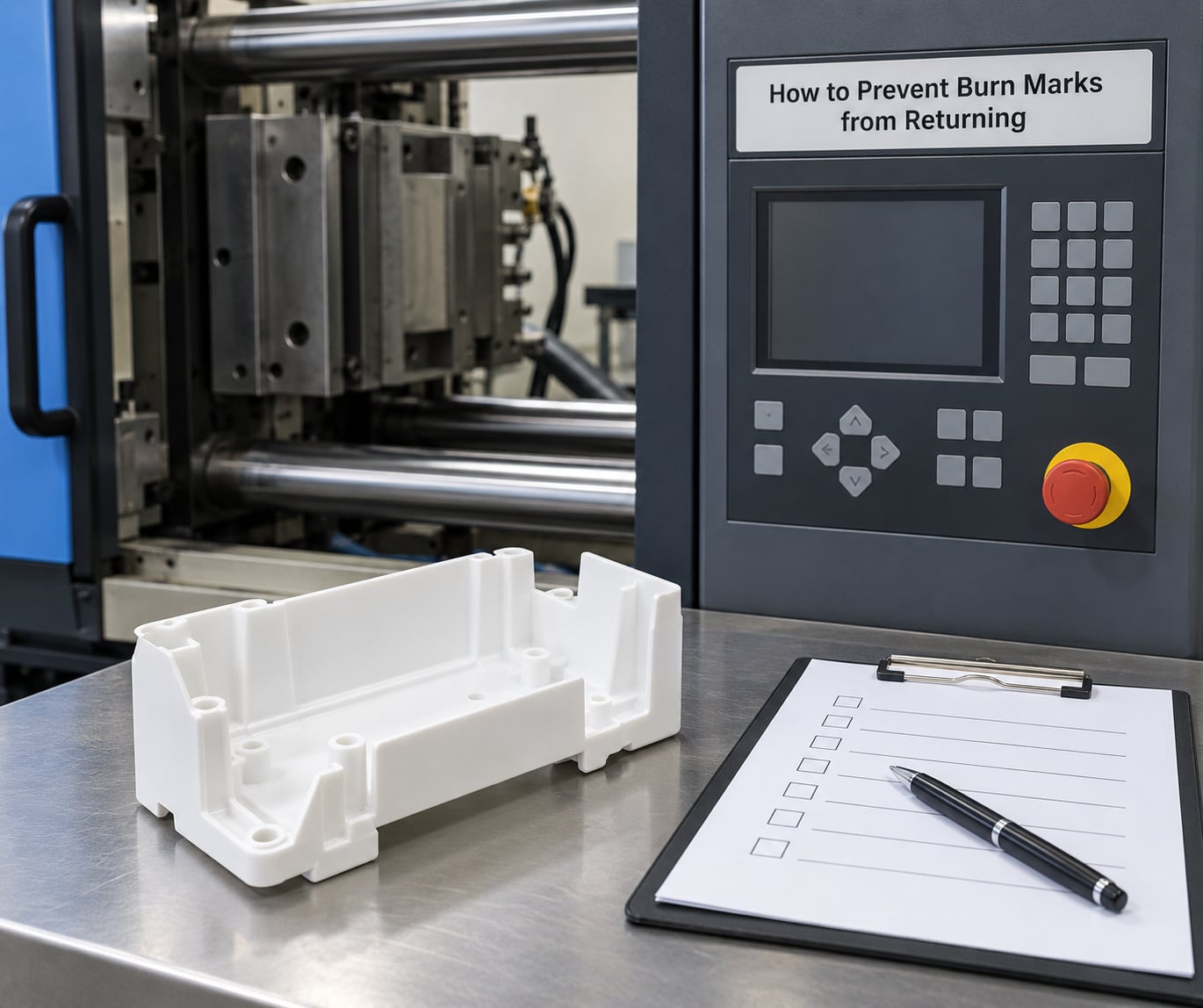
A burn mark that was fixed by venting but never documented will come back with the next mold change, the next material lot, or the next operator. Turning the fix into a habit is the difference between a good week and a good year.
- Incoming material checks. Sample each lot, screen for contamination, and verify moisture before release to production.
- Drying records. Log lot number, dryer temperature, dwell time, and moisture reading against the supplier specification.
- Vent inspection on a schedule. Put vent lands on the mold maintenance list with the depth micrometer, not a visual once-over. That routine is covered in more depth in a mold maintenance schedule for injection molding.
- Process-window limits. Put acceptable ranges on the setup sheet so speed, hold pressure, and temperature have defined boundaries rather than individual preferences.
- Startup and shutdown procedures. Write down what happens in the first ten shots and after a long idle, including whether first shots are quarantined.
- Operator training. Teach the crew to read a burn mark by location before anyone changes a setting. Most misdiagnosis on this defect comes from a barrel temperature change made before anyone looked at the tool.
- Monitoring for intermittent defects. Track defect rate by cavity and cycle count so a fault that appears once in 400 shots is still caught.
Where marks land on cosmetic surfaces, note the risk in your control plan. Burn marks that are invisible on a hidden face and unacceptable on a visible face deserve different acceptance criteria, and writing them down prevents the argument later.
When to Change the Mold, Material, or Process Window
Some problems cannot be solved from the machine. Escalate when you hit any of these conditions.
The geometry traps gas by design. A blind boss 1.5 inches deep or a core that flow cannot reach from the parting line needs real venting hardware, such as a sintered vent insert sized to the feature, or a vacuum venting system. No setting change reaches inside a pocket that has no exit path.
Venting was never designed in. This is common on tools built offshore where the specification was never checked against the feature. The work needed is vent land rework, ejector clearance changes, or insert installation. Judge it on payback: steel work against the annual cost of rejected parts. If the tool has been running years with a small scrap rate, a slow tooling fix may not pay for itself.
The gate is the problem. A gate that puts high shear on a thin wall, or that forces fill into a corner, will burn regardless of venting. Gate relocation or resin change at the gate becomes the fix. Compute shear rate at the gate against the resin’s guidance before committing.
The material is the limit. Some filled or high-temperature grades tolerate very little shear before they degrade. Moving to a higher-flow grade or a glass-filled version with better dimensional stability often solves a burn that no setting can touch.
The process window needs revision. If the defect only appears at a speed or temperature you need for cycle time, the window itself has to change, and that means a documented requalification rather than an informal override on the machine.
Escalate when trial changes have failed twice with evidence recorded, when the defect touches a cosmetic face, or when parts in the field are functionally affected. Charred material is brittle, and a burnt gate region can be a stress concentration. Cosmetic only is one thing; strength loss is another.
Frequently Asked Questions
Are burn marks in injection molded parts caused by moisture?
Sometimes, but rarely on its own. Moisture produces silver streaks and bubble marks first, because water vapor forms at the melt surface. It causes brown discoloration only when enough steam is generated to char the resin, which usually happens alongside trapped air. Check the dryer record and take a moisture reading before blaming moisture for a mark that sits at the end of fill every single cycle. That pattern is a vent problem.
Can burn marks be removed from an injection molded plastic part?
Not reliably. The discoloration is charring of the polymer itself, not a surface coating, so solvents barely touch it and abrasion only removes material. Light cosmetic marks can sometimes be masked on painted parts, but a burn on a visible face is normally scrap, and polishing a textured surface leaves a visible flat spot. Fix the cause in the tool or the process rather than trying to repair the part.
Does reducing injection speed always fix burn marks?
No. Speed changes help when the burn is driven by shear heating or by air that cannot escape a rapidly advancing melt front. They do nothing for a vent that is blocked, a cavity that has damage, contaminated material, or a mold temperature hot spot. Test it properly: change only the speed, hold the cycle time steady, and see whether the mark moves. If it stays exactly where it was, the cause is elsewhere.
Are burn marks a sign that the plastic is defective or unsafe?
A burn mark means the resin was overheated or burned at that location, so the affected area can be brittle and weaker than the rest of the part. On a cosmetic face with no structural load, that is usually a quality rejection rather than a safety concern. Anywhere the mark sits near a gate, a weld line, or a load-bearing section, treat the part as suspect and confirm the loss of strength with your material supplier before it ships.
When should a mold be inspected or repaired for burn marks?
Inspect as soon as a mark shows up at the same location on consecutive parts, because that pattern means a fixed tool feature. Repair when measurement shows the vent land is shallower than specification or packed with resin, when an ejector is rubbing, or when the cavity surface is rough at the mark. Also inspect after any mold change, crash, or maintenance period before the tool returns to production, and record the depth reading in the log.
Conclusion: What to Check First
Start with location. Compare marks across several parts and ask whether the mark lands at the end of fill, near the gate, at a boss tip, or on one cavity only. Then open the tool and measure the vents with a depth micrometer, checking land width and ejector clearance at the same time. Confirm the material is dry and clean by measurement, not by assumption. Make one controlled process change and compare marked against unmarked parts.
Burn marks in injection molding causes come down to evidence, not to lowering every setting at once. The mark is telling you where the problem is. Read it before you touch the machine, and write down what you find.