
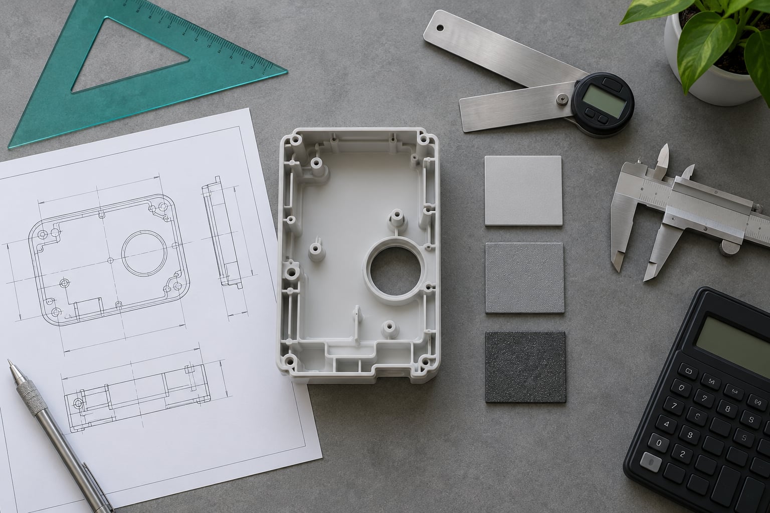
Draft angle is the slight taper you put on a wall so the part releases from the mold instead of hanging up in it. Most injection molded features run between 1 and 3 degrees, and draft angle guidelines for injection molding ask for more as depth, texture, and material stiffness increase. The six steps below show how to assign, calculate, and verify draft on your own part.
A part that sticks does not just get scraped and retried. It stops the line, marks the cavity, and can break ejector pins. Getting draft right in CAD costs minutes. Getting it wrong in the tool costs a week.
Table of Contents
- What You Need Before You Assign Draft
- Step-by-Step: Developing Compliant Draft Angles
- Common Draft Mistakes and How to Correct Them
- Frequently Asked Questions
- What is the difference between draft angle and taper in injection molding?
- Can an injection molded part have a zero-draft face?
- How do you calculate draft for a deep pocket or tall boss?
- What draft angle should be used for a molded-in texture?
- Should draft be shown on a part drawing for manufacturing?
- When does a moldmaker need to approve a low-draft design?
- Conclusion
What You Need Before You Assign Draft
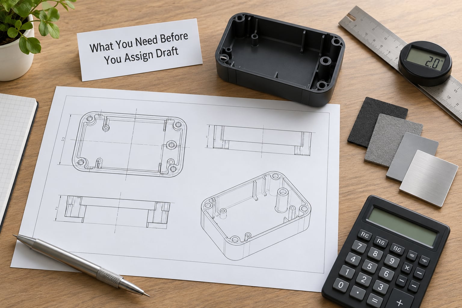
You cannot pick a draft angle in isolation. It is a function of the pull direction, the depth of the feature, the resin, and the surface finish, so gather these inputs first.
- Finished CAD geometry with feature depths measured, not eyeballed. Depth is the number the whole calculation hangs on.
- Material data: resin family, unfilled or glass filled, and the nominal shrinkage rate. Filled grades change both draft need and surface behaviour.
- Surface finish specification, including any molded-in texture and its depth in microns.
- Intended parting line and pull direction, either decided or at least sketched in two or three options.
- The cosmetic faces that a customer or end user will see, so draft transitions land somewhere acceptable.
- Supplier or in-house DFM feedback, ideally from the same mold builder who will quote the tool.
- A calculator and an angle protractor, for the arithmetic in step 4 and for checking the print later.
One caution up front. Complex textures, high shrink variation between grades, and any feature that needs a side action rather than a straight pull deserve a mold-specific review. The numbers below are starting points for straight-pull geometry, not universal constants.
Step-by-Step: Developing Compliant Draft Angles
The workflow runs in a fixed order on purpose. Parting line first, because it decides the pull direction, which decides which walls need draft at all. Angle second, feature by feature, and verification last. Skip ahead and you end up with a correct angle on a wall that never releases.
1. Identify Surfaces That Need Draft
Start by separating surfaces that must release during mold opening from faces you deliberately hold parallel to the pull. Not every face takes draft, and the ones that do not are usually the ones that cause trouble.
Outer sidewalls on a cavity half release outward as the mold opens, so they need positive draft on every face. Cores that form inner features need draft that opens toward the core, so material releases as the core draws. Ribs, bosses, pockets, and drafted undercuts each behave the same way, just along a different axis.
Two categories are different. Faces held by a side action, such as a slider or lifter, must also let the moving steel clear, so they carry their own draft in the direction that action travels. Faces you want flat, such as a sealing gasket land or a label face, are often held parallel on purpose and marked as exceptions.
How do you tell which is which? Trace the mold opening direction first. Any surface whose normal is parallel to the pull needs draft. Any surface perpendicular to the pull sits on a parting plane and does not.
2. Establish the Parting Line and Pull Direction
Set the parting line before you set a single angle, because the parting line fixes the pull direction and the pull direction fixes every draft value in the model. A split placed one millimetre differently can force draft onto a face you wanted flat, or remove draft from the wall that binds hardest.
Placing a split on a visible face means the flash line and the draft transition both land in view. Where you can, put the parting line on a flat, non-functional surface that the parting tool can reach. Uniform wall flow around the cavity also suffers when the split is put somewhere awkward, since material has to bend around the parting geometry.
Draft normally runs from the parting line outward, so the largest cross-section sits at the split and the section narrows toward the deepest point. This is the opposite of the additive approach used in die casting, and it is a common source of confusion. Gate position travels with all of this, so review our guide to gate placement mistakes to avoid in injection molding in the same pass.
3. Select the Starting Draft by Material and Surface
There is no universal draft angle. The 1 to 3 degree range quoted everywhere is a starting point for unfilled, semi-gloss thermoplastics, and it moves with the resin and the finish.
High-flow polyolefins such as PP and PE release easily and tolerate roughly 0.5 to 1.5 degrees. Polycarbonates and ABS sit in the middle, commonly 1 to 2 degrees. Polyamides behave differently, since low shrinkage combined with higher surface friction pushes recommendations toward 2 to 4 degrees. Glass-filled grades add stiffness and surface drag, so treat them at the upper end of the resin’s range and confirm with the supplier.
Finish matters as much as resin. Polished and high-gloss surfaces hide draft transitions well, which is an advantage, but they show witness marks and drag streaks that a low-draft textured surface would hide. Molded-in texture is the opposite case. A widely used rule from the Boulderes resource is 1.5 degrees of draft for every 0.001 inch, or 0.025 mm, of texture depth, applied per side. Deep cavities get their own allowance too, with one guideline adding 0.5 degrees for every 10 mm of depth.
Say plainly on the drawing that these are starting points. The resin grade and the texture family both change the answer, and the mold builder’s number should win when the two disagree.
4. Calculate Draft Over the Full Feature Depth
The taper calculation is simple. The angle is the arctangent of the width change divided by the depth: theta equals the arctangent of X over H, where X is the total width change across the feature and H is its depth.
Here is a worked example. Take a pocket 40 mm deep with a 25 mm dimension at the mouth. You want 2 degrees of draft on each side. X per side equals 40 mm multiplied by the tangent of 2 degrees, which is about 1.4 mm. Two sides give 2.8 mm, so the bottom of that pocket is 22.2 mm across, not 25 mm.
Watch the distinction between one-sided draft and total taper. A cross-section drawing labelled with the full included angle shows 4 degrees on that pocket, because two 2 degree walls add up. If the mould maker reads 4 degrees as the per-side value, the feature comes out 5.6 mm undersized. State clearly which you mean on the drawing.
Deep features, long cores, and shrink all push the real release angle above the nominal one. Add extra where the feature is deeper than about 30 mm, and add more again when the part cools unevenly and pulls toward the core, since that deflection fights the draft you paid for.
5. Apply Draft Angle Guidelines to Each Feature
Now apply the selected values consistently, feature by feature, and resist the temptation to type one global angle into the CAD draft command. A single global value is fine for simple prismatic parts and wrong for almost everything else.
- Outer walls: the baseline angle from step 3, referenced to the parting line, added from the split outward.
- Inner cores: the same or a slightly larger angle, referenced to the core parting line, so release improves as the core draws.
- Ribs: draft on the rib flanks referenced to the wall base, not the top, otherwise the rib becomes knife-edged at the parting plane.
- Bosses: draft on both outside and bore, with the inner draft typically one degree more than the outer to protect the core pin.
- Pockets: use the full pocket depth in the calculation, not the depth to the first obstruction.
- Transitions: never step from one angle to another in a single edge. Blend over a short length, usually 1 to 2 mm, so the toolmaker cuts one smooth radius instead of a fragile notch.
Some features need local relief rather than more angle. A hole that breaks into a pocket, a rib that meets a boss, or a wall interrupted by a snap-fit hook each want a small added taper at the interruption. Preserve critical dimensions by controlling one reference dimension, usually the largest one at the parting line, and letting the taper carry the rest of the variation.
6. Document and Validate the Design
A drawing that says “draft 2 degrees” with nothing else is not a specification. Mark the base dimension and the end dimension for each drafted feature, the feature depth, the parting line, the pull direction arrow, the texture family and direction, and every permitted exception such as a zero-draft sealing face.
Run a CAD interference or draft analysis next. The analysis highlights faces with less than the specified angle and surfaces that would move sideways during opening, which is exactly the list you want to review by hand. Each flagged face is either a mistake or a documented exception.
Send the annotated model to the mold builder before the tool is cut, not after. Ask them to confirm pull direction, draft on cores and lifters, and the parting line in writing, and get a DFM report back that you keep with the model. Where the geometry is unusual, ask for a simulation or a short trial before committing to production volumes.
Common Draft Mistakes and How to Correct Them
Draft problems cluster into a handful of repeatable patterns. Each one shows up in the same place on the sample part, which means you can diagnose it on the shop floor without a microscope.
Missing or inconsistent draft
Symptom: the part hangs up on one wall and releases cleanly from the rest. Correction: find the face flagged by the CAD draft analysis and correct it to the base angle. Verify: section the model at the parting plane and confirm every outer wall is within half a degree of the others.
Excessive draft on a controlled surface
Symptom: assembly gaps appear at a mating interface even though the part looks clean. Correction: reduce draft only on the controlled face, hold the mating dimension, and move the compensation to a non-functional surface. Verify: stack the part with its mate and check the fit at three positions.
Draft referenced to the wrong depth
Symptom: a shallow feature releases fine while a neighbouring deep one drags. Correction: recalculate using the full depth of the deep feature and re-cut the transition blend. Verify: re-run the draft analysis and compare the reported angle against the calculated one.
Abrupt angle transitions
Symptom: a witness line or drag mark at a shoulder, or a nick in the tool steel. Correction: extend the blend to 1 to 2 mm so the toolmaker cuts one continuous surface. Verify: look for a smooth line in the finish rather than a hard step under raking light.
Draft assumed from the nominal angle alone
Symptom: first shots eject fine, then failures appear as the tool wears. Correction: review shrink, ejection area, and whether the feature is holding a vacuum, which is the same physics behind preventing flash in injection molding and the related tooling fits.
Zero-draft faces with no release path
Symptom: a face drafted to zero because a drawing said the mating surface must be flat, and trapped air on that face. Correction: give the face a vent at the last point to fill, and decide whether it can take 0.5 degrees. Verify: walk through our explanation of venting problems in injection molds and check the face is vented before it fills last.
Quick Checks Before Tooling Release
Run this list in order before the tool is released for machining.
- Pull direction is marked on the drawing and agrees with how the part will be removed or picked up.
- Parting line sits on a non-critical surface and is achievable with a standard parting tool.
- Every zero-draft face is listed as an exception, with a reason and a vent location.
- Minimum release area and ejection surface are sufficient for the part mass and the automation.
- Texture family, depth, and direction are specified where texture meets a drafted surface.
- Base and end dimensions are both given for every feature whose size matters.
- Draft on lifters and sliders clears in the direction the action travels.
- Cavity balance and cooling considerations are reviewed, since differential cooling changes effective draft.
- The mold builder has returned written DFM feedback and the model is frozen against edits.
The first action is smaller than that. Open your CAD model, set the pull direction, and section the part at the parting plane. That single view shows you which walls have draft and which do not, and everything after it depends on it.
Frequently Asked Questions
What is the difference between draft angle and taper in injection molding?
Taper is the physical widening or narrowing of a feature, usually expressed in millimetres. Draft angle is that same feature expressed as an angle between the wall and a line parallel to the pull direction. They describe identical geometry from two directions, so 1 mm of taper over a 40 mm depth and about 1.4 degrees of draft are the same design choice. Drawings tend to mix them, which is a common source of confusion.
Can an injection molded part have a zero-draft face?
Yes, but it should be deliberate. Sealing faces, gasket lands, and some label areas are often specified at zero draft and listed as exceptions on the drawing. The cost is ejection and appearance: a parallel wall relies on mold release agent, can drag and scuff, and traps air at the end of fill. If the face can take 0.5 to 1 degree, the part will eject more reliably and still seal.
How do you calculate draft for a deep pocket or tall boss?
Use theta equals the arctangent of X over H, where H is the full depth of the pocket or boss and X is the width change across it. For a 40 mm deep pocket at 2 degrees, X is about 1.4 mm per side, so a 25 mm mouth becomes roughly 22.2 mm at the bottom. Add extra angle as depth grows, since shrinkage and core deflection both fight the release you designed.
What draft angle should be used for a molded-in texture?
Base the angle on the texture depth, not on the finish alone. A common rule is 1.5 degrees of draft for every 0.001 inch, or 0.025 mm, of texture depth, applied per side. A fine texture may leave you near 2 to 3 degrees, while a coarse one pushes well past that. Specify the texture family on the drawing, because the same nominal pattern number can cover a range of actual depths.
Should draft be shown on a part drawing for manufacturing?
Yes, and show the dimension, not just the angle. Give the base dimension at the parting line and the end dimension at the deepest point, plus the feature depth, the parting line, and the pull direction. If a face is held at zero draft, mark it as an exception with a reason. Angles alone leave the toolmaker guessing which dimension is controlled and how much tolerance to hold.
When does a moldmaker need to approve a low-draft design?
Any time a face sits at or below about 0.5 degrees, sits parallel to the pull, or relies on a side action to release. Deep cores, large textured areas, and heavy parts picked by automation deserve the same review. Send the model with the exceptions marked and ask for written confirmation of pull direction and core draft. Mold makers see the ejection and gating consequences that a drawing alone does not show.
Conclusion
Reliable draft starts with the parting line and the pull direction, then adds material-specific release allowances, then gets checked feature by feature. Begin with the visible and mating surfaces, since those are the ones that will fail loudly. Send the annotated model to the mold builder and resolve anything uncertain before the tool is cut.