
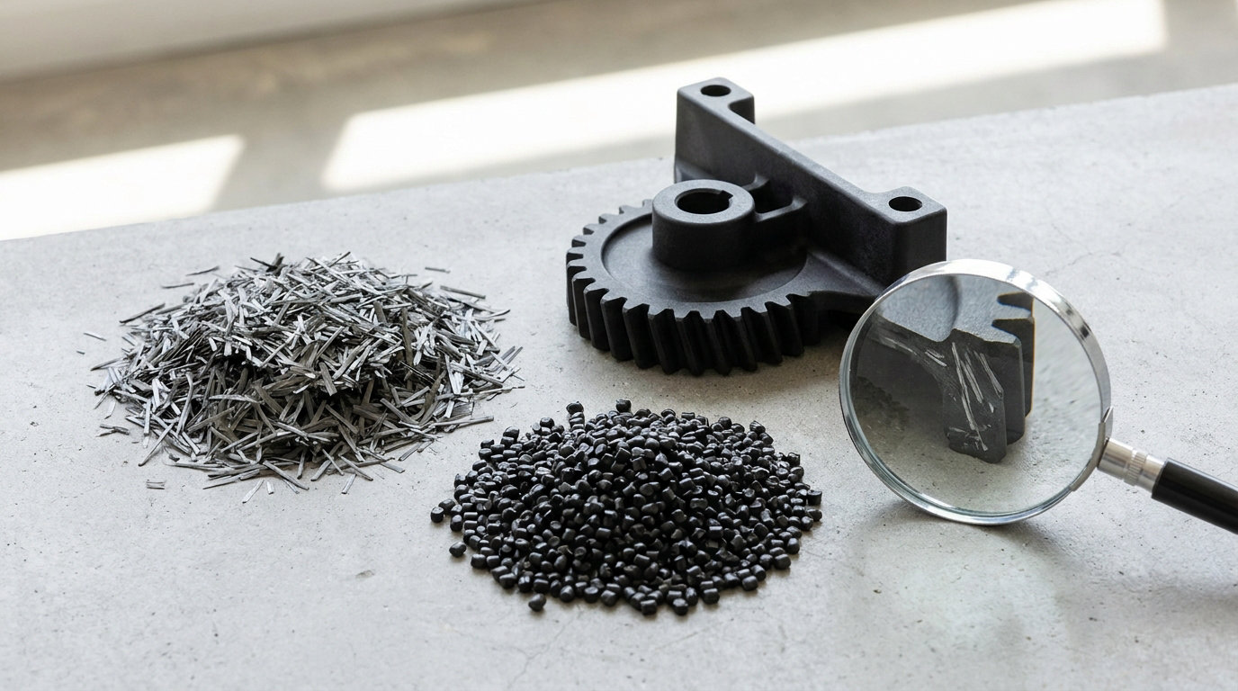
Carbon fiber filled plastic is a molded thermoplastic resin that has been compounded with chopped or continuous carbon fiber, usually 10 to 30 percent by weight, so the fiber carries load and stiffens the part while the resin binds it together and holds its shape. The important detail is that this is not carbon fabric in epoxy. It is a pellet you feed into a normal plastic molding machine, and that difference drives most of its properties, its cost and its limits.
I get asked about this material in two very different ways. A buyer wants to know whether it can replace a die-cast aluminum bracket and what it will do to the unit cost. A maker wants to know why a carbon fiber nylon print feels tough while a carbon fiber PLA print snaps. Same filler, opposite behaviour, and the answer sits in the resin and the fiber length rather than in the carbon itself.
This guide covers what carbon fiber filled plastic actually is, how the fiber changes performance, which resins and processes pair well, where the material earns its place, and where it will disappoint you. Updated for 2026.
Table of Contents
- What Are Carbon Fiber Filled Plastics?
- Carbon Fiber Filled Plastic Properties at a Glance
- How Do Carbon Fibers Change Plastic Performance?
- Which Processing Methods Work Best?
- Where Are Carbon Fiber Filled Plastics Used?
- What Are the Main Disadvantages?
- How Do Cost and Fiber Content Affect Material Selection?
- How Do You Choose the Right Grade?
- Frequently Asked Questions
- Are carbon fiber filled plastics stronger than unfilled plastics?
- What difference does carbon fiber content make?
- Can carbon fiber filled plastics be injection molded?
- Are carbon fiber filled plastics electrically conductive?
- Can carbon fiber filled plastics be recycled?
- Is carbon fiber filled plastic suitable for outdoor use?
- Conclusion
What Are Carbon Fiber Filled Plastics?
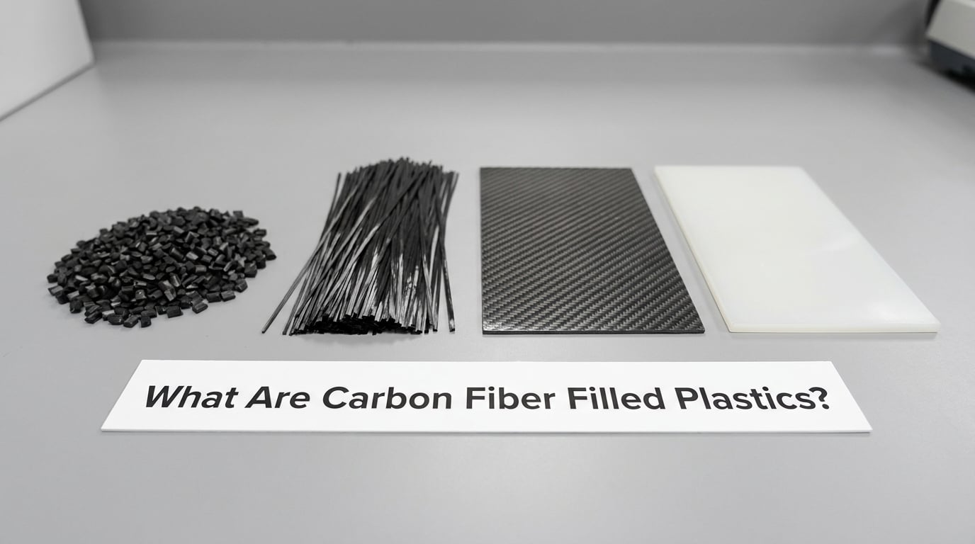
Carbon fiber filled plastic is a polymer matrix reinforced with short or continuous carbon fibers, compounded so the fiber disperses through the melt and survives the molding process. The resin gives shape, impact toughness and processing ease. The fiber gives stiffness, dimensional stability, wear resistance and electrical conductivity. Neither one does the job alone.
The terminology trip people fall into most often is the words filled versus reinforced. Industry data sheets use them interchangeably, which is why a supplier page rarely settles the question for you. In practice, filled means the fiber is compounded into the bulk of the melt and is present throughout the part, while reinforced describes a structure where fiber is deliberately placed where load runs. Injection molded housings are filled. A prepreg layup schedule is reinforced.
That gives three working categories, and mixing them up is the single most common source of bad material choices:
- Short or chopped fiber reinforced thermoplastic (SFRT) — fiber typically under one millimeter in the finished part, compounded at 10 to 30 percent, injection molded on standard tooling.
- Long fiber reinforced thermoplastic (LFT) — pellets carrying 10 to 12 millimeter fibers, which retain one millimeter or more in the molded article and deliver a large jump in stiffness.
- Continuous fiber composite — unidirectional, woven or braided fabric or tows held in epoxy or thermoplastic, cured in an autoclave or press, used for primary aerospace and motorsport structures.
Carbon fiber itself starts as a polyacrylonitrile precursor, gets stretched and carbonized above 1000 degrees Celsius, and ends up as a filament roughly 5 to 10 micrometers across. A tow is the bundle of those filaments, and the common tow designations you will meet, 3K, 6K and 12K, simply count thousands of filaments per tow. Everything downstream depends on what happens to that tow after it meets the resin.
Carbon Fiber Filled Plastic Properties at a Glance
No single table covers this material properly, because chopped, long and continuous fiber grades behave differently in nearly every column. Here is one that does.
| Property | Chopped fiber (SFRT) | Long fiber (LFT) | Continuous fiber composite |
|---|---|---|---|
| Matrix | Thermoplastic, PP through PEEK | Thermoplastic, mostly PA6, PA66, PP, PPS | Epoxy, vinyl ester or thermoplastic sheet |
| Reinforcement form | Chopped fiber dispersed in melt | 10 to 12 mm fibers in pellet form | Continuous tow, unidirectional or woven |
| Typical loading | 10 to 30 percent by weight | 20 to 40 percent by weight | 50 to 60 percent by volume in laminate |
| Stiffness in the fiber direction | Moderate gain over unfilled resin | Large gain, close to continuous fiber approaches | Highest available |
| Impact and toughness | Best of the filled grades | Moderate, sensitive to notch and weld lines | Lowest, brittle with hidden damage risk |
| Electrical behavior | Conductive, useful for static dissipation | Conductive | Conductive along fiber paths, variable across the laminate |
| Density | Lower than unfilled resin, carbon is lighter than most polymers | Lower still at high loading | Lowest of the three |
| Surface finish | Smooth mold surface, visible fiber at edges and cut faces | Smooth with fiber swirl pattern | Needs finishing to hide weave |
| Processing method | Injection molding, extrusion, 3D printing | Compression molding, injection molding, extrusion | Autoclave, press, vacuum bag, filament winding, pultrusion |
| Shrinkage | Low but anisotropic, warpage is the main risk | Low, warpage controlled by fiber cross-section and flow | Near zero along fibers, negative coefficient in some directions |
| Main limitation | Cost premium over glass fiber and unfilled resin | Narrow processing window, higher fiber breakage risk | Not moldable on normal plastic tooling, poor recyclability in thermosets |
How Do Carbon Fibers Change Plastic Performance?
Carbon fibers are extremely stiff along their length and remarkably weak on their own, since a single filament crushes under a fingertip. Dispersing them through molten resin transfers load into thousands of fibers at once and stops them buckling, and that buckling failure is where nearly all of the stiffness gain comes from. The engineering trade is that you buy stiffness, dimensional stability and conductivity, and you pay for it in ductility, toughness and surface quality.
Five variables decide how much you gain and how much you lose.
Fiber content. Going from 10 to 20 percent by weight is the single biggest lever, because stiffness scales roughly with volume fraction. It is not linear, and it stops being useful past the point where the melt can wet out every fiber. Suppliers cap most grades at 20 to 30 percent for exactly that reason.
Fiber length. Longer fibers transfer load across more of the part, which is why LFT grades exist at all. If your process shears a 10 millimeter pellet fiber down to 200 micrometers in the barrel, you paid a long fiber premium and received a short fiber part.
Fiber orientation. Molding flow aligns fibers along the flow direction and leaves them nearly random across it. A part is therefore stiffer along its flow path and more compliant across it, which is the source of nearly every warpage complaint in filled molded parts. Fibre orientation is the variable a mold flow simulation exists to predict.
Sizing. The thin chemical coating on each filament decides whether the fiber bonds to the melt or slides inside it. Poor sizing gives you a part that looks fine and fails at the interface.
Distribution. Clumped fiber, dry spots and weld lines all appear as local weakness rather than as a uniform property change, so they are invisible in a datasheet and obvious on a part.
Two results are counter-intuitive enough to be worth stating plainly. Adding carbon fiber commonly raises stiffness while lowering tensile strength, ductility and toughness in the unfilled comparison, which is exactly what makers report when a carbon filled print snaps instead of bending. And because the fibers bridge the matrix, filled thermoplastics creep far less under sustained load than the parent resin, which is often the more valuable gain in a structural bracket than raw modulus.
How Carbon Fiber Filled Plastics Are Made
The fiber is produced from a polyacrylonitrile precursor that is stretched, stabilized in air and carbonized in an inert atmosphere, then oxidized, stretched again to full modulus and surface treated. Most molded compound is then made in a compounding line: the resin is dried, the fiber is cut to length, and both are metered into a twin screw extruder that melts, disperses and pelletsizes the blend.
At the molding shop the sequence is stricter than most people expect. Pellets are dried to the resin’s moisture limit, since wet nylon and polycarbonate make brittle parts and splay marks. The screw is sized generously, 35 mm or larger for serious production, with low back pressure and a modest compression ratio so the fiber is not cut to pieces in the barrel. Gates are placed so flow matches the part’s stiffness pattern, and multiple gates get balanced or the weld lines between them become the weak point.
Incoming and outgoing quality checks are unglamorous and worth doing: fiber length distribution on the pellets, moisture content before molding, melt flow rate, and a short flow or gate marking check on the first shots off a new tool. A fill pattern that has been blended flat is a good sign. Fiber breakage does not show up in a tensile coupon from a well-molded gate.
What Resins Are Commonly Used?
The resin sets the temperature ceiling, the chemical exposure, the toughness and most of the price. Fiber content changes the stiffness, but it never rescues a resin that softens where the part operates.
| Resin | Processing temperature | Heat resistance | Chemical resistance | Cost level | Typical use |
|---|---|---|---|---|---|
| Polypropylene (PP) | Lowest, easy to mold | Low to moderate | Good against oils, weak to solvents | Low | Interior automotive clips, housings, large structural parts |
| ABS | Low, wide processing window | Moderate | Moderate | Low | Electronics housings, static dissipative trays |
| Polycarbonate (PC) | High, needs drying | Moderate to high | Weak to strong solvents and alkaline cleaners | Medium | Structural frames, lighting, high load thin walls |
| Nylon PA6 and PA66 | Medium, moisture sensitive | Moderate | Good, but absorbs water and loses stiffness wet | Medium | Gears, brackets, robotics links, functional prints |
| PET and PBT | Medium | Moderate | Good | Low to medium | Electrical components, connectors, dishwasher-safe parts |
| PPS | High, demanding equipment | High | Excellent, solvent resistant | High | Automotive underhood and electrical components |
| PEEK | Very high, needs special tooling and control | Very high | Excellent across solvents, acids and fuels | Very high | Aerospace, medical, semiconductor handling |
Thermosets such as epoxy and vinyl ester sit outside this family. They give higher stiffness and lower void content, but they do not melt, they are not injection moldable, and they are far harder to recycle. The performance gap between an epoxy laminate and a well-compounded thermoplastic is much smaller than the processing and end-of-life gap, which is why filled thermoplastics keep taking share.
Which Processing Methods Work Best?
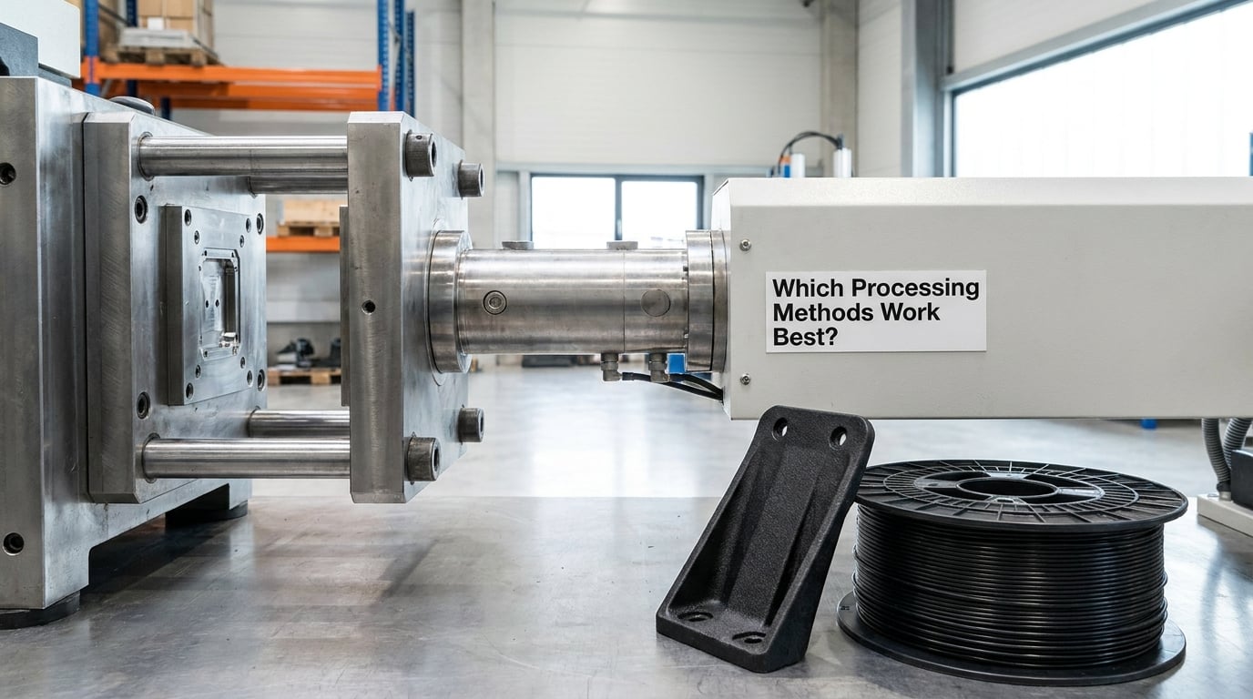
Injection molding is the default, because short fiber grades flow like the parent resin and drop into existing steel tooling. The constraint is screw design and shear: an aggressive screw, high back pressure or a high compression ratio shortens fiber in the barrel, and the datasheet stiffness never arrives in the part. Long fiber grades can be injection molded but are more often compression molded, where the charge is placed in the tool and only lightly fused.
Compression molding suits long fiber pellets and large panels because the fiber is not forced through a long narrow flow path. Extrusion suits profiles, rods and sheet that will be vacuum formed or thermoformed, and it also produces the 3D printing filament that carries the same chopped fiber.
Sheet forming and thermoforming work well with continuous fiber laminate sheet, which is how drone frames and computer cases get their stiffness. Additive manufacturing is the odd one out: filament printers melt a chopped fiber compound layer by layer, so each layer sees less effective reinforcement than an injection molded equivalent, and the nozzle must be hardened because the fiber is abrasive as sandpaper. That last point is the one most buyers learn the hard way.
Where Are Carbon Fiber Filled Plastics Used?
Electronics and static dissipative handling come first, and the reason is free electrical behavior. Once fibers touch each other the material conducts, so a carbon filled housing dissipates electrostatic discharge without a separate conductive coating or conductive paint step. Wafer handling fixtures, test sockets, carrier trays and server or drive housings use exactly this, and buying the conductivity as a property of the compound is far more reliable than a coating that wears off.
Automotive uses it for light brackets, instrument panel supports, underhood sensor mounts and any part that has to stay dimensionally stable near a hot engine. Nylon grades dominate here because they combine stiffness with moisture and chemical tolerance.
Robotics and industrial automation favor long fiber nylon for robot link housings, gripper bodies and fixtures, where creep under a static load decides whether the part is still accurate after a shift.
Aerospace and motorsport sit mostly in continuous fiber laminate: airframe panels, spars, propeller parts, control surfaces and racing bodywork. Where a molded part is acceptable, PEEK composites appear in hinges, brackets and semiconductor wafer handling where temperature and chemical exposure are extreme.
Consumer and recreational products are the least demanding and most visible category. Sports equipment, luggage, drone arms, camera gear and functional 3D printed parts all use carbon filled filament, usually at 10 to 20 percent loading. The rule of thumb from the printing community is simple and generally right: carbon fiber in nylon adds real strength, carbon fiber in PLA mostly adds stiffness.
What Are the Main Disadvantages?
It gets less tough, not more. The fibers bridge the matrix and stop it deforming, so a filled part is stiffer and often more notch sensitive. In practice, filled parts can fail suddenly instead of stretching first, and a low velocity impact can leave internal damage that is invisible until a tension test.
Cost. Carbon fiber costs multiples of glass fiber per kilogram, and you pay again in slower cycle times, more aggressive drying and higher scrap rates from short shots and brittle sprues.
Surface quality and exposed fiber. Cut faces, gate vestiges and any machined surface show fiber ends, and glass fiber equivalents do not. Molding surface finish is usually excellent, which is why cosmetic and structural parts look inconsistent side by side.
Anisotropic shrinkage and warpage. Shrinkage follows fiber alignment, so flow direction and cross flow shrink differently, and flat parts bow. This is a mold design and gating problem more than a material problem, but it is the issue that most often kills a project’s first production attempt.
Machining wear. Carbon fiber is abrasive and will destroy an uncoated carbide or HSS tool in minutes. Use diamond coated or PCD tooling, support the part well, and use a coolant path rather than a flood.
Electrical consequences. Conductive dust can form from cut fiber and needs extraction, and a design that required isolation can no longer rely on a plastic being an insulator. Check your insulation and grounding design again rather than assuming polymer behavior.
Recycling. Filled thermoplastics are recyclable in principle because the matrix melts, but fiber shortened by the recycling process gives a lower grade each cycle, and in practice most scrap goes to incineration or landfill. Continuous fiber thermosets are much harder. Request recycled content grades for molded parts and expect to pay a premium.
Moisture. Nylon grades absorb water and lose stiffness as they do, and the effect is permanent for the life of the part. Polycarbonate and PEEK are far less sensitive.
How Do Cost and Fiber Content Affect Material Selection?
The cost of a filled compound is driven by seven things, and they pull in different directions. Resin choice sets the baseline: PP and ABS at the bottom, PEEK at the top. Fiber grade and fiber length both add, and long fiber pellets cost more per kilogram than short fiber compounds. Loading level is close to linear in the material, and it is the lever buyers most often over-pull. Processing method, annual volume and secondary operations then decide the piece price: high volume amortizes setup, and welding, painting or plating a filled part can erase a resin saving.
Specification discipline matters more than any of them. Specify the minimum loading that meets the load case, not the highest that is available. Over-specifying costs money and takes away surface finish and impact resistance you did not need.
| Fiber loading | Material cost | Stiffness change | Toughness | Surface and flow | Typical fit |
|---|---|---|---|---|---|
| 10 percent | Low premium | Modest improvement | Best retained | Flows easily, smooth finish | Appearance parts, ESD housings, prototype volumes |
| 15 to 20 percent | Medium | Large improvement | Noticeable loss | Good flow, fiber visible at cut faces | The default engineering choice for most molded brackets |
| 25 to 30 percent | High | Large further gain | Noticeable loss | Shorter flow length, more warpage | Metal replacement where stiffness beats impact |
| Long fiber, 20 to 40 percent | Highest | Biggest gain, near continuous fiber | Reduced, notch sensitive | Compression molding, limited flow paths | Structural and automotive platforms, large panels |
Per kilogram, the same material can cost a small pilot order several times what a mature production program pays for the identical compound. Buyers comparing two quotes without checking the volume assumptions behind them are usually comparing two different products.
How Do You Choose the Right Grade?
Start with the load case, not the datasheet. Write down the peak load, the direction it comes from, the service temperature, whether the part is dropped or struck, and whether it must dissipate static or stay electrically isolated. Those five answers eliminate most of the catalog.
Then work through the remaining constraints:
- Operating temperature. Above the resin heat deflection temperature you are designing a cold part. Choose a higher grade family rather than hoping the fiber carries it.
- Load direction. Stiffness along flow is much higher than across it, so orient flow with the primary load or move to LFT.
- Impact demand. High drops and shock favor short fiber, a higher loading percentage, or a tougher matrix such as ABS or PC over PEEK.
- Electrical requirements. Want static dissipation? Carbon filled does it by default. Need isolation? Use glass fiber or a different reinforcement.
- Chemical exposure. Solvents, fuels and hot alkaline cleaners rule out PC and often PP, and push toward PEEK or PPS.
- Shrinkage and warpage tolerance. Tight flat parts mean slow uniform cooling, symmetric gate layout, fiber cross-section selection and mold flow simulation before the tool is cut.
- Surface finish and marking. Hidden structural parts tolerate exposed fiber. Cosmetic parts do not.
- Production volume. Below a few thousand parts a year, filament printing and machining can be cheaper than a steel tool.
- Recyclability requirements. A molded thermoplastic fits circular programs; a thermoset laminate does not.
Three worked cases. A semiconductor wafer handling arm that lives in a clean hot environment with solvent cleaning wants PEEK with carbon fiber, short fiber, and a design that treats the fiber as stiffness rather than as a conductor. An instrument panel bracket in a car, mounted near a hot vent and loaded in one direction, wants long fiber PA66 compression molded with flow aligned to the load. A drone arm prototype on a small budget wants a carbon filled nylon filament print first, because it validates the geometry before anyone cuts a tool for it.
Frequently Asked Questions
Are carbon fiber filled plastics stronger than unfilled plastics?
Usually stiffer, and often not stronger in tensile terms. Carbon fiber raises modulus, creep resistance and dimensional stability dramatically, but it can reduce tensile strength, elongation and impact toughness against the unfilled resin. Think of it as trading ductility for rigidity. If your part survives being dropped or struck, short fiber grades in ABS or PC are the safer pick than a high loading in a stiff resin.
What difference does carbon fiber content make?
Fiber content is the biggest single lever on stiffness, and the effect is roughly proportional to volume fraction, not weight percentage. Ten percent gives a modest improvement, 15 to 20 percent is the usual engineering sweet spot, and 25 to 30 percent pushes toward metal replacement at the cost of flow, surface quality and toughness. Above 30 percent most compounders cap the grade because the melt can no longer wet out every fiber.
Can carbon fiber filled plastics be injection molded?
Yes, and it is the main reason to use them. Short fiber grades flow on standard steel tooling with modest cycle time. The hardware matters: a generous screw, 35 mm or larger, low back pressure and a modest compression ratio keep fiber length intact, and gates should be balanced to avoid weak weld lines. Drying the pellets properly, especially for nylon and polycarbonate, decides whether the part is tough or brittle.
Are carbon fiber filled plastics electrically conductive?
Carbon fiber filled plastics conduct electricity once the fibers touch each other, which is why they are specified for electrostatic discharge protection in electronics housings, wafer carriers and test fixtures. The conductivity is a bonus rather than a controlled specification, so treat it as a dissipation path, not as a ground. The same property rules the material out of any design that needs electrical isolation.
Can carbon fiber filled plastics be recycled?
In principle, yes, because a filled thermoplastic still melts. In practice each recycling cycle shortens the fibers through shear, so the recycled grade is stiffer and less tough than the original, and most scrap ends up incinerated or landfilled. Continuous fiber thermoset laminates are much harder to recycle because the matrix does not melt. Ask suppliers for recycled content grades, and expect a premium over virgin compound.
Is carbon fiber filled plastic suitable for outdoor use?
Yes for structural outdoor parts, with checks in the right places. The resin governs UV, weather and hydrolysis resistance, so choose a stabilized grade or a UV stable matrix such as ABS or PC rather than assuming the fiber protects it. Carbon fiber itself does not degrade in sunlight, but exposed fiber at cut surfaces collects water, and the anisotropy that makes the part stiff also makes it prone to stress splitting in freezing conditions.
Conclusion
Carbon fiber filled plastics sit in a useful middle: stiffer, more dimensionally stable and often lighter than the resin they are based on, cheaper and far easier to process than continuous fiber composites, and tougher than a laminate. The trade is always the same, though. You gain rigidity, creep resistance and conductivity, and you give up ductility, surface quality and some of the money you saved.
So start at the beginning, with the load, the temperature, the electrical behavior, the geometry and the target piece price. Define those five, and the resin and fiber grade become a short list rather than a catalog. Pick the minimum loading that meets the requirement, prototype before committing to a tool, and run mold flow simulation on anything flat enough to warp.