
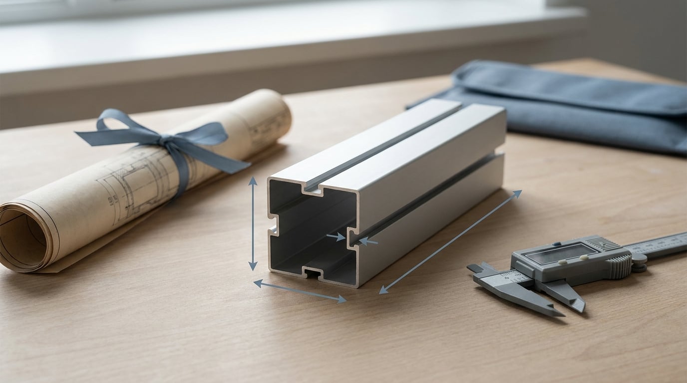
Profile extrusion tolerances explained starts with a number: standard aluminum extrusion tolerances run roughly ±0.1 to ±0.3 mm on most profile dimensions, and tighter bands are possible on the features that actually matter. Those values come from standards such as EN 755-9, EN 12020-2 and ASTM B221 with ANSI H35.2. Here is what the numbers mean, how they get set, and how to write them on a drawing so acceptance is not arguable.
The trap most buyers fall into is applying one tolerance value across an entire drawing. A curtain wall mullion, a heat sink base and a 2020 T-slot rail can all be bought to the same published standard and still behave very differently in your assembly, because the tolerance on a dimension depends on the dimension itself.
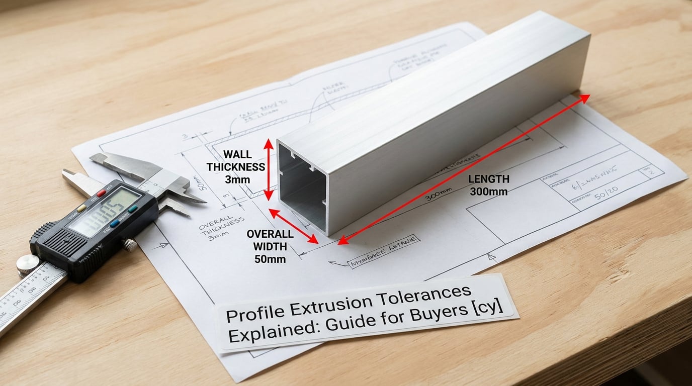
Table of Contents
- Profile Extrusion Tolerances at a Glance
- What Are Profile Extrusion Tolerances?
- Which Profile Dimensions Commonly Need Tolerances?
- Why Do Extruded Profiles Bow and Twist After Extrusion?
- How Profile Extrusion Tolerances Are Established
- How to Read Profile Drawings and Inspection Reports
- What Is the Right Tolerance for a Critical Feature?
- How Do Material and Process Changes Affect Tolerances?
- What Causes Common Profile Tolerance Failures?
- Frequently Asked Questions
- What are the standard tolerances for aluminum extrusion?
- What are the ASTM standards for aluminum?
- What is an open dimension in extrusion tolerances?
- What are the most common defects found in aluminum extrusion?
- What are the key differences between the 2020 and 4040 aluminum extrusion profiles?
- Does anodizing change extrusion tolerances?
- Conclusion: Start With the Critical Dimensions
Profile Extrusion Tolerances at a Glance
A tolerance is a permitted band around a nominal dimension, and the table below separates the terms that get used interchangeably on shop floors and in purchase orders.
| Term | What it means | Example | Why it matters |
|---|---|---|---|
| Nominal dimension | The size the drawing calls for | 50.00 mm | The starting point only; it is never an acceptance rule |
| Tolerance | The total width of the permitted band | ±0.50 mm | Determines whether a part passes or is rejected |
| Acceptance limits | The lowest and highest values allowed | 49.50 to 50.50 mm | What the inspector actually checks against |
| As-measured value | The reading taken on one part at one location | 49.62 mm | Only meaningful with a stated method and measurement point |
| Process capability | How tightly the extrusion line can actually repeat | ±0.20 mm repeatable | A tighter tolerance than capability means constant rejection, not tighter parts |
| Form deviation | Departure from true shape, not size | Bow of 1.2 mm per metre | Causes assembly stress and poor sealing even when sizes pass |
Everything below in this guide sits on the right-hand column of that table: knowing where a measurement comes from and what it controls.
What Are Profile Extrusion Tolerances?
A profile extrusion tolerance is the permitted variation in an extruded profile’s dimensions and shape. It exists because an extrusion is a continuous process, so no two meters of a 6 m length come out of the die identical.
Tolerances are usually bilateral, written as ±0.30 mm, which allows equal deviation either side of nominal. Unilateral limits such as 0 / −0.50 mm or 50.00 +0.30 / −0.10 mm push the whole band to one side, and they are used where a part can never be undersized for function but can be slightly oversized, such as a shaft or spigot feature on a sliding track.
Three things get confused with tolerance constantly, so keep them apart:
- Specification tolerance is what the purchase order permits.
- Process capability is what the extruder can repeat lot after lot.
- Defects are things a tolerance never permits, such as a die line, bubbles, a weld seam in a hollow, or a crack.
A part can be dead centre of its tolerance and still be defective, and it can sit at the edge of a generous tolerance and be perfectly usable. Compliance and function are separate questions.
Which Profile Dimensions Commonly Need Tolerances?
Not every dimension on an extrusion needs a callout, because the standard already covers most of them. These are the characteristics most buyers end up adding, either because the standard value is not enough or because a supplier needs clarity.
| Characteristic | How it is normally controlled | Typical buyer concern |
|---|---|---|
| Overall size (width, height, across flats) | Standard tolerance band based on dimension and circumscribing circle diameter | Fit into a mating frame or rail |
| Wall thickness (hollow profiles) | Separate band, usually expressed as a percentage of nominal wall | Pressure sealing, structural stiffness, sink marks |
| Cut length | Fixed length plus a length tolerance, often ±0.5 mm or ±1 mm | Automated assembly line feeding |
| Mass per unit length | Used as an indirect check on wall thickness | Cost and stiffness consistency |
| Angle or squareness | Angularity in degrees, referenced to the section geometry | Mitered and welded frames |
| Ovality or taper | Difference between maximum and minimum across a section | Seals, snap fits, bore alignment |
| Bow (sag) and twist | Form tolerance expressed per metre of length | Flatness of assembled frames, glazing installation |
| Straightness | Maximum deviation per unit length, not a total | Machined setups, long rails |
| Hole or groove position | Positional band around nominal, often tightened by the buyer | Accessories, fasteners, T-slot hardware |
A useful rule: if a dimension does not affect fit, sealing, strength or a downstream process, leave it to the standard and do not spend tolerance budget on it.
Why Do Extruded Profiles Bow and Twist After Extrusion?
Bow and twist come from internal stress, not from the die being cut slightly wrong. When a profile leaves the die it is hot and partly work-hardened on the outside, and it is then quenched, stretched and cooled at different rates along and across the section. Those gradients set up residual stress, and when the part is cut to length the unbalanced stress releases as a curve.
Four drivers explain most of what you see on the shop floor:
- Section asymmetry. A profile with a thick web on one side and a thin flange on the other cools unevenly and will bow. Symmetric sections bow far less, which is why good frame design mirrors the section.
- Quench method. Air, water and polymer-quench systems cool the profile at different rates, and a water quench on a large asymmetric section leaves it more prone to distortion.
- Stretch and straightening. Stretching relieves some stress; straightening adds local bending that must be balanced. The straightener is where residual bow is either removed or made worse.
- Cut-off and handling. Cutting forces and storage orientation release residual stress at the cut end. Long parts stored on uneven supports bow under their own weight regardless of how well they were made.
Temperature matters as much as process. Aluminum’s coefficient of thermal expansion is roughly 23 micrometres per metre per degree Celsius, so a 6 m profile that arrives at a job site 20°C warmer than the die temperature has grown by about 2.8 mm along its length. If the assembly was designed against a drawing dimension taken in a cold warehouse, that growth has to go somewhere.
How Profile Extrusion Tolerances Are Established
Tolerances are not picked from a catalogue. They fall out of a sequence, and skipping any step is what produces parts that pass inspection and fail on the line.
- State the functional requirement. What does the dimension do? A gasket face, a sliding fit and a cosmetic edge have completely different consequences for variation.
- Identify the mating parts. If nothing mates with it, the standard band is usually enough.
- Pick the alloy and temper. Alloy group is one of the tabulated inputs in EN 755-9, and temper changes how the section behaves after aging.
- Check the geometry against the design rules. Uniform wall thickness, generous internal radii and a tongue ratio under about 10:1 are what make a tight tolerance achievable in the first place.
- Confirm the extruder’s process capability on that geometry. This is the step buyers skip, and it is the one that decides reality.
- Allocate tolerance across the stack. Decide which features get the tight band and which stay at standard.
- Agree it in writing before tooling. Special tolerances cost money and lead time; they should never be a surprise after the die is cut.
- Define the measurement method in the same document, then validate capability with a first-off article before releasing full production.
How to Read Profile Drawings and Inspection Reports
Most tolerance disputes are not dimensional errors at all. They are disagreements about what was measured, where, and with what.
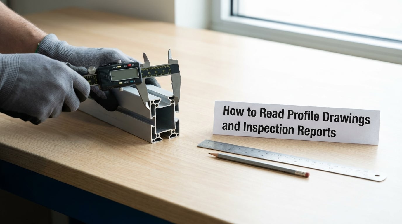
Six details decide whether a drawing is workable:
- The datum. A form tolerance such as straightness only means something relative to a reference. Say what the profile is sitting on and which face is the base.
- The units and decimals. 50.00 mm and 50.0 mm are not the same requirement, and the difference is often a mistake rather than a decision.
- The reference to a standard. Write the standard number and edition plus alloy and temper, as in “EN AW-6063 T6, tolerances per EN 755-9”. “Tolerance as per standard” leaves acceptance open to dispute because the characteristic was never named.
- Measurement conditions. Say whether dimensions are taken at room temperature and whether along the length or across the section. Aluminum moves about 1.8 mm per metre between 20°C and 100°C, so a hot part checked cold will read short.
- Sampling. Parts per lot, positions along the length, and how many pieces are measured.
- The difference between nominal, target and as-measured. Nominal is what you asked for. Target is where the extruder aims. As-measured is one reading on one part. Only the third one decides acceptance.
Inspection instruments differ too. Vernier calipers are fine for a rough check and poor for a 0.05 mm dispute; a micrometer, a profile gauge or a coordinate measuring machine gives repeatable answers. For tight features and sampling plans that matter commercially, name the instrument class in the order.
What Is the Right Tolerance for a Critical Feature?
The right tolerance is the tightest one the function actually requires, not the tightest one anyone can quote. Practitioners who work with extrusion daily say this constantly, and the discipline is simple: specify the tolerance the design needs, not the tolerance the catalogue offers.
Four levels cover most work:
- Standard. The published band from EN 755-9 or ASTM B221. This is the default for everything cosmetic and non-functional.
- Functional. A tightened band on the two or three dimensions that actually mate, sealing or carry load.
- Special. Agreed case by case with the extruder, normally before the die is cut, because it may force slower line speed and additional die correction.
- Machined. A feature held to a machining tolerance after extrusion, which is the right answer far more often than buyers expect.
When machining beats over-specifying
If a feature needs ±0.05 mm, a precise bore or a flat mounting face, buying the whole profile to that standard is the expensive route. Buy the extrusion at standard tolerance, leave machining stock, and cut the feature. The rule of thumb most shops use: anything tighter than roughly ±0.1 mm on a feature under 25 mm belongs on a machining operation, not on the extrusion order.
Stack-up is where assemblies fail
Individual parts do not determine fit, the stack does. Consider two mating profiles, each with a 50.00 mm dimension at ±0.30 mm. Every part can pass inspection and the two still cannot close, because the worst-case combination is 50.30 against 49.70, a gap of 0.60 mm plus whatever clearance the joint needs.
| Feature | Nominal | Tolerance | Worst-case limit |
|---|---|---|---|
| Profile A slot width | 20.00 mm | ±0.20 mm | 19.80 / 20.20 mm |
| Profile B tongue thickness | 19.60 mm | ±0.20 mm | 19.40 / 19.80 mm |
| Worst-case clearance | 0.40 mm design | ±0.40 mm total | 0.00 mm minimum |
At worst case the joint binds. That is not a supplier defect; it is a tolerance allocation error, and it is caught during stack-up analysis or it is caught on the assembly floor. If the joint must close in all conditions, either tighten one feature or increase the nominal clearance.
How Do Material and Process Changes Affect Tolerances?
Material and finishing choices move the tolerance results around, sometimes in ways that surprise people at final assembly.
- Alloy and temper. The alloys used most for extrusion, 6060 and 6063 in the EN numbering and 6061 and 6063 in the ASTM numbering, fall into defined alloy groups, and the standard tabulates different bands per group. High-strength alloys are generally harder to hold because flow stresses are higher and the die wears faster.
- Section design. Uniform wall thickness is the single biggest lever you control. A profile whose walls vary widely will vary in tolerance and will show sink marks where the thick sections cool slower.
- Line speed and die temperature. Faster extrusion and a hotter die reduce dimensional stability. A precision profile is usually run slower and colder, at a cost in output per hour.
- Mill finish versus coating. Anodizing is not neutral. A 15 micrometre anodic layer does not grow entirely inward; roughly half grows outward, which adds about 7 to 8 micrometres per surface. On a slot dimension that is about 15 micrometres of lost clearance. Powder coat is thicker again, typically 60 to 120 micrometres, so undercuts and part-to-part variation in film thickness must be designed in. If a dimension is tight and the profile will be coated, state whether the dimension is measured before or after finishing.
- Heat treatment and aging. Aging after solution treatment produces a small, predictable dimensional change, but it happens after the die correction and must be included in the target.
What Causes Common Profile Tolerance Failures?
These symptoms show up on almost every receiving inspection. Knowing the likely cause tells you what evidence to ask for.
| Symptom | Likely cause | What to request |
|---|---|---|
| Bow or sag along the length | Residual stress from asymmetric cooling, quench method, or storage | Form tolerance per metre, plus how parts are racked on delivery |
| Twist | Unbalanced section, stretch and straightener settings | Twist value in degrees per metre |
| Wall thickness varies around the section | Die design and flow imbalance, or speed too high | Wall thickness minimum value, not an average |
| Bubbles or visible voids | Moisture or contamination in the billet | Defect rejection criteria, since no tolerance covers this |
| Die lines on the surface | Die condition or a damaged bearing | Cosmetic acceptance standard agreed in advance |
| Sink marks on wide faces | Thick section cooling slower than thin walls | Minimum wall thickness and fillet guidance |
| Dimensional drift across a batch | Die wear, temperature drift, or line-speed change | First-off approval plus periodic re-report |
| Parts pass inspection but will not assemble | Tolerance stack-up, not a manufacturing error | Joint clearance calculation and mating profile tolerances |
One more failure mode deserves its own note: a hole or slot that sits within tolerance but drifts along the length of the profile. If position matters, the tolerance must be stated per length, not just overall, or an accessory fitted at one end will not fit at the other.
Frequently Asked Questions
What are the standard tolerances for aluminum extrusion?
Standard aluminum extrusion tolerances run roughly ±0.1 to ±0.3 mm on most profile dimensions, widening with the size of the dimension and the profile’s circumscribing circle diameter. Hollow profiles and thin walls carry wider wall thickness bands, while form tolerances such as bow and twist are quoted per metre rather than as a fixed number. Always confirm the exact value against the standard and edition named on your drawing.
What are the ASTM standards for aluminum?
For extruded shapes the main ASTM document is B221, which covers dimensional tolerances for extruded bars, rods, wire, profiles and tube. It works alongside ANSI/ASME Y14.5 for the geometric language and ANSI H35.2 for standard dimensional tolerances by size. In Europe the equivalents are EN 755-9 for general engineered profiles and EN 12020-2 for precision profiles.
What is an open dimension in extrusion tolerances?
An open dimension is one measured across a void rather than through solid metal, such as the width of a slot, the gap between two ribs, or the inside diameter of a hollow section. Because material flows differently around an opening, open dimensions are normally given a wider tolerance than closed or solid dimensions of the same nominal size. If a slot carries a sliding fit, state it explicitly.
What are the most common defects found in aluminum extrusion?
The recurring defects are bowing and twisting from residual stress, uneven wall thickness, bubbles and voids, visible die lines, sink marks on wide faces, discoloration from poor cooling, and dimensional drift across a batch as the die wears. Surface appearance defects are not covered by dimensional tolerance at all, so a cosmetic acceptance standard needs to be agreed in writing before production.
What are the key differences between the 2020 and 4040 aluminum extrusion profiles?
Both use a 20 mm grid, but 4040 has a wider face and a larger section, typically 40 by 40 mm, with a higher load capacity per length. That difference drives tolerance: the 2020 section has less material to carry flow, so its outer dimensions are usually held to a tighter absolute band than the 4040. Both are specified to the same family of standards, so check the published band for each size rather than assuming one covers the other.
Does anodizing change extrusion tolerances?
Yes, and in a predictable direction. A typical 15 micrometre anodic layer grows about half inward and half outward, adding roughly 7 to 8 micrometres per surface and therefore about 15 micrometres across a two-surface dimension. Powder coating adds more, commonly 60 to 120 micrometres. If a fit dimension is tight, say on the drawing whether it applies before or after finishing.
Conclusion: Start With the Critical Dimensions
Getting profile extrusion tolerances explained properly comes down to four actions. Find the dimensions that actually mate, seal or carry load. Write the standard number and edition on the drawing instead of a vague note. State the measurement conditions and instrument, including whether dimensions are taken before or after finishing. Then check that the extruder’s capability is tighter than the limits you wrote, and validate it on a first-off article.
Everything else can sit at standard tolerance, which is both cheaper and more honest. This guide reflects what is published in the standards and in common industry practice; the official documents govern contractual values, so confirm any number you put on a purchase order against the standard you name.
Updated for 2026.