
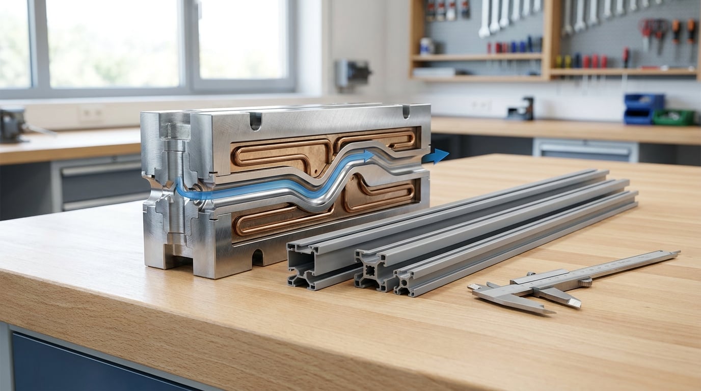
Extrusion die design basics come down to one idea: a forming die has to deliver the melt to every part of the profile opening at the same speed, the same temperature and the same pressure. The opening gives the shape; the channel layout, land lengths, thermal control and clearances decide whether the part comes off the line straight, dimensionally repeatable and free of surface defects. Get the concept wrong and you pay for it in short shots, curl, visible weld lines and a tool that never leaves the trial stage.
This guide is for the engineers who have to answer a simple, expensive question before anyone cuts steel: can this profile be extruded, and if so, what should the die look like?
Table of Contents
- What Is Extrusion Die Design?
- The Main Inputs That Shape Die Design
- How Material Flow Affects the Die
- Extrusion Die Design Basics for Channel Layout
- How to Choose Die Materials and Construction
- How Cooling and Thermal Control Change the Design
- How to Set Dimensions, Tolerances, and Die Clearance
- A Practical Workflow for Designing an Extrusion Die
- Common Die Design Mistakes and Defects
- How to Validate and Maintain the Die
- Frequently Asked Questions
- Do I need a custom extrusion die for every new plastic profile?
- Is flow simulation worth the time before a die is machined?
- How do I tell whether a defect comes from the die or from the process?
- Should the die be lubricated or coated?
- When should an extrusion die be repaired instead of replaced?
- Why do my extrudate dimensions change between production runs?
- Conclusion
What Is Extrusion Die Design?
Extrusion die design is the engineering of the flow path inside a forming tool so that a molten thermoplastic leaves it uniformly, which is what determines part size, surface quality, weight per metre and how stable the process runs hour after hour.
In practice the die is one element in a chain. An extruder melts and pressurises the resin and delivers a controlled flow. A feed block or transition directs that melt into the die. The die itself forms the cross-section. Downstream, a haul-off, a vacuum box or calibrator, a cooling tank and a cut-off or coiler turn the extrudate into a length of finished profile.
Four outputs follow from the tool design, and buyers evaluate every one of them:
- Profile geometry and dimensional repeatability along the length
- Surface quality, including gloss, weld lines and die lines
- Weight per metre, which is set by how much metal-like volume the die admits
- Production rate, meaning whether the profile can be run at the throughput the business case assumed
The die also decides whether a profile is manufacturable at all. Some shapes that look reasonable on a drawing simply cannot be filled and released at the same rate, and no amount of process adjustment rescues them.
The Main Inputs That Shape Die Design
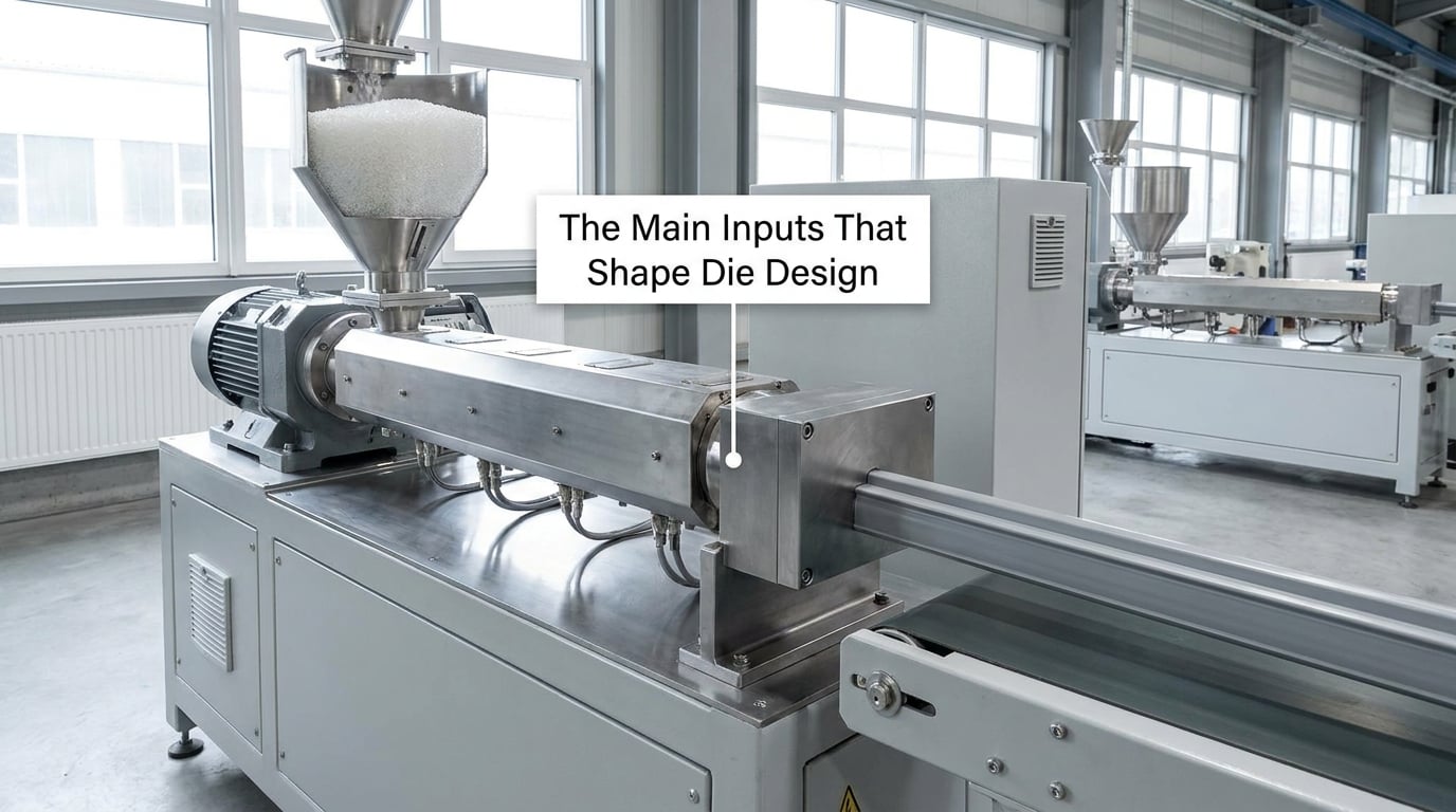
The die concept comes first, and the machining comes second. These inputs are what the concept is built from.
Resin rheology. Most thermoplastics shear-thin, so viscosity falls as shear rate rises. That single fact explains why a narrow, thick section and a wide, thin section in the same part do not fill the same way, and why temperature alone rarely fixes a balance problem.
Melt temperature window. Every resin has a processing range with a soft end and a degradation end. The die must deliver melt that is fluid enough to fill fine detail without pushing the material toward thermal degradation.
Throughput. Output in kilograms per hour sets the shear rate and therefore the pressure the die must carry. Doubling the rate roughly quadruples the pressure drop through a given flow path, so a die that ran comfortably at one output may be stressed well past its design point at two.
Profile size and tolerance. Large cross-sections, thin walls and tight tolerances drive different tool sizes and different correction strategies. Tolerance in particular decides how much room the die needs to absorb through flow balancing before a feature has to be machined later.
Cooling requirement. How much shrinkage the material has, how fast the line must run and how much space the downstream equipment leaves all set how hard the die has to fight cooling-induced distortion.
Feed shape and downstream equipment. A circular or rectangular feed block from a single-screw extruder does not suit every profile, and a profile that will not fit an available vacuum box or calibrator needs to be shaped around that constraint rather than argued with it.
Service conditions. Food contact, medical use, outdoor UV exposure, elevated temperature in service and cleaning regimes all change material choice and surface finish decisions.
How Material Flow Affects the Die
Metal-like flow in plastic extrusion obeys the same basic rule as any viscous fluid in a passage: the path of least resistance takes the most material. A profile section that offers a wider, shallower route to the exit than its neighbour fills faster and runs faster, and the mismatch shows up in the finished part.
Along the flow path, several things happen in sequence. Pressure builds as the melt is compressed through the converging entry and distribution areas. Shear at the wall generates heat, which raises the local melt temperature and lowers local viscosity. Weld lines form where separated flow fronts meet and have not fully interdiffused. Residence time measures how long a given parcel of material spends inside the tool.
Uneven flow causes the defects that generate most trial time:
- Uneven wall thickness along the profile
- Bow, twist and sag as fast-cooling and slow-cooling sections pull against each other
- Poor corner fill, where the melt reaches the corner late and cools before it can fill
- Visible weld lines and reduced impact strength across them
- Uneven die pressure, which shows up as surging, pulsating output and a length that varies from run to run
This is also why flow behaviour is press-specific and resin-specific. A design that runs smoothly on one machine can behave differently on another with a different screw and drive control, so die design and process design have to stay together.
Extrusion Die Design Basics for Channel Layout
The layout is the die. Once the profile is drawn, the work is arranging passages so every exit edge sees the same conditions.
How the melt enters the tool
The entry should let material into the flow area smoothly, without a step that traps material and degrades it. Abrupt contractions create dead zones, and dead zones create degraded polymer that later shows up as black specks or streaks. A generous, blended entry is cheaper than troubleshooting contamination.
Land length is the main flow-control lever
The land, or bearing, is the straight parallel section where the melt has fully filled the passage before it exits. Longer land on a given area adds resistance and slows that part of the flow, which thins the corresponding wall. Shorter land speeds it up and thickens that wall.
In practice, flow balancing is mostly a land adjustment. The thick, slow-moving areas get more land, the thin fast-running areas get less. Designers adjust in small steps because the relationship is nonlinear, and a change at one point disturbs the balance at the next.
Balancing corners, webs and thin walls
Corners are the classic weak point because the melt has to turn through the tightest path in the profile. Radiused corners fill better than sharp ones and give the tool a land to work with. Thin webs and long flat faces drift the other way and usually need their lands shortened.
Where a flow split must be divided and later rejoined, a bridge or feeder plate steers the streams back together and leaves a seam behind it. Those seams are the weld lines, and their placement is a design decision rather than a defect, because the location is chosen so the weakest line avoids the highest stress in the finished part.
How to Choose Die Materials and Construction
Die material selection is a trade between hardness, dimensional stability and the ability to repair or re-machine the tool later.
| Option | Strengths | Limits |
|---|---|---|
| Hardened tool steel | High wear resistance, stable dimensions, well-understood machining and EDM practice | Low thermal conductivity relative to softer alloys, so heat control depends on design |
| Corrosion-resistant tool steel | Better where moisture, aggressive regrind or corrosive additives are present | Generally lower wear resistance than the hardest tool steels |
| Surface-treated or plated steel | Protects detail features and reduces galling on fine profiles | Adds a re-coating step over the life of the tool |
| Cast or composite construction | Allows complex internal cooling passages and larger tools | More expensive to repair and re-machine; needs careful rework planning |
Beyond the base material, surface engineering does much of the life-extension work. Nitriding gives a hard, low-friction skin that resists wear and galling on high-output runs. Hardfacing or a wear-resistant insert on high-shear detail areas preserves the geometry that matters most. Wire EDM is the usual route for accurate internal cavities and pockets, combined with CNC milling for the entry and external features.
How Cooling and Thermal Control Change the Design
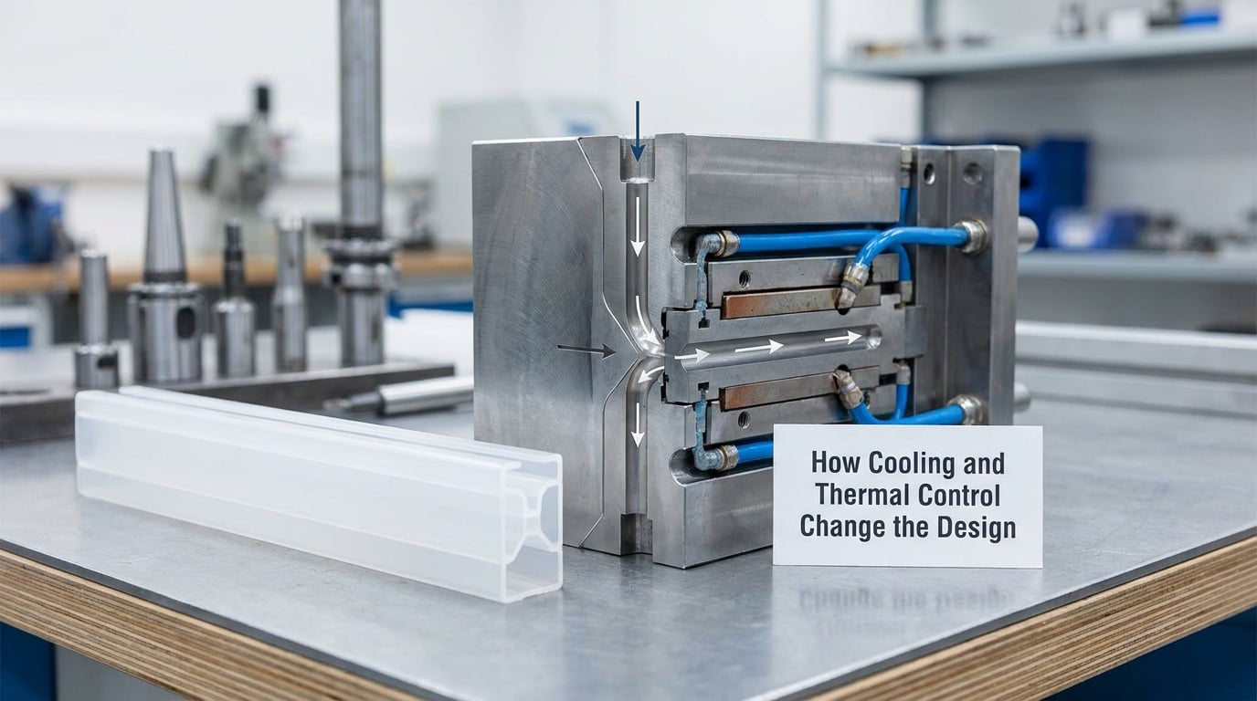
Die temperature decides melt viscosity, surface quality and how closely the running part follows the opening, and controlling it is a design task rather than a setting to be adjusted later.
Two different things are often confused. Die heating controls the melt while it is inside the tool: keeping the flow area warm fills corners and detail and hides weld lines, and running the die cooler stiffens the extrudate so it can hold its shape further downstream. Part cooling happens after the die, in a tank or air stream, and it is where final dimensional change mostly occurs.
That drives the layout. Heat has to reach the flow area evenly, which is why internal heater passages or cartridge and cartridge-block heating are arranged around the cavity rather than on one face. A die that heats unevenly produces uneven flow, and uneven flow shows up as a profile that is straight at the start of a run and drifts as the tool warms up.
Where part cooling is the dominant problem, more heat-transfer surface helps: fins on hollow profiles, more surface on thin sections, and vacuum in the downstream box where the profile needs to be drawn onto a calibrator. Hot runner and insulated tooling are useful for long runs with frequent stops, where reheating time would otherwise become the bottleneck.
How to Set Dimensions, Tolerances, and Die Clearance
Nominal die dimensions are never the finished part dimensions, because the extrudate swells on exit and then draws down as it cools.
The sequence is straightforward. The extrudate leaves the die and expands, which is die swell. Further along the line, tensile drawing thins it. Thermal contraction of the profile as it cools sets the final dimension. So the opening is cut oversize and the design target is the finished part, with the difference accounted for through trials.
Thermal growth of the tool itself adds to this. A die running well above ambient grows, and a dimension held to tight tolerance at start-up will not hold it at steady state. On large tools this is not a rounding error, so designers either specify the steel deliberately or accept a wider tolerance band and correct on a per-run basis.
Set achievable tolerances rather than ideal ones. Wall thickness, straightness, twist and flatness all depend on flow balance and cooling and belong in a realistic band. Where a feature must be held far tighter, move it off the extrusion tolerance entirely and machine it afterwards. Extruded dimensions and CNC-machined dimensions are held to completely different standards, and mixing the two on one drawing is a reliable way to a rejected part.
Clearances for sliding and core components need the same realism. Include thermal growth and wear in the running clearance, not just the nominal offset.
A Practical Workflow for Designing an Extrusion Die
A workable sequence keeps the toolroom and the press team in the loop, because the die cannot be designed well in isolation from the line.
- Define the product. Lock the finished part drawing, the cross-section, the alloy or resin grade, the mechanical requirements and the annual volume.
- Select and characterise the material. Get viscosity and rheology data for the actual grade, plus its shrinkage and thermal behaviour.
- Review extrudability. Check minimum wall thicknesses, corner radii, aspect ratios and features that cannot be filled reliably.
- Set the flow concept. Choose solid, hollow or multi-cavity architecture, then balance flow by adjusting lands, entry geometry and bridges.
- Simulate where it pays. Run filling and flow analysis for complex sections, thin webs or deep cavities before committing steel.
- Design the thermal system. Place heating passages and cooling surfaces for even tool temperature, and check wall thickness around passages.
- Machine, heat treat and finish. Machine rough, heat treat, then finish critical dimensions and surfaces, leaving stock for correction.
- Trial, measure, correct and release. Run production lengths, measure the profile against the drawing, re-machine the die where needed, then freeze and document the released tool.
The eighth step is the one that gets compressed, and it is the one that decides whether the first order ships on time.
Common Die Design Mistakes and Defects
Most extrusion problems are diagnosable from the symptom, because each one traces back to a specific design decision.
| Symptom | Likely cause | Corrective direction |
|---|---|---|
| Bow or twist in the cut length | Unbalanced flow or uneven cooling across the section | Rebalance lands and revise the cooling path; verify straightness along the length, not only at the cut |
| Walls thick on one side | Uneven flow distribution from entry to exit | Lengthen or shorten lands on the faster side; refine entry blending |
| Poor corner fill or rounded corners | Insufficient land at the corner or melt arriving late and cooling | Add corner land or radius, and check heat supply to that region |
| Visible seam line | Weld line left at a high-stress location | Relocate the flow split; adjust melt temperature and speed at the seam |
| Short shots, gaps or unfilled detail | Excessive pressure drop or a restricted final land | Reduce land on fine features, raise melt temperature within the resin window, or split the cavity |
| Surging and length variation | Die pressure too high for the drive control, or wear opening the flow area | Lower resistance through the tool and check wear pattern on the bearing surface |
| Die lines and gloss variation | Dies in the flow area, damaged surface, or residue build-up | Polish the flow area, clean between runs, inspect for adhered material |
The recurring design errors behind most of these are the same: walls that are too thin for the process, deep features that cannot be filled, sections that ignore downstream cooling, and drawings that specify extrusion-tight tolerance on features that should be machined.
How to Validate and Maintain the Die
A die is finished when it produces good parts, not when the steelwork is finished. That gap between machining and a usable tool is where most programme schedules are lost.
Validation starts with a full-length trial at production speed and rate. Measure wall thickness, opening dimensions, straightness, twist and flatness at several points along the length, because a profile that is correct at the die can still be wrong 30 metres later. Record melt temperature, tool temperature and pressure at each setting.
Correction follows the measurements. Where the error is a small, even offset, re-machining the flow area is usually cheaper and faster than fighting it with process settings, and most dies are deliberately finished with correction stock for exactly this. Where the error is a fill or balance problem, the answer is geometry, not a temperature tweak.
Between runs, clean the flow area rather than assuming it is fine. Adhered material changes the opening and the thermal balance in ways that look like a die fault. Inspect bearing surfaces for wear and galling, check heaters and thermocouples, and keep a record of which profile, resin and process settings the tool was released for. A die used on a second profile or a different resin is no longer the tool you qualified.
Frequently Asked Questions
Do I need a custom extrusion die for every new plastic profile?
Any profile that is not an existing catalogue shape needs its own die, because the opening is machined to that cross-section. Standard stock dies cannot be opened up, and a die is tied to the resin, the size and the conditions it was qualified on. The practical question is whether volume justifies it: low-volume work is often better served by a profile already run on an existing die, or by redesigning the part around a standard shape.
Is flow simulation worth the time before a die is machined?
It pays off most on complex profiles, deep cavities, thin webs and multi-cavity parts, where flow paths split, divide and rejoin and nobody can predict the balance by eye. Filling analysis highlights dead zones, short fills and weld line positions before steel is cut, and that costs a fraction of a trial cycle. Simple solid sections running at modest output rarely need it.
How do I tell whether a defect comes from the die or from the process?
Change something in the process first, then watch what happens. If the fault improves as melt temperature or output moves and the die pressure stays inside the expected range, you are looking at a process setting. If it moves with the profile geometry alone, at every setting, or if it worsens steadily over a production run, suspect the tool. Checking wall thickness along a single cut length tells you quickly whether the fault is even or varies with position.
Should the die be lubricated or coated?
Coating and surface treatment are routine: nitriding hardens the surface, and wear-resistant inserts protect high-shear detail areas on high-output work. Lubrication is a different question and depends on the resin, the tool temperature and whether the run is continuous. Apply release agents sparingly and check the supplier’s guidance, because excess agent on the flow area causes build-up and streaking.
When should an extrusion die be repaired instead of replaced?
Repair it when the opening is still correct and the problem is localised, such as damaged detail geometry, a cracked heater block or worn fastener bores. Re-machining to add correction stock is a normal, planned part of die life rather than an exception. Replace the tool when the flow area has worn beyond dimensional capability, when repeated corrections have moved the geometry away from the qualified design, or when the profile itself has changed.
Why do my extrudate dimensions change between production runs?
Most often the tool temperature differs. A die that starts cold fills differently from the same die at steady state, and the profile moves as the tool warms up over the first part of a run. Melt temperature and rate variation, resin lot differences and uneven cooling downstream all add to it. Log tool and melt temperatures with the first-off measurements so the drift can be separated from genuine dimensional change.
Conclusion
The principle that carries through every part of extrusion die design is uniformity: one melt, one flow rate, one temperature, one opening. Everything else in the tool exists to deliver it.
So the first actions are unglamorous. Fix the finished part requirements and the resin grade, obtain rheology and shrinkage data for that actual material, check the section for walls and features that can be filled, balance the flow paths using lands and entry geometry, design the thermal system around even tool temperature, and set tolerances that extrusion can actually hold. Then machine with correction stock left in, run a full trial, measure along the length, and correct the die from the measurements rather than from opinion. That is what turns a drawing into a die that makes the same part tomorrow.