
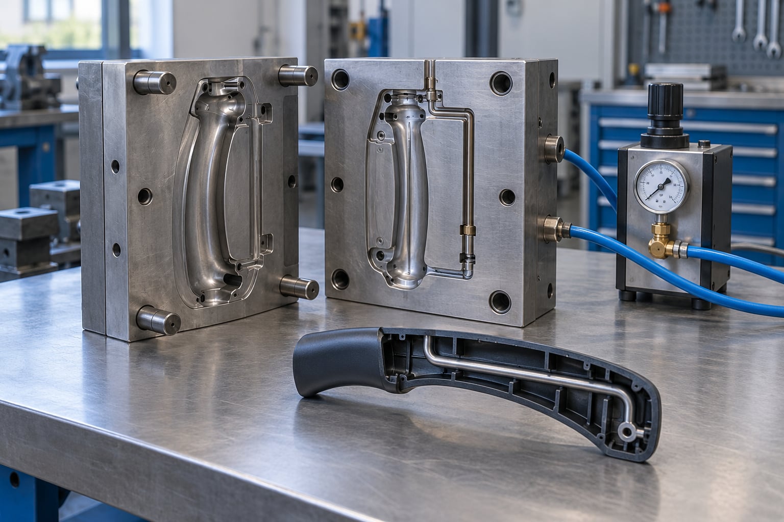
Gas assisted injection molding is an injection molding process variant in which pressurized nitrogen gas is injected into the partially filled mold cavity, hollowing out the core of thick sections while holding pressure against the walls through cooling. The result is a lighter, stiffer part with no sink marks. This guide walks through how the process works, what it costs you in tooling, and where it goes wrong.
If you have ever molded a handle, a rail or a ribbed housing in conventional injection molding, you already know the problem this process exists to solve. A thick section cools slowly, shrinks unevenly, and shows a sink mark on the surface anyone can see. More resin and more clamp force do not fix it. Gas does.
The rest of this page covers the process in order, then the parameter ranges, the parts that suit it, the defects that show up in production, and an honest look at when the extra tooling and equipment are not worth it. Gas assisted injection molding explained properly means knowing the disqualifiers as well as the benefits.
Table of Contents
- What Is Gas Assisted Injection Molding?
- How Does Gas Assisted Injection Molding Work?
- Gas Assisted Injection Molding at a Glance
- What Are the Benefits of Gas Assisted Injection Molding?
- Which Parts Are Best Suited to Gas-Assisted Molding?
- What Materials and Equipment Are Used?
- How Is the Gas-Assisted Process Controlled in Production?
- What Design Rules Improve the Result?
- What Are the Common Defects and Causes?
- How Does Gas-Assisted Molding Affect Cost and Quality?
- Frequently Asked Questions
- Which gas is used in gas assisted injection molding?
- How much material can gas assist save?
- What gas pressure is used in gas assisted injection molding?
- What parts are best suited for gas assisted injection molding?
- What causes gas breakthrough or fingering?
- Is gas-assisted injection molding more expensive than conventional molding?
What Is Gas Assisted Injection Molding?
Gas assisted injection molding is a process variant in which high-pressure nitrogen is injected into molten plastic inside a closed mold, forming a hollow internal channel through thick sections and pushing the surrounding melt outward to complete the fill. Because the gas is inert and the channel replaces solid resin, the finished part uses less material, cools faster and holds its shape better than a solid equivalent.
Conventional injection molding fills the cavity completely with plastic, then uses screw packing pressure to push more material in while the part cools. That works until the part gets thick. Molten plastic is a poor hydraulic fluid: across a section 150 mm from the gate, screw packing pressure might only deliver 15 to 20 percent of its set value. Nitrogen at high pressure has almost no pressure drop over that distance, so it reaches the far end of a part as effectively as the near end. That single difference explains nearly every benefit that follows.
The gas is always nitrogen. It is inert, non-flammable, inexpensive, and will not react with the polymer or degrade it. Air and carbon dioxide are not used in production molding for obvious reasons. The process is defined and standardized under ISO 20421-1:2019, which covers terminology and the basic process principles.
The result of a well-run gas-assisted part is a solid outer skin with a hollow core inside it. Cross-section one and you can see the channel clearly, which is why cross-section cutting, X-ray and ultrasonic inspection are all normal quality checks on this process.
How Does Gas Assisted Injection Molding Work?
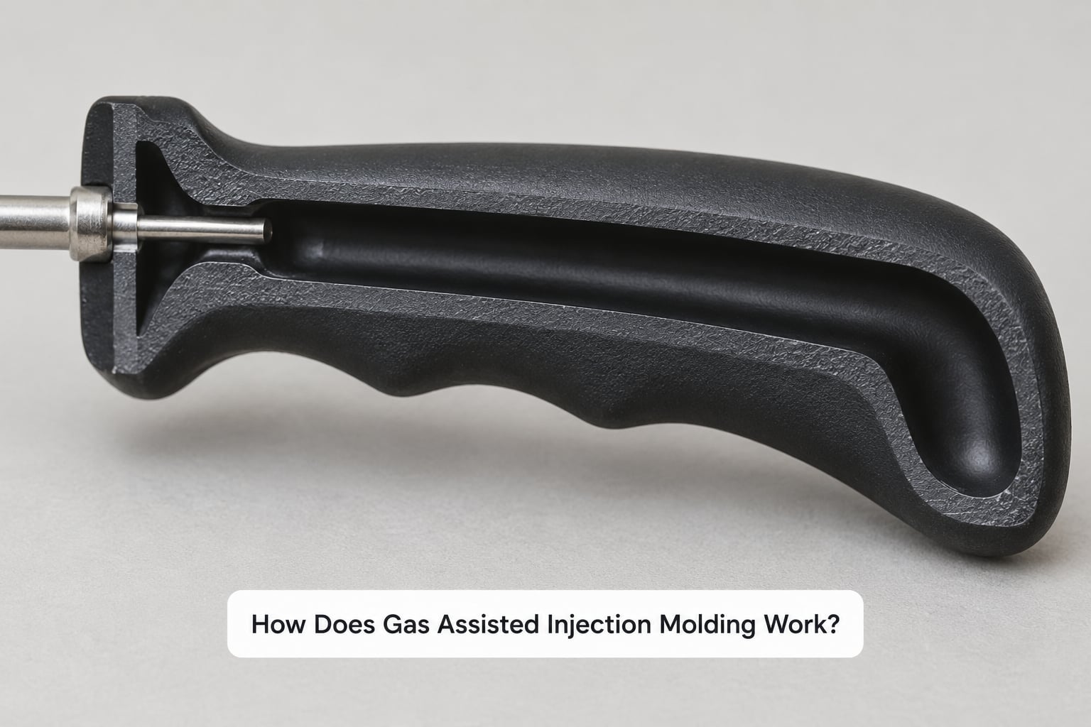
The short-shot method is the variant most people mean when they hear the term, and it is the one described below. The full-shot and spill variants work differently and are covered further down.
| Stage | What happens | What has to be controlled |
|---|---|---|
| 1. Clamping and preparation | The mold closes and clamps. Nitrogen lines, gas pins and any gas evacuation system are checked for leaks and valve function. | Clamp force, leak test pressure, gas pin retraction timing |
| 2. Plasticizing and short-shot fill | The screw melts and injects only part of the cavity volume, typically 70 to 85 percent, leaving the thick sections unfilled. This is deliberately a short shot. | Barrel and melt temperature, injection speed, shot volume, screw position |
| 3. Gas delay | Nothing happens for a set moment after the melt stops. This pause lets the melt skin form and set slightly, which is what stops the gas blowing the part apart. | Gas delay time, typically 0.5 to 3.0 seconds |
| 4. Gas injection | Nitrogen enters through a gas pin at high pressure, following the path of least resistance through the molten core and pushing plastic into the unfilled portions of the cavity. | Initial gas pressure, gas injection time, gas flow rate |
| 5. Gas hold and packing | Gas pressure is held and often stepped down, continuing to pack the walls against the mold while the plastic cools and solidifies. | Hold pressure profile, hold time, part temperature at vent |
| 6. Gas evacuation | Once the part is rigid enough not to deform, the gas is vented through the overflow region or evacuated, and the mold opens. | Vent timing, evacuation completeness, overflow well sizing |
| 7. Ejection and cooling | The part is ejected and finishes cooling outside the mold, where the much thinner walls now release heat far faster than a solid section would. | Ejection temperature, cooling medium, cycle time |
Two details in that table cause most of the confusion for newcomers. First, the short shot is not a mistake; an under-filled cavity is the entire point, because it leaves a molten core for the gas to travel through. Second, the gas does not fill a pre-made cavity. It displaces melt as it goes, and the shape of the channel is determined by where the gas chose to travel.
Why nitrogen does what packing pressure cannot
Think of the short shot as a channel of hot plastic running from the gate to the thick section. Screw packing pressure has to push through that plastic, and molten polymer resists flow heavily. Nitrogen does not have to push through anything, because the gas is injected into the channel core and moves ahead of the melt instead of through it.
Cooling time is the other place the physics pays off. Cooling time scales roughly with the square of wall thickness: a 2 mm wall needs roughly 5 to 8 seconds to cool, while a 20 mm section can take 8 to 12 minutes. A gas-assisted section often behaves like a 3 mm wall wrapped around a void, so the cooling time drops accordingly.
Gas Assisted Injection Molding at a Glance
Three processes get compared constantly in sourcing conversations, and the differences between them are practical rather than theoretical.
| Characteristic | Conventional injection molding | Gas-assisted injection molding | Structural foam molding |
|---|---|---|---|
| Cavity pressure | Highest; full cavity pressure throughout fill and pack | Lower; gas pressure replaces much of the packing force | Moderate; controlled by chemical blowing agent expansion |
| Material usage | 100 percent of nominal cavity volume | Typically 20 to 40 percent less resin per part | Roughly 15 to 25 percent less, thin solid skin over a foamed core |
| Part weight | Baseline | Noticeably lighter, controlled by the gas channel volume | Lightest of the three, but core strength drops |
| Cooling time | Long for thick sections, driven by wall thickness squared | Roughly 40 to 60 percent shorter in many parts | Short; the foamed core conducts heat poorly |
| Surface finish | Good, can reach class A with good tooling | Good; class A is achievable with careful gas pin placement | Textured skin; fine cosmetic surfaces are difficult |
| Sink marks | Common in thick sections | Largely eliminated | Eliminates sink marks by design |
| Tooling and equipment | Standard molding machine, simplest tooling | Gas control unit, gas pins, venting, sometimes evacuation | Standard tooling plus modified screw and control |
| Typical part | Thin-walled housings, containers, general components | Handles, rails, frames, ribbed panels, structural shells | Enclosures, pallets, panels where weight beats cosmetics |
Structural foam is cheaper to run and lighter still, but the surface is textured and the core has less strength, so it is rarely the answer when the part is handled or seen. Gas assist keeps a solid skin, which is why it wins in automotive and appliance work where both appearance and stiffness matter.
What Are the Benefits of Gas Assisted Injection Molding?
- Less material per part. The realistic figure is 20 to 40 percent, not the 70 percent that turns up in some marketing copy. A hollow core in a thick handle removes resin where it was doing no structural work anyway.
- No sink marks. The gas holds pressure inside the section while the skin solidifies, so the surface stays flat. This is the benefit that most often converts a project.
- Shorter cooling and cycle time. Because cooling scales with the square of wall thickness, thinning the effective section pays twice. One of our recurring clients cut a 42 second cycle on an ABS grab handle purely by hollowing the section. If your program is cycle-time constrained, our guide to reducing injection molding cycle time is worth reading alongside this one.
- Better stiffness-to-weight. Material placed at the outer surface does far more for bending stiffness than the same material buried in the middle. A hollow section of the same weight bends considerably stiffer.
- Long flow paths in big parts. Gas can push melt a long way from the gate without the pressure loss that limits conventional filling, which is how large panels get filled evenly.
- Fewer parts to assemble. Handles, inserts and structural ribs can be molded integrally instead of being assembled or welded afterwards.
- Lower clamp force and longer tool life. With less cavity pressure to fight, the clamp tonnage requirement drops, and a mold that runs at a lower fraction of its rating wears more slowly. That is also why gas-assist parts intersect the topic of preventing flash in injection molding, since flash is one of the failure modes when gas pressure is set too high for a given wall.
- Better dimensional stability. Uniform pressure at any distance from the gate means uniform shrinkage, so large parts warp less and hold tolerance more reliably.
Which Parts Are Best Suited to Gas-Assisted Molding?
The parts that benefit most share one feature: a thick section that conventional molding cannot pack evenly. Long tubes, deep ribs, bulky handles and frames all qualify.
- Automotive grab handles and door handles. Long, thick-walled and cosmetic. A handle is the textbook case because a solid version sinks and a hollow version does not.
- Roof rails, side rails and structural rails. Long flow paths where gas pressure travels further than packing pressure can.
- Instrument panel carriers and dashboard structures. Thick, ribbed, and prone to warpage in solid form.
- Appliance handles and frames. Visible, touched, and usually molded in ABS or polypropylene.
- Chair armrests, furniture frames and tubular legs. Consolidate several parts into one and cut both weight and assembly steps.
- Television bezels, monitor frames and housings. Large flat parts with thick edges, where warpage is the recurring complaint.
- Medical device housings and pump or manifold covers. Where a hollow channel must not trap fluid, a designed channel with controlled venting is safer than a blind cavity.
- Pallets and large structural containers. Very large sections where solid molding would be uneconomic in both resin and cycle time.
When gas assist is the wrong answer
Being straight about this is more useful than another benefit list. Gas assist costs more in tooling and equipment, and it adds controls a conventional tool does not need. It is the wrong choice when:
- Wall thickness is uniform and below about 3 mm. There is no thick section to hollow, so the gas has nothing to do.
- The part is transparent or tinted. The hollow core makes light transmission uneven and optical parts usually need a solid wall.
- The part needs a class A cosmetic surface and the gas pin would land on a visible face. It can be engineered around, but it costs design freedom.
- Annual volume is low. Below roughly 100,000 parts a year, the tooling premium of about 15 to 30 percent over conventional tooling is hard to recover.
- Part weight is under about 50 g. The savings are proportionally small and rarely pay for the added complexity.
- The polymer is a poor fit. Highly fiber-filled grades and liquid crystal polymers behave unpredictably around a moving gas front.
What Materials and Equipment Are Used?
Material choice matters more here than in conventional molding, because the gas front depends on how the melt flows. Semi-crystalline polymers and amorphous grades do not behave the same way.
Materials that work well
Polypropylene and HDPE are the most common choices: excellent flow, forgiving gas penetration, and a good balance of stiffness and cost. ABS and PC/ABS mold well and give a good cosmetic skin. Polyamides (nylon) are widely used in automotive structural parts, though the glass-filled grades need more care with gas timing.
Materials that need adjustment
Polycarbonate flows differently and is sensitive to the gas front, so delay time and pressure step-downs are usually tuned more conservatively. Acetal (POM) has poor melt strength at gas temperatures and needs careful parameter control. Glass-filled grades of any resin flow anisotropically around the hollow core, and the fill pattern has to be validated in mold flow analysis before cutting steel.
Materials to avoid or treat carefully
Thermoplastic elastomers and TPU are difficult: they are soft, they gasify at melt temperature, and the hollow core collapses easily. Liquid crystal polymers are strongly anisotropic, so the channel position and the fiber orientation must be designed together. Structural foams and low-density grades can blow through unpredictably.
Equipment
Beyond a capable injection molding machine, you need a gas control unit (a pressure vessel with a pressure regulator, a fast valve, and a pressure decay or hold profile), a nitrogen supply of at least 99.5 percent purity, gas pins mounted through the mold, venting and overflow regions at the end of the channel, and a way to evacuate gas on cycles where the part will not vent cleanly. Nitrogen is usually supplied by a pressure swing adsorption or membrane generator on site rather than in bulk cylinders.
Moisture content in the resin matters more than usual, because water vapor mixes with the injected nitrogen and expands. Purity matters too: nitrogen above roughly 0.5 percent oxygen can cause internal burn marks along the channel surface. Both are reasons the gas supply and the dryer are part of the process specification, not an afterthought.
How Is the Gas-Assisted Process Controlled in Production?
Gas-assisted molding has more independent variables than conventional molding, which is why a trial and a process sheet matter so much. The ranges below are typical starting windows for a well-behaved part, not universal setpoints.
| Parameter | Typical range | What it controls |
|---|---|---|
| Short-shot volume | 70 to 85 percent of cavity volume | How much melt is available for the gas to push and how thick the skin ends up |
| Initial gas pressure | 200 to 350 bar | Whether penetration reaches the end of the section |
| Hold gas pressure | 100 to 200 bar, often stepped down | Wall packing through the cooling phase |
| Gas delay time | 0.5 to 3.0 seconds | How much melt skin forms before the gas enters |
| Gas injection time | 1.0 to 5.0 seconds | Front speed and channel length reached |
| Gas hold time | 10 to 30 seconds | Packing duration through cooling |
| Nitrogen purity | 99.5 percent or better | Avoids internal burn marks |
| Melt temperature | Material and geometry specific | Flow and skin formation |
| Mold temperature | Tooled to the geometry | Cooling time and skin quality |
You will see lower gas pressure figures quoted in some sources, sometimes as low as 50 to 200 bar. The difference is not a contradiction: those ranges usually come from larger parts with longer channels and lower-viscosity melts, where a gentler front still reaches the end. A small handle in ABS often needs the higher end of the range to reach the far end before the melt freezes.
Troubleshooting starts with part weight, which is a cheap and surprisingly reliable indicator. Part weight varies with how much gas actually got inside. Weights wandering beyond plus or minus 1.5 percent across a batch usually mean inconsistent penetration, and that is faster to see than waiting for a dimensional report. The rest of the shop discipline matters just as much: a written process sheet, scheduled checks on the gas pins and vent paths, and a defined interval between cleanings. Our mold maintenance schedule guide for injection molding covers the intervals worth setting before a gas-assist tool ever runs.
What Design Rules Improve the Result?
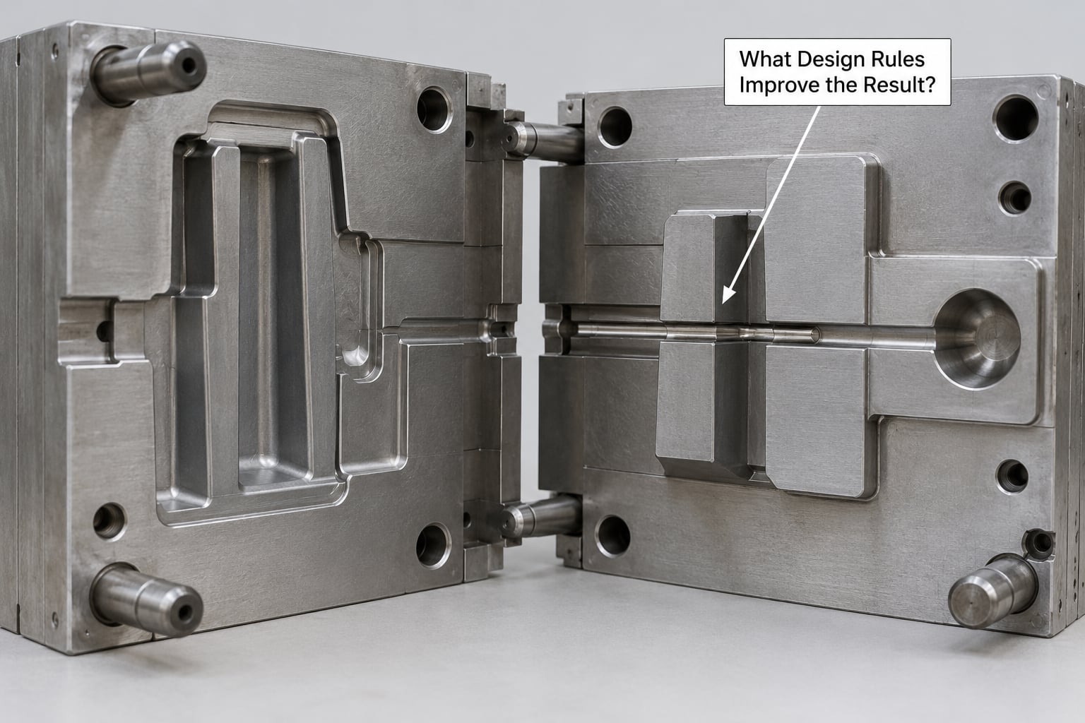
Balance the plastic and gas volumes
The short-shot volume and the channel volume are two halves of the same number. If the channel is too large for the gas to fill, you get an unfilled end; if it is too small, the gas has nowhere to go and pushes back against the melt. Run mold flow analysis before committing to steel, and expect to iterate at the T1 trial.
Size the channel to the wall
A common starting rule is a channel diameter of roughly two to three times the finished wall thickness. Bigger channels are lighter but leave a thinner skin and are more prone to breakthrough; smaller ones may not fill the section evenly.
Design the flow path
The gas follows the path of least resistance, so the channel should be a deliberate, continuous route from the gas pin to the end of the section. A channel that narrows and then opens again creates fingering, where the gas front splits and pushes through the wall. If the channel has to turn, widen it on the outside of the turn. Dead-end channels that the gas cannot fill are a common cause of under-packed tips.
Place the gas pin on a hidden face
The pin leaves a witness mark, typically 1.0 to 2.0 mm across, wherever it enters. Put it on a non-appearance surface, on a parting line, or use a retractable pin that pulls out before the gas is injected so no mark is left at all.
Manage wall transitions
Keep thick-to-thin wall ratios within about 2:1 to 4:1, and taper rather than step. Ribs are usually specified at a height-to-thickness ratio around 3:1, which keeps them thin enough to hollow. Avoid abrupt thick bosses next to thin walls; the gas front will find the thin section and blow through it instead of filling the boss.
Provide venting and an overflow well
The end of the channel needs somewhere to go. A spill well or overflow well receives the melt the gas displaces, and a vent lets the gas escape on the next stroke. A vent that is too small shows up as short shots; one that is too large shows up as flash at the vent itself, which is a different problem with a different fix.
Plan cooling and draft
Core cooling lines through the gas channel region matter more here than in a thin part, because you have designed the cooling around a void. Keep draft on all surfaces, and remember that the hollow section shrinks differently from the solid skin, so the gate and rib layout drive warpage more than in a conventional part.
What Are the Common Defects and Causes?
Every defect below has a characteristic appearance and a characteristic cause. The check in the last column is what confirms it, rather than a guess from the visual alone.
| Defect | What it looks like | Likely causes | How to confirm |
|---|---|---|---|
| Short shot | Unfilled end of the channel or an unfilled cavity corner | Gas delay too long, gas pressure too low, shot volume too high for the channel size | Cut a section; the channel ends short of the wall |
| Gas breakthrough or fingering | Gas splits through the wall, leaving a raised or blown mark on the surface | Wall too thin, skin too hot, gas pressure too high, hold pressure stepped down too fast | X-ray or cross-section; blow-through follows the thinnest path |
| Blistering | Surface blisters after the part has been out of the mold | Gas not fully vented, moisture in the resin, wall too thin to hold pressure | Weight plus surface check; a blister that appears days later points to trapped gas |
| Gas pin witness mark | Small circular imprint at the pin location | Pin placed on a visible surface, or not retracted before injection | Direct visual inspection under standard lighting |
| Internal burn marks | Brown or scorched streaks inside the channel surface | Nitrogen purity below specification, typically above 0.5 percent oxygen; or excessive pressure decay | Cross-section; check the gas supply purity reading |
| Under-packed channel | Dull, rough channel surface, part lighter than nominal, visible ripple marks | Hold pressure too low, hold time too short, gas injected too late | Part weight outside plus or minus 1.5 percent; rough channel surface on section |
| Sink marks | Localized depression on an outer surface | Usually the reverse case: gas did not reach that section, or the section is thicker than the channel | Check channel extent on a sectioned part |
| Weld lines | Visible seam lines where melt fronts met | Melt temperature, injection speed and venting at the meeting point, not the gas itself | Locate the seam relative to the fill pattern in the simulation |
| Warpage | Part bows or twists out of flat | Asymmetric skin thickness, uneven cooling, unbalanced rib layout, gas front ending off-center | Flatness measurement across a conditioned part |
| Delayed or stalled penetration | Channel forms partway and stops, tip is heavy and solid | Gas injection time too short, pressure too low, front slowed by a narrow channel section | Section the tip; the transition is usually at a channel narrowing |
How Does Gas-Assisted Molding Affect Cost and Quality?
The economic case is straightforward once you count everything. Gas assist adds cost to the tool and the machine, and it takes material, cycle time and scrap out of the per-part cost.
| Factor | Conventional molding | Gas-assisted molding |
|---|---|---|
| Tooling cost | Baseline | Typically 15 to 30 percent higher; gas pins, venting, overflow wells and possibly slide or retractable hardware |
| Equipment | Standard machine | Adds a gas control unit, gas supply, and machine capability for precise valve timing |
| Material cost per part | Baseline | Lower by the resin saved, often 20 to 40 percent |
| Cycle time | Baseline, limited by cooling of thick sections | Often materially shorter, so more output per hour from the same press |
| Scrap and rework | Higher where sink marks and warpage drive rejects | Lower, since the two most common cosmetic defects are designed out |
| Inspection | Dimensional and visual | Adds part weight monitoring, cross-section cutting on first articles, X-ray or ultrasonic checks on critical parts |
| Break-even | Not applicable | Generally favors parts above about 50 to 100 g and volumes above roughly 100,000 parts a year |
Quality risk is managed rather than eliminated. The process window is narrower than conventional molding, so process sheet discipline, nitrogen purity monitoring and moisture control are part of the production system, not troubleshooting steps you reach for later. A well-documented trial, a defined parameter window and a defined in-process check such as part weight are what separate a controlled gas-assist program from a supplier who got lucky on the first run.
One last practical note for buyers: ask any candidate supplier to show you a sectioned part from a production run, not a sample. The channel tells you more about process control than a polished surface does, and a well-run channel is even and consistent to the end of the section.
Frequently Asked Questions
Which gas is used in gas assisted injection molding?
Nitrogen is the only gas used in production gas-assisted injection molding. It is inert, non-flammable, cheap and will not react with or degrade the polymer. Commercial systems typically use 99.5 percent purity or better, supplied by a pressure swing adsorption or membrane generator on site. Purity matters practically: nitrogen above about 0.5 percent oxygen can leave internal burn marks along the gas channel surface.
How much material can gas assist save?
Realistic material savings run from 20 to 40 percent, not the 70 percent claimed in some marketing material. The figure depends on how much solid material you replace with the hollow channel. Thin-walled parts save very little, because there is little solid material to remove. Large thick-walled sections, where a 20 mm solid section becomes a 3 mm skin around a void, sit at the top of the range. The economic case usually needs part weights above roughly 50 to 100 g.
What gas pressure is used in gas assisted injection molding?
Initial gas pressure typically falls between 200 and 350 bar, with a hold pressure of 100 to 200 bar that is often stepped down through the cooling phase. Smaller parts in low-viscosity melts often need the higher end, while large parts with long channels can run at 50 to 200 bar. The figures you see quoted as contradictory usually come from different part sizes rather than from different physics. Timing values are equally important: 0.5 to 3.0 seconds of delay before gas injection.
What parts are best suited for gas assisted injection molding?
Parts with thick sections, long flow paths and a need for a good cosmetic surface. Typical examples are automotive grab handles and door handles, roof and side rails, instrument panel structures, appliance handles, chair armrests, television bezels, medical housings and large structural containers. The common thread is a section too thick for screw packing pressure to pack evenly. Thin-walled, transparent or low-volume parts are poor candidates.
What causes gas breakthrough or fingering?
Breakthrough and fingering both mean the gas front escaped through the wall rather than travelling along the channel. Causes include a wall that is too thin for the pressure being used, a skin that is still too hot, a channel that is too small or that narrows and widens, and a hold pressure that drops too quickly. A channel that changes direction needs to be widened on the outside of the turn. A cross-section or X-ray of the affected part confirms the diagnosis quickly.
Is gas-assisted injection molding more expensive than conventional molding?
The tooling typically costs 15 to 30 percent more and the machine needs a gas control unit, gas supply and precise valve timing. Those costs are offset by 20 to 40 percent less resin per part, a shorter cycle in many designs, and lower scrap now that sink marks and warpage are designed out. Above roughly 100,000 parts a year and above about 50 to 100 g of part weight, the case usually works. Below those thresholds, conventional molding is often the better answer.
If you are evaluating the process for a specific part, start by sectioning a current molded sample and measuring the thickest section. If that section is above about 4 mm and carries a sink mark, gas assist is worth a trial. If the walls are already uniform and thin, conventional molding with better packing and cooling is likely the smarter call.
When the trial does go ahead, insist on a documented parameter window and a sectioned first article. Those two artifacts tell you more about whether the process is under control than any capability presentation will.