
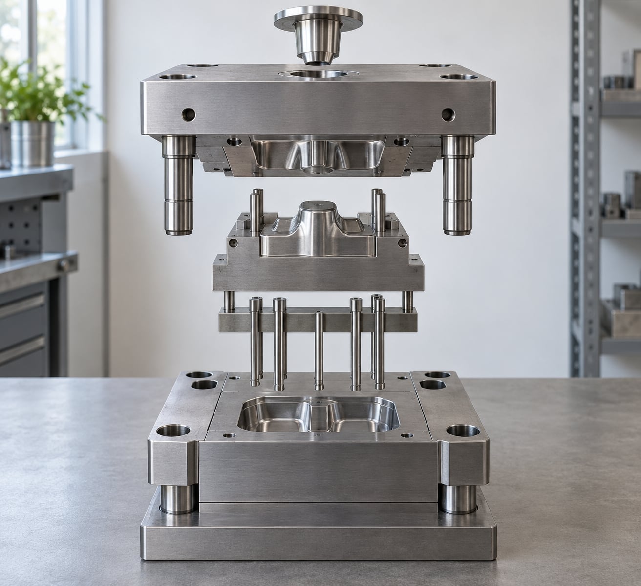
An injection mold is a hardened steel tool that receives molten plastic, shapes it, cools it, and releases a finished part on every cycle. It is built on a standard mold base and works through five functional systems: forming, gating, cooling, ejection, and the guiding and structural plates that hold everything in register.
There are around 12 core components you need to know, and each one maps to a specific stage of the cycle. Knowing which component does what also tells you where a defect comes from, which is the difference between a five-minute fix and a two-week wild goose chase.
The guide below walks through each part of an injection mold and its function in plain language, then shows how the pieces work together across a cycle.
Table of Contents
- Parts of an Injection Mold and Their Functions at a Glance
- 1. Injection Mold Base or Support Plates
- 2. Cavity Plate
- 3. Core Plate
- 4. Mold Cavity
- 5. Mold Core
- 6. Sprue Bushing and Sprue
- 7. Runner System
- 8. Gate and Gate Pin
- 9. Ejector System
- 10. Cooling Channels and Cooling Fittings
- 11. Vents and Vent Blocks
- 12. Mold Alignment, Guide Pins, and Return Pins
- Frequently Asked Questions
- What is the difference between the core and the cavity in an injection mold?
- What causes ejector pin marks on molded parts?
- Which parts of an injection mold wear out first?
- Can you make your own injection mold?
- What is the average lifespan of a plastic injection mold?
- How do I tell a mold part from a machine part?
- Conclusion
Parts of an Injection Mold and Their Functions at a Glance
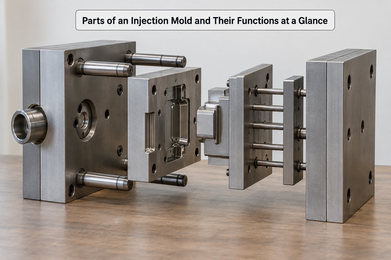
The table below lists each major component, what it does, and the cycle stage where it matters most.
| Component | Primary function | Where it matters in the cycle |
|---|---|---|
| Mold base / support plates | Carries clamping load and holds everything aligned | Mold open, clamping, mold close |
| Cavity plate | Holds the cavity-side tooling that forms the outside of the part | Fill, hold, cool |
| Core plate | Holds the core insert and core-side components | Fill, eject |
| Mold cavity | Defines external shape, texture and visible detail | Fill |
| Mold core | Forms holes, ribs, bosses, draft and undercuts | Fill and eject |
| Sprue bushing and sprue | Forms and seals the melt entry point from the nozzle | Injection start |
| Runner system | Distributes melt to every cavity | Fill |
| Gate / gate pin | Controls where and how fast melt enters the cavity | Fill |
| Ejector system | Removes the part and core features after cooling | Ejection |
| Cooling channels and fittings | Removes heat and holds mold temperature | Cool |
| Vents and vent blocks | Lets trapped air and gas escape | Fill |
| Guide posts, bushings and return pins | Align the halves and reset the ejector plate | Mold close and mold open |
Read down the third column and you can follow a single shot through the tool. The sprue bushing handles injection start, the runners and gate handle fill, the cooling channels handle the cool phase, and the ejector system handles mold open.
1. Injection Mold Base or Support Plates
The mold base is the steel framework that supports every other component and takes the clamping force. Without it, the mold would flex under injection pressure and parts would come out out of tolerance within a few thousand shots.
Toolrooms rarely cut a base from scratch. They buy a standard base from a supplier such as DME, HASCO or SPX and machine inserts into it, which is faster and cheaper than building the plate stack by hand. The main plates you will hear named are:
- A-plate (fixed platen): the plate bolted to the machine’s stationary platen, carrying the cavity plate and sprue bushing.
- B-plate (clamping or support plate): the thick plate behind the cavity plate that spreads load back to the platen.
- Cavity plate and core plate: the working plates that carry inserts and meet at the parting line.
- Ejector housing plate and support plate (moving side): carry the ejector assembly and take the return-pin impact.
- Spacer block: sets the overall mold thickness and takes side load when the halves close.
- Stripper plate: the plate that pulls the part off the core before ejector pins push it clear.
A locating ring machined into the center of the A-plate centers the whole mold on the machine platen. Get it wrong by a few millimeters and the melt never reaches the center of the cavity evenly.
Base steel choices follow the job. Pre-hardened P20 and 1.2311 work for short- to medium-run tools, while H13 (1.2344) and 1.2083 stainless get used for high-volume or high-temperature runs where heat and corrosion matter.
2. Cavity Plate
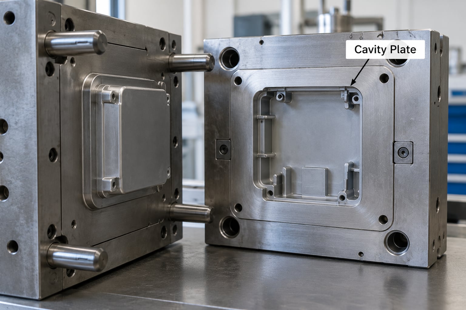
The cavity plate is the stationary-side plate that holds the cavity-side tooling, and it defines the outside dimensions, features and appearance of the molded part. Everything a customer sees when they look at the finished component comes off this side.
On a simple two-plate mold the cavity is machined directly into the face of the cavity plate. On most production tools the cavity is a separate insert bolted or screwed into that plate, so it can be replaced for retexturing or repair without buying a whole new base.
Cavity inserts are usually made from hardened stainless such as 1.2083 or 1.2316 when corrosion and polishing matter, or from hardened tool steel when the geometry is simple and the run is long. Surface finish is cut or polished directly on the insert, so the texture you specify on the cavity plate becomes the texture on the part.
3. Core Plate
The core plate is the moving-side plate that supports the core insert and positions everything on the core side of the parting line. It backs up the core so the two halves meet square under clamping load.
Most core inserts bolt or screw into the core plate from the parting-line face. That mounting method matters in practice: unscrewing the insert gives you access to the core geometry for EDM work or insert changes without stripping the whole mold.
The core plate also carries the elements that have to sit behind the part, including ejector bore holes, cooling fittings for the core, and the bushings for leader pins and return pins. Because it moves with the moving half, everything mounted in it moves as one rigid body during mold open and mold close.
4. Mold Cavity
The cavity is the negative space that receives the molten plastic, and it defines the part’s external shape, surface texture and visible detail. Think of it as a machined negative of the finished component.
Two rules govern cavity geometry. Draft of roughly one to three degrees on side walls lets the part release instead of dragging, and uniform wall thickness keeps the plastic flowing and cooling the same way across the whole surface.
Thick sections in the cavity create thick sections in the plastic, and thick plastic sections sink as they cool. That is the sink mark you see on a flat panel, and it comes straight back to how the cavity was designed rather than to anything the setter did.
5. Mold Core
The core is the set of projecting steel features that build holes, recesses, ribs, bosses and internal detail, and it is the part of the mold you can mostly see once the tool opens. It sits in the cavity when the halves close and defines everything the cavity cannot reach on its own.
Ribs, bosses and draft all live on the core. Ribs at roughly 60 percent of the nominal wall thickness are a common target because a full-thickness rib creates a local sink mark in the plastic above it.
Undercuts go one step further. When a feature locks the part into the cavity, the core brings in a side action: a slide that withdraws along the parting line, a lifter that pushes at an angle, or an angled pin that travels on its own path. Slides ride on wear plates and are driven by angled pins, which is why the core plate often carries angled-pin bores on its back face.
6. Sprue Bushing and Sprue
The sprue bushing is the hardened insert that the machine nozzle presses against, and it forms the actual entry passage into the mold. Everything the tool receives first passes through it.
Its job is to locate the nozzle concentrically, seal against the nozzle face so melt cannot escape backwards into the machine, and provide a wear-resistant surface that can be replaced when the nozzle has chewed it up.
Inside the bushing, the sprue is the tapered channel the plastic runs down on its way to the runners. Right where the sprue meets the runner system there is normally a cold slug well, a small blind pocket that catches the first, coldest, most contaminated melt and lets the machine push it out as a slug instead of into the part.
Confusing the sprue with the nozzle is the most common beginner mix-up on shop floors. The nozzle belongs to the machine and screws into the barrel. The sprue belongs to the mold and lives inside the sprue bushing.
7. Runner System
The runner system is the network of channels that carries molten plastic from the sprue to each cavity. Its job is to deliver the same fill to every cavity at the same time, because a cavity that fills last gets a different part than one that filled first.
A balanced runner treats all cavities as one symmetric system. If one cavity sits at the end of a longer branch, the branch is rebalanced or that cavity is repositioned, so the last-fill and first-fill cavities are within a few percent of each other.
Cold runners are the default: channels machined into the mold plates that solidify with the part and get pulled out as scrap. Hot runners keep the melt hot with a heated manifold and hot nozzles, so the only plastic that ends up in the box is the part itself.
| Factor | Cold runner | Hot runner |
|---|---|---|
| Tool cost | Lower | Higher, manifold and heaters add up |
| Runner scrap | Yes, per shot | None |
| Cycle time | Cooling time covers runner solidification | Can shorten the cycle |
| Gate vestige | Visible, often trimmed or cut off | Gate can be cut flush at the valve |
| Maintenance | Little to do | Heaters, thermocouples and valves to service |
| Color changes | Simple | More involved, purging and control settings |
The economics are straightforward. Hot runner systems pay back their extra tool cost through the volume of runner scrap they eliminate, which is why they show up on long automotive and packaging runs and rarely on short prototyping runs.
8. Gate and Gate Pin
The gate is the small opening through which melt enters the cavity, and it is the single most consequential decision in gating design because it sets the fill pattern, the weld line locations and the vestige you have to remove later.
A valve-pin gate uses a pin that opens and closes the gate on command. Sequential filling means the first cavity is filled and packed before the valve opens to the second, which lets a multi-cavity mold produce stable, fully packed parts. Simultaneous opening is faster but gives up some control over pack consistency.
| Gate type | Best use | Trade-off |
|---|---|---|
| Edge gate | Simple, low-cost, easy to machine | Large vestige, easy to see |
| Submarine gate | Automotive parts needing a clean surface | Runner must be cut off; long gate can drool |
| Pin gate | Small, precise parts and multi-cavity tools | No runner scrap, high tool cost |
| Fan or tab gate | Flat panels needing even fill | Wider gate is easier to degate |
| Tunnel gate | Long open flow path on sturdy parts | Requires careful parting-line shutoff |
| Valve gate | Hot runners, zero vestige, sequential fill | Maintenance on the valve and heater system |
Where the gate sits decides where the weld lines land. Two flow fronts that meet and fuse leave a visible seam, and on a cosmetic part that seam is often the thing the customer complains about first. On a structural part you orient the weld line to a rib or a corner where nobody will look at it.
9. Ejector System
The ejector system is the set of components that pushes the finished part off the core once the mold opens: ejector pins, ejector sleeves, an ejector plate, a stripper plate, return pins and springs. It is the last thing to happen each cycle and the first place to look when parts come out scratched or deformed.
Ejector pins are the simplest and cheapest option. Ejector sleeves are hollow and push on the bore wall of a hole, so they spread the force over a larger area and leave no pin mark on a cosmetic surface. On a box with a blind pocket, the stripper plate breaks the part’s grip on the core first, then the pins finish the job.
Ejector pin marks come from a specific set of causes. A pin that is slightly bent presses on less area than it should and leaves a small round imprint. A dirty ejector sleeve that has dragged resin outward, or a pin that has been reground one fraction too far and now sits proud of the core, produces the same witness mark on every cycle.
Spreading ejection over enough points keeps the part from bending. Too few pins and a large flat panel will bow as it comes off the core, and the distortion that leaves the mold stays in the part.
10. Cooling Channels and Cooling Fittings
Cooling channels are the passages that carry temperature-controlled fluid through the cavity plate and core plate to pull heat out of the plastic and control mold temperature. They have more influence on cycle time than almost anything else in the mold.
Cooling time has to cover the whole cross-section of the thickest wall, so wall thickness drives cycle time directly. Channels are laid out to reach every region of the cavity evenly, because an area that cools slower than its neighbours shrinks differently and warps the part.
Straight drilled channels are cheap but leave dead zones between them. Baffles and bubblers push fluid right against the cavity wall and give better heat transfer, which is how tight-tolerance tooling and high-cavity-count tools usually get their cooling. Overtempering the core on purpose is a separate tool: running the core hotter than the cavity pulls material onto the core and away from the cavity wall, which fights sink marks in a thick section.
The fittings are the rest of the circuit: quick-connect couplings, plugs, and heater bands or cartridge heaters with thermocouples when you need heat instead of cooling. Those thermocouples feed the mold temperature controller, and they are worth checking with an ohmmeter on a maintenance round. Our guide to mold temperature control best practices for plastic parts goes deeper on how the loop is tuned.
11. Vents and Vent Blocks
Vents are the narrow, deliberate escape paths that let trapped air and combustion gases leave the cavity during fill, and without them a mold will not fill completely. Air has nowhere else to go, and the plastic simply stops short.
Vents sit right at the end of the fill, at the last place the plastic reaches, because that is where the air gets trapped. Each vent is a shallow groove machined into the parting-line face of the cavity plate or core plate, opened by a vent block, and sized in thousandths of an inch. Too small and it blocks with resin in a few thousand shots. Too large and it flashes.
Symptoms of bad venting are recognizable. Short shots that consistently stop in the same spot mean no air left. Burn marks or diesel effect at the end of fill mean the trapped air compressed and scorched. Flash at the parting line, especially on one side, often means the vent has opened up or a shutoff edge is worn.
Venting problems have their own recurring patterns, and venting problems explained walks through the ones that show up most.
12. Mold Alignment, Guide Pins, and Return Pins
Guide posts, guide bushings and return pins are what keep the two halves of the mold in the same position every time it closes, and they take the side load the mold generates as the tool closes on sprues and shutoffs.
Guide posts are hardened pins pressed into one plate and sliding inside bushings in the other. Usually four posts are used, one near each corner, and they carry the alignment duty so the cavity and core do not have to. Leader pins are the shorter, larger diameter version used on larger molds, sometimes one in the center, where they also act as the ejector stop.
Return pins do a different job. They ride between the ejector housing plate and the mold, and as the mold closes they push the ejector plate back to its home position and pull the ejector pins out of the part. Without a return pin the pins would follow the part off the core on the next cycle.
Wear plates take the sliding load for slides and lifters so the slides do not chew through the core plate itself. All of these parts are small, cheap and easy to replace, which is exactly why you keep spare posts and bushings on the shelf. A mold that closes off-register after a year is usually a dry bushing, and a mold maintenance schedule for injection molding is how you catch it before it shows up in the parts.
Frequently Asked Questions
What is the difference between the core and the cavity in an injection mold?
The cavity is the recessed negative space that forms the outside of the part, while the core is the projecting steel that forms holes, ribs, bosses and internal detail. The cavity sits in the cavity plate on the fixed half, and the core mounts in the core plate on the moving half. When the mold closes, the core enters the cavity and the two negative forms combine into the finished component.
What causes ejector pin marks on molded parts?
Most ejector pin marks come from four causes: a bent or damaged pin pressing on a small area, a sleeve packed with dried resin that drags material outward, a pin reground so it sits proud of the core surface, or an unbalanced ejector layout that bows the part during ejection. Inspect pins for bend and polish, clean sleeves, check pin protrusion against the core, and add ejection points on large flat areas.
Which parts of an injection mold wear out first?
The wear parts are the small high-cycle items: ejector pins and sleeves, guide bushings, leader pins, return pins, slide wear plates and sprue bushings. Cooling channels do not wear but block with scale, and vents plug with resin. Moving on to hardened inserts and replaceable wear components at the design stage is what keeps a mold serviceable instead of scrapped.
Can you make your own injection mold?
For simple parts in small quantities, yes, especially with a machinist who owns a manual mill and a lathe. You will also need a way to cut the cavity, because wire or sink EDM is what makes accurate hardened cavities practical. In-house tooling makes sense for prototypes and short runs; anything cosmetic, high-volume or dimensionally tight is faster and cheaper to buy from a mold shop.
What is the average lifespan of a plastic injection mold?
Lifespan is measured in shots, not years. A simple single-cavity tool in pre-hardened P20 often runs 100,000 to 300,000 shots, while a hardened multi-cavity tool built for volume can run several million. Steel grade, resin, cycle time, cooling quality and how well the tool is maintained move that number far more than the calendar does. Expect to repair wear parts well before the insert itself is finished.
How do I tell a mold part from a machine part?
The rule is simple: the mold is the tool, the machine does the work on it. The screw, barrel, nozzle, hopper, tie bars, clamp unit and injection unit are machine components and stay on the machine between jobs. The mold base, cavity, core, sprue, runners, gates, cooling lines, ejectors and guides come off the platen and travel with the job. The nozzle touches the sprue bushing, and that contact point is exactly where one ends and the other begins.
Conclusion
Start with the cavity and the core. Those two halves are where every dimension on your drawing is actually created, and once you can look at a part and point to which half made which surface, the rest of the mold makes far more sense.
Then work outward through the cycle in the order the plastic meets it: sprue bushing, runners, gate, cavity, cooling channels, vents, ejector system, guides. Learn it in that order and you are following a single shot through the tool, which is how operators, setters and maintenance techs end up diagnosing defects instead of guessing.
Keep spare ejector pins, bushings and sprue bushings on the shelf, flush the cooling lines on a schedule, and write down what you changed after every trial. The parts of an injection mold are simple to name; keeping them working is a habit, not a mystery.