
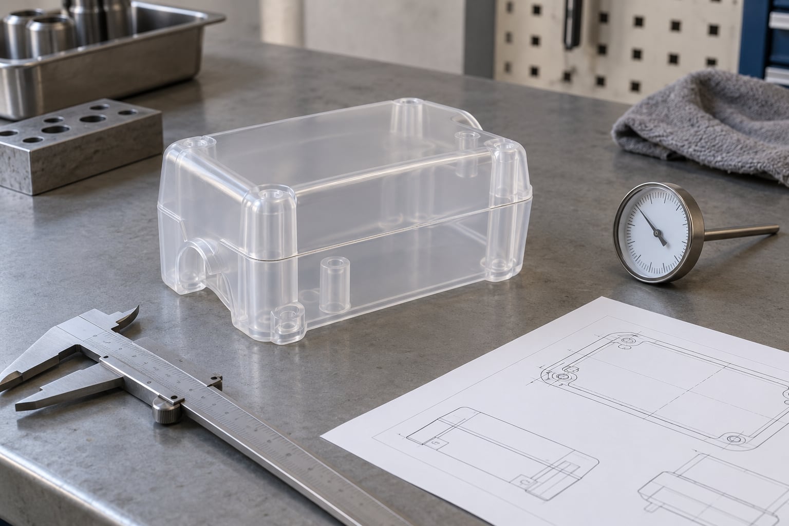
Weld lines in injection molding happen where two melt flow fronts, split by a hole, insert, boss or change in wall thickness, meet again and cool before they can fully fuse. Most are process problems you can fix by raising temperatures, speeding up the fill and venting the last point to fill. A smaller share are geometry problems that need a gate or CAD change. This guide walks through both, in the order a technician should work them.
None of this requires a production shutdown. Most weld line improvements come from a controlled trial on a scrap of the same lot, with one variable changed at a time.
Table of Contents
- What You Need Before You Fix Weld Lines in Injection Molding
- Step-by-Step: Diagnose and Fix Weld Lines in Injection Molding
- 1. Confirm the Defect and Map Its Location
- 2. Check Mold Temperature and Material Conditions
- 3. Review Injection Speed, Pressure, and Hold Settings
- 4. Evaluate Gate Placement: Where Weld Lines in Injection Molding Begin
- 5. Inspect Venting, Cooling, and Mold Condition
- 6. Validate the Fix with Production Data
- Common Mistakes
- Frequently Asked Questions
- Conclusion
What You Need Before You Fix Weld Lines in Injection Molding
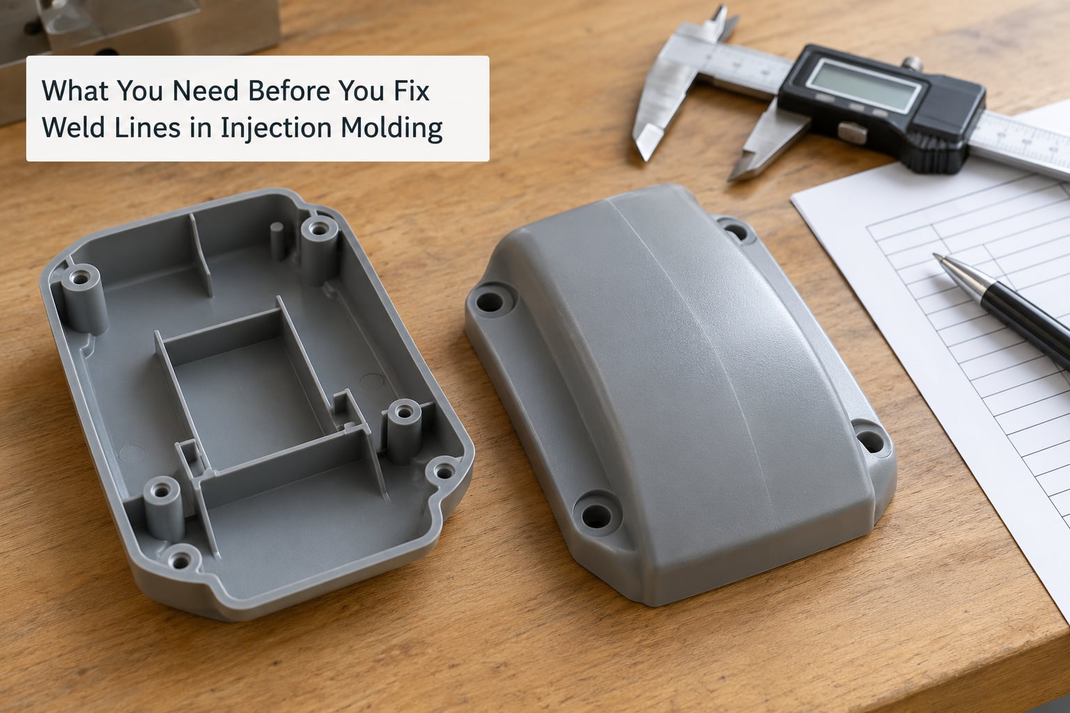
A weld line, also called a knit line, is the seam left where two or more advancing melt fronts converge and the polymer chains at the interface never fully interdiffuse. Because the seam did not fuse completely, it is the weakest section of the part and it is usually visible as a faint line, notch or gloss shift.
Before touching a process setting, gather four things. You need a known-good comparison part or setup sheet from when the seam was not there. You need the resin data sheet, with the melt temperature range and the drying requirement for the specific grade. You need the current setup: melt and mold temperature, fill time, hold pressure and time, screw speed and back pressure. And you need a way to judge the result, which means a dimension gauge, a light box or inspection lamp, and for structural parts, a coupon or a test fixture.
Weld lines matter for four separate reasons, and which one you are dealing with decides the whole approach.
- Strength. The seam is a weak plane. Tensile and impact losses of up to roughly 30 percent are reported in unfilled thermoplastics, and glass-filled grades are usually worse because the fibres align along each flow front instead of bridging across it.
- Appearance. On high-gloss, textured or painted faces a single seam can reject an entire batch, because paint coverage changes across a non-fused surface.
- Sealing. A knit line crossing a fluid path is a leak path. Pressure-tight housings and medical fluid components are usually designed so the seam never crosses the seal.
- Stress and compliance. Moulded-in stress concentrates at the seam. On a part that flexes in service, the failure usually starts there rather than in the bulk material.
Two practical checks before you start. Photograph the same cavity on five consecutive shots. If the line sits in the same place every time, you are looking at geometry. If it wanders, you are looking at hesitation or race tracking, which is a fill-pattern problem, not a mold defect. Also decide now whether the seam is cosmetic or functional, because that decision determines whether you chase elimination or a documented acceptance limit.
Step-by-Step: Diagnose and Fix Weld Lines in Injection Molding
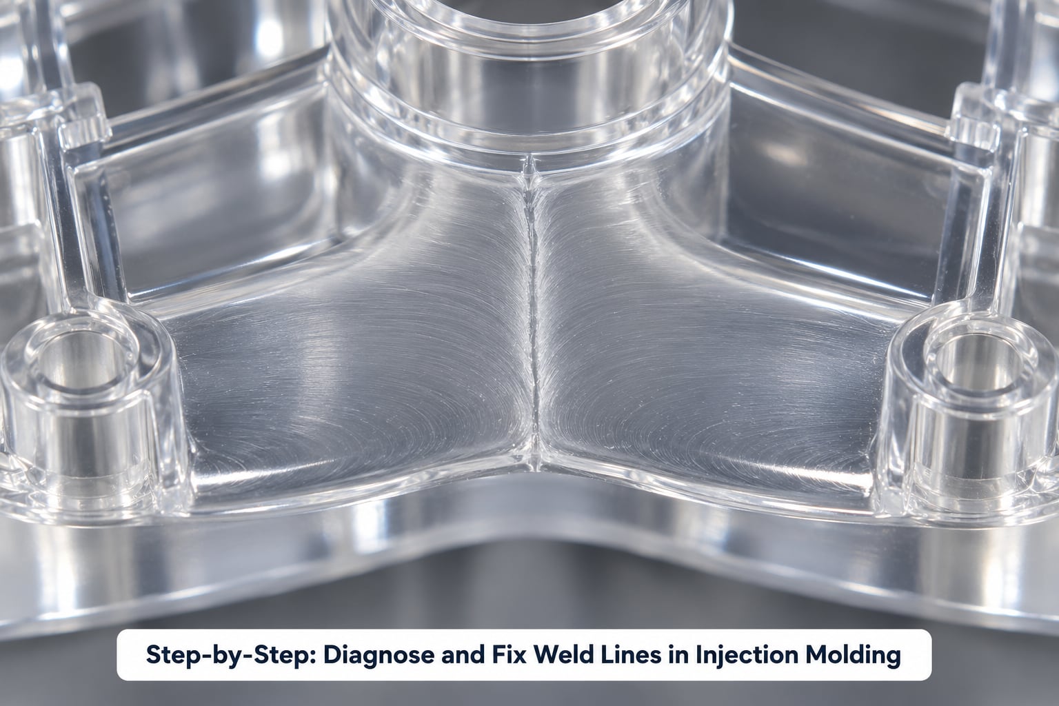
Work the process before you touch the CAD, and the cheap settings before the expensive ones. Every step below ends with a check that tells you whether to keep going or move on.
1. Confirm the Defect and Map Its Location
Confirm the defect first, because knit lines are frequently mistaken for flow marks, jetting, flash or sink. A weld line runs across the part from one obstacle toward the far side, directly downstream of whatever split the flow. A flow mark follows the direction of travel and looks like a faint orange-peel streak. Jetting is a single thick worm of material starting at the gate. Flash is excess material past the parting line. Sink is a dimple on a thick section.
Mark the line on the drawing with its distance from the gate. That distance tells you the flow length at the moment of meeting, and it is the single most useful piece of information you can carry into the rest of the process.
Then check whether it is the same in every cavity. A seam that appears in one cavity of a multi-cavity tool usually points at runner balance rather than at the part.
| What you see | Likely driver | First lever to try |
|---|---|---|
| Faint seam, stationary, low-melt gloss shift | Cold flow fronts, slow fill | Raise melt temperature 10 to 15 C within the resin range |
| Seam plus silver streak or burn mark at the line | Trapped air compressed at the junction | Add or clear vents at the last point to fill |
| Seam that wanders between shots | Hesitation, race tracking, inconsistent melt temperature | Fill the cavity in a controlled multi-stage profile |
| Line that moves when the gate is moved | Two or more gates converging late | Use a single dominant gate or rebalance the runner |
| Seam at a hole, insert or boss, always in one place | Geometry-driven flow split | Redesign the obstacle or move the gate to shift the seam |
| Seam that weakens the part under load | Low weld strength in this resin family | Change resin or change the load path, not the pressure |
Success check: the seam is on the drawing, its cause category is identified, and you have one known-good part to compare against.
2. Check Mold Temperature and Material Conditions
A weld line forms when the two fronts are too cold to interdiffuse, so temperature is the first lever and the cheapest one. Raise the mold temperature by 20 to 30 C, and the melt temperature by 10 to 15 C, staying inside the supplier’s window. Hold mold temperature control within about 1 C, because a swinging mold face gives you a seam that comes and goes with the cycle.
Amorphous resins such as ABS and polycarbonate respond well to heat, since they hold a wide processing window. Crystalline grades such as nylon and POM are narrower, and pushing them too far invites short shots and flash instead of a better weld.
Check the material side with the same attention. Verify the dryer dew point is at or below minus 40 C for hygroscopic grades, confirm the residence time in the dryer is long enough for the shot size, and log the resin lot. Wet resin gives you splay and a dull seam, and in hydrolysis-sensitive grades it also costs you molecular weight, which shows up as a brittle seam that never seems to heal no matter how hot you run it.
Regrind rate is the other half of this step. Rising regrind raises viscosity and lowers weld strength, so compare a 100 percent virgin shot against production mix before you blame the mold.
Success check: the seam visibly narrows or disappears on a scrap run, and the part shows no new flash, short shot or dimensional drift.
3. Review Injection Speed, Pressure, and Hold Settings
If heat did not close the seam, the fronts are probably arriving too late in the fill. Increase the fill rate, or switch to a multi-stage injection profile: a slower stage to fill the gate and runner, a fast stage to fill the cavity, and a controlled reduction near the end of fill so the last-to-fill region gets pressure without turbulence.
Aim for a fill time that suits the part and the machine. Slow, single-stage fills give the fronts time to cool before they meet, and they invite hesitation. Very fast fills do the opposite: they shear the melt, push air into the seam and can turn a knit line into a visible burn mark.
Be clear about what hold pressure can and cannot do. Hold and pack pressure control shrinkage after the gate seals. Once the gate has frozen, raising pack pressure has no effect on a weld line that formed during fill, which is a common and expensive misunderstanding on the shop floor. If the seam is present at end of fill, more pressure will not heal it.
Screw speed and back pressure do influence the weld indirectly. Plasticising that is too aggressive breaks long chains and traps volatiles into the melt, so if the seam is dull rather than crisp, reduce back pressure first.
Success check: cavity pressure and fill time are repeatable, and the seam position is fixed from shot to shot.
4. Evaluate Gate Placement: Where Weld Lines in Injection Molding Begin
Gate placement decides where your flow splits, and that is why moldmakers insist on reviewing knit lines before the steel is cut. A single dominant gate, placed so melt reaches the far end of the part on one continuous front, leaves you with no seam at all. Multiple gates force two fronts to converge, and the seam appears wherever they meet.
Long flow lengths make this worse, because the first front has cooled and lost pressure by the time the second arrives. Adding a second gate to shorten fill time can quietly double your weld lines, which is a trade worth understanding before anyone makes it. If you are chasing a short shot, our short shot troubleshooting guide for molders covers the fill side of that balance.
Review the ten gate placement mistakes to avoid in injection molding before a redesign. The common ones show up as a seam directly opposite a hole, a boss placed where the flow has already split, and a gate sized so small that the melt freezes before it reaches the split.
Gate type matters too. A fan or film gate spreads flow across a wide wall and usually creates fewer seams than a submarine or pin gate on the same part, at the cost of a visible gate mark and more difficult ejection.
When you must move the seam rather than remove it, aim for a rib, an internal wall, a thick section or a non-cosmetic face. A seam buried in a fillet or hidden under a boss is a solved problem.
Success check: you can point to the flow split on the drawing and state, in one sentence, why the two fronts meet where they do.
5. Inspect Venting, Cooling, and Mold Condition
Air trapped at the convergence point gets compressed between the two fronts, and that is what turns a faint seam into a silver streak or a burnt mark. Vents go at the last point to fill and at dead corners. A typical vent is 0.02 to 0.05 mm deep and 3 to 6 mm wide, deepening beyond that range at the wear land near the parting line where vent wear happens first.
Blocked or undersized vents are common on older tools. Our guide to venting problems in injection molds covers how to spot a vent that has been painted shut by release agent, and why a vent at the wrong end of the cavity does nothing for you.
Now look at cooling. Uneven cooling across the seam means one front is colder than the other, and conformal cooling channels or a rebalanced circuit buy more than another 10 C of mold temperature. Check alignment, parting-line wear and any flash or damage around the hole or insert, since a deformed core pin changes the flow split from one shot to the next.
Excess release agent deserves its own check, since it is a genuine cause and usually an easy one. A silicone film on the surface blocks chain interdiffusion at the seam and dulls gloss. Wipe the cavity and run ten clean shots before you conclude the material is the problem.
Success check: clean vents, no release agent film, and a mold temperature you can hold to about 1 C through a full cycle.
6. Validate the Fix with Production Data
Validate on a controlled run, not on impressions. Run a short shot study to find the short-shot limit, then confirm the weld line at a fill you can actually hold with margin. Log cavity pressure or fill time across the run so you have a trend instead of a snapshot.
Inspect first articles against a fixed standard: dimensions across the seam, the seam itself under consistent lighting, and any surface the customer sees. For structural parts, cut coupons that cross the weld line and run a bend or tensile test, then compare against a sample with no seam. If the part is pressure-tight, run the seal test with the seam deliberately placed in the flow path.
Set the acceptance criteria in writing while you are at the machine, not after a customer complains. Our short shot troubleshooting guide uses the same discipline: a documented limit beats an argument on the floor.
Document which change fixed it on the setup sheet, then verify it survives a resin lot change and a mold temperature check. A setting that only worked once is not a fix.
Success check: the seam meets your written cosmetic or structural criterion across a full run, and the setup sheet records the change.
Common Mistakes
Changing four settings at once. You will get a better part and learn nothing. Correct it by changing one variable per trial, labelling every sample and keeping the ones you measured.
Raising hold pressure to fix a fill-time seam. Pack pressure acts after the gate freezes and cannot re-fuse a seam that formed during fill. Correct it by going back to fill rate, melt temperature and venting.
Moving the gate without a flow analysis. A new gate fixes one seam and creates another downstream. Correct it by running mold flow simulation first, or at minimum by drawing the split and merge on the print.
Treating every weld line as a reject. A seam on an internal rib is normal and accepted in almost every program. Correct it by writing a cosmetic or structural criterion and letting the shop run to it.
Assuming the resin is the answer. Some materials have genuinely poor weld strength, especially glass-filled grades and highly filled compounds. Correct it by testing weld strength on the specific grade before committing to a process tune that will never reach target.
Ignoring the seam when the tool is designed. A weld line crossing a seal or a load path should be settled at gate-layout review. Correct it by running a DFM check before steel is cut, not after the first field failure.
Frequently Asked Questions
Do weld lines always weaken the part?
Not always, but the seam is usually the weakest section of the part. Unfilled thermoplastics can lose up to roughly 30 percent of tensile strength across the line, and glass-filled grades lose more because fibres align along each flow front instead of bridging the join. On a part that does not flex or seal near the seam, a fused weld line is usually acceptable. Test the specific grade and the specific loading before you decide.
Can weld lines be completely eliminated?
Sometimes, yes. A single dominant gate that sends one continuous melt front from the gate to the far end of the part can leave no seam at all. Any part with a hole, a boss, a thickness change or two gates has a flow split somewhere, and a seam is geometrically unavoidable there. In those cases the realistic goal is a strong, stable, well-vented seam placed in an area that does not carry load or show.
Should I fix weld lines with higher pack pressure?
No. Pack and hold pressure control shrinkage after the gate seals, so raising them does nothing for a seam that formed during fill. Use the fill window instead: raise melt temperature 10 to 15 C, raise mold temperature 20 to 30 C, increase fill rate or use a multi-stage profile, and clear the vents at the last point to fill.
How do I know if my mold has adequate venting?
Look for the two classic signs. A silver streak or burn mark right at the seam means air is being compressed between the converging fronts, which points at venting or speed. Vents should sit at the last point to fill and at dead corners, typically 0.02 to 0.05 mm deep by 3 to 6 mm wide, with the wear land on the parting line opening up first as the tool ages.
How do I test weld line strength?
Cut coupons that cross the seam and run a bend or tensile test on them, then compare against coupons from a region with no seam on the same part. For fluid-handling parts, add a pressure or leak test with the seam in the flow path. For appearance, set a written limit under fixed lighting rather than relying on a verbal pass.
Why do weld lines show up in glass-filled nylon housings?
Glass fibres orient along the direction of flow, so each of the two fronts arrives with its own fibre alignment. The fibres do not bridge across the interface, and they also stiffen the melt so it cools and stops flowing sooner. Higher mold temperature, a faster fill and correct drying help, but glass-filled housings usually need the seam moved to a rib or internal wall as well.
Conclusion
Start by confirming where the seam is and how far it sits from the gate. Compare that shot against a known-good condition, then change one variable at a time: temperature first, then fill rate, then venting, then material, and gate design last. Document each result on the setup sheet so the next shift inherits an answer instead of a rumour. Updated for 2026, and still the same rule as ever: a weld line you understand is a problem you can close, and one you ignore shows up in the field.