
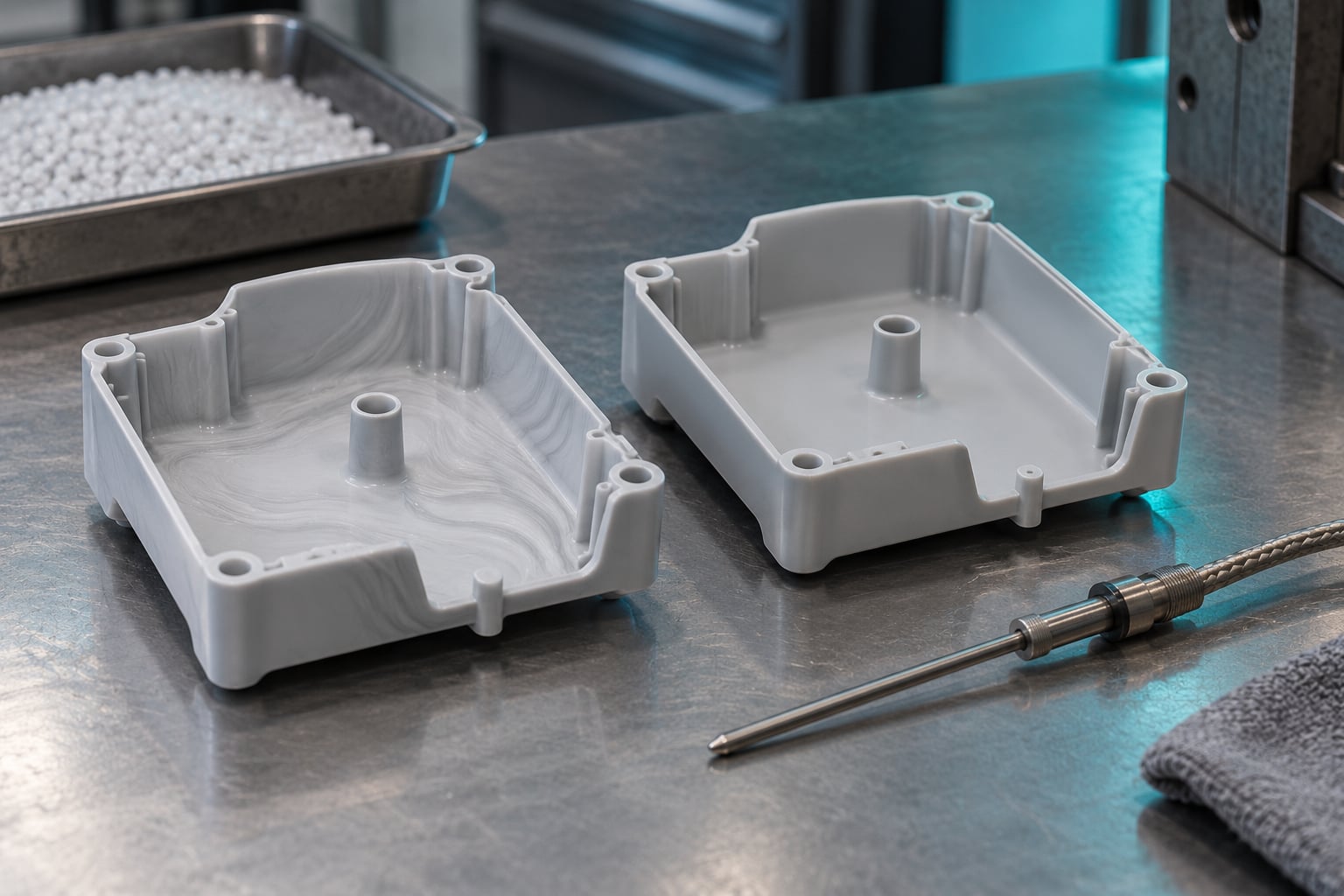
Flow lines in injection molding form where the melt front hesitates, stalls or freezes against a cold cavity wall before hotter resin pushes past it and leaves a permanent scar. To remove them, correct the fill in this order: confirm the defect is really a flow line, rule out degraded or wet resin, raise melt temperature and injection speed, then move to mold temperature, gate geometry, venting and surface finish. Change one variable per trial.
The order matters because each step costs more than the last. A temperature adjustment takes a minute and a scrap bin of a few shots. A gate change takes weeks of steel work and a new first-article approval. Most shops that try to skip ahead end up polishing a symptom and coming back to the same complaint three lots later.
What follows is the sequence I would walk a new process technician through on their first flow-line call, plus the finishing options that work when the part is already out of the machine.
Table of Contents
- What You Need Before You Start Troubleshooting Flow Lines
- Step-by-Step: How to Remove Flow Lines in Injection Molding
- 1. Diagnose Whether the Marks Are Flow Lines
- 2. Document the Resin and Material Condition
- 3. Review Melt Temperature and Material Flow
- 4. Inspect the Gate and Fill Pattern
- 5. Check Mold Temperature and Cooling
- 6. Correct Packing, Hold Pressure, and Venting
- 7. Refine the Surface-Finish Process
- 8. Verify the Correction With Controlled Trials
- Common Mistakes When Troubleshooting Flow Lines
- Frequently Asked Questions
- Are flow lines in injection molded parts a strength problem?
- Can polishing remove flow lines without changing the molding process?
- How do I tell the difference between a flow line and a weld line?
- When should I change the gate or cavity design to correct flow lines?
- Do flow lines always indicate an incorrect mold temperature?
- How do I verify that a flow-line correction did not create new defects?
- Conclusion: Start With One Controlled Trial, Not a Mold Order
What You Need Before You Start Troubleshooting Flow Lines
You need the current process sheet, the resin drying record, the mold history and a way to judge the defect consistently. Without those four things you are guessing, and guessing is what turns a ten-minute fix into a week.
- Process data: barrel zone setpoints, actual melt temperature if the machine logs it, mold temperature setpoints and the readings at each cavity, injection speed profile, fill and hold pressures, hold time, back pressure, screw speed and the V/P transfer position.
- Resin records: grade, lot, supplier processing window, moisture reading or dew point from the dryer, hours of residence time in the barrel, regrind percentage, pigment or masterbatch loading, and the last drying cycle with its temperature and hold.
- Tool information: gate size and type, gate angle, gate position relative to the mark, runner layout, number of cavities, and any recent mold work. If the mold was reworked or replated, that usually changes the picture.
- Venting status: when the vents were last inspected, whether any vent is furred with plastic or flashed over, and whether the ejector pins are acting as vents because of wear.
- Cycle history: the current stable cycle data plus whatever settings were running when the marks started appearing. A defect that arrived with a material change is a material problem until proven otherwise.
- Inspection method: a consistent light source, the texture specification for comparison, and a defined acceptance rule for cosmetic surfaces. Our venting problems explained guide covers how blocked vents show up as surface marks.
Have trial material ready and a scrap plan in mind. You should be able to shoot a short run of thirty to fifty parts without releasing them to production.
Step-by-Step: How to Remove Flow Lines in Injection Molding
1. Diagnose Whether the Marks Are Flow Lines
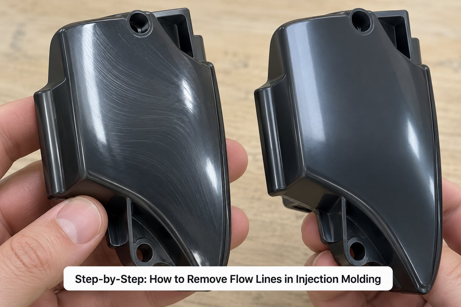
Confirm the defect type before you touch a machine setting. Flow lines follow the direction the melt traveled, repeat at the same place every shot, and sit shallow in the surface with a gloss or color difference rather than a physical step.
Weld lines are where two melt fronts met and the material fused imperfectly. They usually sit where material splits around a hole, insert or core pin and travel outward from that point. Jetting is an uncontrolled stream that hits the far cavity wall and makes a sausage-shaped ridge. Splay, or silver streaks, follows a shear path and looks like short silvery lines near the gate or the thickest section. Scratches and polishing marks show up under raking light but do not move when the fill pattern changes.
If the marks sit behind the gate, run in several directions, and only appear in one cavity, you are probably looking at a cold or blocked cavity rather than a process window problem. If they show in every cavity at the same wall location, suspect the process first.
2. Document the Resin and Material Condition
Flow lines form when the melt is too weak or too viscous to keep the leading edge moving. Confirm the resin is not the reason before adjusting anything.
Pull a moisture reading on hygroscopic materials like polycarbonate, nylon and PET. Wet resin produces splay and silver streaks, and the reduced viscosity makes the melt front fragile. Excessive regrind shortens polymer chains and cuts melt strength, which shows up directly as hesitation. Check the ratio on the hopper and whether regrind from a different grade or color is mixed in. A heavy masterbatch loading does the same thing by raising viscosity and dulling gloss.
If the dryer has been running without a purge, or the material sat in a hopper overnight, say so in the trial record. Fix the material condition first and re-evaluate before moving on. A lot change or a resin swap that coincided with the marks is a strong enough signal to test material before process.
3. Review Melt Temperature and Material Flow
Compare the current barrel settings with the resin supplier’s processing range, then raise temperature in small steps rather than one large jump. The goal is to give the melt front enough fluidity and heat to stay ahead of the freezing skin.
Distinguish setpoint from actual melt temperature. A barrel zone setpoint is not the melt temperature at the nozzle; it varies with screw design, shear rate, barrel length and how long the material has been in the barrel. If your machine logs a melt thermocouple, use it. If it does not, measure with an air-shot pyrometer before assuming the barrel reading is accurate.
Test in increments of 5 to 10 degrees C, holding each new setpoint for a full cycle or two and inspecting the same critical zone before deciding. Going too high costs you cycle time through longer cooling, can degrade the resin, and can push gloss variation into a different range.
| Resin | Melt temperature starting point | Mold temperature starting point | Notes on flow lines |
|---|---|---|---|
| ABS | 220-250 C | 50-70 C | Widest processing window of the common resins; temperature changes show up quickly |
| PP | 200-230 C | 30-60 C | Crystalline, so skin forms fast; mold temperature matters more than melt temperature |
| PC | 280-300 C | 80-120 C | Needs hot molds and dry resin; low melt strength makes hesitation marks obvious |
| PC/ABS | 260-290 C | 70-100 C | Blend viscosity sits between the two parent resins |
| PMMA | 220-260 C | 60-90 C | Very visible on clear parts because the melt stays clear and gloss contrast is high |
| POM | 190-220 C | 60-90 C | Low melt strength and fast set; keep residence time short |
These are starting points for a trial, not a substitute for the supplier’s data sheet. If a change in injection speed shifts the marks more than a temperature change does, speed is your dominant variable and you should move to step four with that in mind.
4. Inspect the Gate and Fill Pattern
Flow lines originating at the gate are a geometry problem more often than a temperature problem. A small gate behaves like a nozzle and beats up the material, which leaves surface streaks radiating from it.
Measure the fill pattern on a short shot: mold a few parts at low fill and look at where the front stopped and what shape it had. Check the flow length against the wall thickness ratio in the thin sections. Long fills through thin walls give the front time to freeze before the last section fills.
Look for abrupt thin-to-thick transitions, which force the front to accelerate and slow again, and for competing fronts that split around a feature and rejoin. Gate angle matters too. A shallow angle produces a jet that strikes the wall before it has spread. Angles in the range of 40 to 50 degrees let the cavity wall break up the stream naturally.
Some of this responds to process work: a slower first-stage fill can reduce the shear that marks the gate area, and a balanced runner can stop one cavity filling ahead of another. Gate size, gate position, gate type and runner balance do not. Those need mold work, and no setting change will substitute for them.
5. Check Mold Temperature and Cooling
Cold tool steel is the single most common trigger practitioners report. A cold cavity wall pulls heat out of the leading edge of the melt, and a thin frozen skin forms before the part fills. The hotter resin behind it then pushes past that skin and leaves the line.
Measure the mold temperature at the cavity wall where the marks appear, not just at the water inlet and outlet. Averages hide imbalance, and the feed block can read warm while one cavity runs cold because of a fouled or partially blocked circuit. If the marks appear in one cavity only, compare its cooling in more detail.
Test by raising mold temperature in steps and watching for the side effects: longer cycle time as cooling slows, dimensional shift as the part comes out hotter, and in high-temperature tools, condensation on the cavity surface. Water on a cold cavity creates its own silver marks and can easily be mistaken for a resin problem.
Blocked or fouled circuits are a maintenance item, not a setting item. Our mold maintenance schedule for injection molding lays out the cooling checks that fit into a planned shutdown rather than a production emergency.
6. Correct Packing, Hold Pressure, and Venting
Trapped air shows up as marks near the end of fill, where the last to close region holds gas behind a frozen front. Inspect vent condition before adjusting pressure. A vent furred with plastic or flashed over stops venting, and the classic sign is a mark that stays in the same spot regardless of temperature changes.
Check the V/P transfer position against the fill time. If the machine switches from velocity to pressure early, the front fills slowly and hesitation has more time to happen. Moving transfer closer to full fill often helps, within the machine’s approved limits and the material’s shear guidance.
Hold pressure and hold time affect sink and void control more than surface appearance. Increasing them heavily to chase a cosmetic mark raises the risk of flash, parting line mismatch and dimensional drift, so treat hold pressure as a controlled variable rather than a lever. Confirm any change with quality before releasing parts, because a visually better part that no longer meets the drawing is a reject in a different column.
7. Refine the Surface-Finish Process
Surface finishing handles what the process cannot. It works well on shallow marks on small, low-volume cosmetic parts, and it works badly on textured surfaces where the mark crosses the texture peaks.
On glossy molded surfaces, operators have a well-worn physical route: warm the part with a heat gun to soften the skin slightly, scrape or carefully sand the ridge level with a fine blade or abrasive, step the grit down through medium to fine sandpaper, finish with polishing compound and buff with a clean cloth. On clear parts, vapor or flame polishing is another option, and it works best on flat surfaces away from the gate vestige.
Know the limits. Sanding leaves matte haze on a high-gloss surface that sometimes reads worse than the original line, and solvents craze ABS and stress-whiten PC if you go slowly on a thick section. Polishing also removes material, so it changes dimensions on a tight-tolerance face and cannot reach a mark in a recess a tool will not enter.
Also rule out the non-flow-line explanations before finishing. Polishing does nothing for flash, a scratch, a tooling texture that is deeper than the texture specification, or a part that was molded with a wrong material. A high-gloss surface with mold plating or a fine EDM texture needs a different corrective path than a matte part, and we would look at simulation before cutting steel.
8. Verify the Correction With Controlled Trials
Verify like you mean it: change one variable per trial, hold everything else, and compare against the same inspection standard every time.
Keep the previous cycle data in the trial record. When a later process change appears to fix something, you need to know what the settings were when it stopped. Photograph the critical zone under the same lighting, not under whatever light happens to be over the bench.
Sample enough shots to see the tail, not just the first good one. Take parts across the full run and from every cavity, because cavity-to-cavity differences tell you whether you fixed the process or just moved the window. Compare first articles against the drawing, the texture specification and the written cosmetic acceptance criteria.
Then check that you did not trade one defect for another. Flow lines down and flash up means you went too far on pressure or pack. Gloss even and cycle time up 20 percent is a real cost that quality will notice at the next cost review. Log the acceptance decision, the parameter set and the trial data so the next shift can repeat it, and fold the failure mode into an FMEA for injection molding processes when it has cost you more than one lot.
Common Mistakes When Troubleshooting Flow Lines
Almost every long investigation I have seen started with one of these seven errors.
- Raising temperature in one big jump. You lose the ability to see which step helped, and you pay for degradation and cycle time. Step it up in increments instead.
- Polishing before diagnosing the cause. A polished part proves nothing and destroys your evidence. Finish work is the last step, not the first.
- Changing several variables at once. Two changes that each help a little look like one big fix, and the process window shrinks until the next material lot breaks it. One variable, one trial, one conclusion.
- Calling every line a flow line. Weld lines, jetting and splay need different fixes. Misrouting the diagnosis wastes a week.
- Overpacking to close a surface gap. Hold pressure and hold time do not cure hesitation, and raising them brings flash and parting line problems with them.
- Accepting a visually better part that fails dimension. Improvement in appearance with drift in wall thickness or flatness is a regression, not a fix. Check the drawing before you call it solved.
- Treating a mold change as a settings change. Gate size, gate position and runner balance live in steel. If process work has plateaued, stop cycling settings and get a mold review.
The rule underneath all seven is simple: change one thing, write down what you changed, and keep the part if it improved.
Frequently Asked Questions
Are flow lines in injection molded parts a strength problem?
Usually no. Flow lines form at the surface where the melt front hesitated, and the frozen skin they leave is thin compared with the wall. They are a cosmetic defect in most designs. The exception is a flow line that coincides with a weld line or a notch in a highly stressed area, where you are looking at a stress concentrator rather than a cosmetic mark. If the part carries a load, cut a section through the mark and check it rather than judging by eye.
Can polishing remove flow lines without changing the molding process?
Sometimes, and only on specific parts. Shallow marks on small, low-volume cosmetic parts can be sanded and polished level, and clear flat parts can be vapor polished. It rarely works on textured surfaces where the mark crosses the texture peaks, it changes dimensions on a tight-tolerance face, and it leaves matte haze on a high-gloss surface. Polishing also hides the root cause, so the next lot usually repeats the defect.
How do I tell the difference between a flow line and a weld line?
A flow line runs along the direction the melt traveled and repeats at the same location on every shot, usually just behind the gate or around a thin section. A weld line forms where two separate melt fronts met and fused imperfectly, so it starts at a split point such as a hole, insert or core pin and radiates outward from it. Cut a section through the mark: if it is a shallow surface scar you have a flow line, if the interior shows a fused seam you have a weld line.
When should I change the gate or cavity design to correct flow lines?
Change the gate or cavity design when process settings have plateaued and the marks still originate at the gate or at a fixed wall location. Small gate size, a shallow gate angle, a distant gate, poor runner balance and abrupt thin-to-thick transitions are geometry problems and no setting corrects them. Before cutting steel, run moldflow analysis to confirm the fill pattern and check the flow length against wall thickness ratio in the thin sections.
Do flow lines always indicate an incorrect mold temperature?
No, mold temperature is only one of several causes. Cold tool steel is the most common trigger, but low melt temperature, a cold resin, excessive regrind, a small or shallow gate, a long flow length through a thin wall and trapped air behind a frozen front all produce the same visible mark. Raise the mold temperature in controlled steps and see whether the mark responds. If it does not move, you are chasing the wrong variable.
How do I verify that a flow-line correction did not create new defects?
Sample across a full short run rather than the first good shot, and take parts from every cavity. Photograph the same critical zone under the same lighting, then check the part against the drawing and the cosmetic acceptance criteria for flash, parting line mismatch, warpage and gloss variation. Also compare cycle time against the previous process data, because a hotter mold or a slower fill fixes appearance and quietly adds seconds per shot.
Conclusion: Start With One Controlled Trial, Not a Mold Order
Flow lines in injection molding come from a melt front that stopped moving, so the fix depends on why it stopped. Confirm the defect is a flow line and not a weld line, jetting or splay, document the resin condition and the current cycle data, then run one controlled trial on melt temperature or injection speed and judge it under consistent light. If the mark will not move after process work has plateaued, the problem is in the gate, the fill pattern or the venting, and that is a mold conversation. Save the polishing compound for parts you have already decided to keep.