
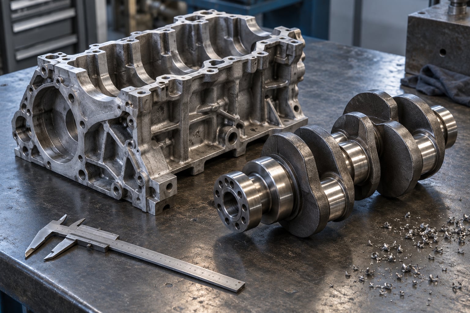
Last updated October 2026. This guide covers the differences buyers, engineers and quality teams run into most: strength, geometry, tolerances, tooling cost, defect risk and the volume at which each process starts to make sense.
Casting forms metal by pouring molten liquid into a mold and letting it solidify. Forging shapes solid metal, already heated to a workable temperature, by applying compression with hammers or presses. Because forging deforms and refines the grain structure of solid metal, forged parts generally carry higher tensile strength, ductility and fatigue life, while castings tolerate complex shapes, very large sections and alloys that cannot be worked hot.
That is the short version. The useful version is narrower: neither process wins everywhere. Forging usually takes fatigue-critical, tensile-loaded parts such as crankshafts, connecting rods and pressure fittings. Casting usually takes complex housings, manifolds, pump bodies and large structural sections, and it often does the job cheaper at volume.
One correction before we go further, because it comes up constantly in buyer conversations. Forging does not compress metal or squeeze out voids to reduce volume. It breaks up coarse dendritic grains into a finer, more uniform structure and closes some porosity, and that refined structure is what raises fatigue strength. Volume essentially does not change, and a forged part is often heavier than the casting it replaced.
Table of Contents
- Casting vs Forging Differences at a Glance
- How Casting and Forging Shape Metal Differently
- How Materials and Mechanical Properties Compare
- Strength, Ductility, and Defect Risks
- Dimensional Accuracy, Surface Finish, and Geometry
- Tooling, Lead Time, Cost, and Production Volume
- Quality Control and Inspection Requirements
- Where Cast and Forged Parts Win
- Which Should You Choose?
- Frequently Asked Questions
- Conclusion
Casting vs Forging Differences at a Glance
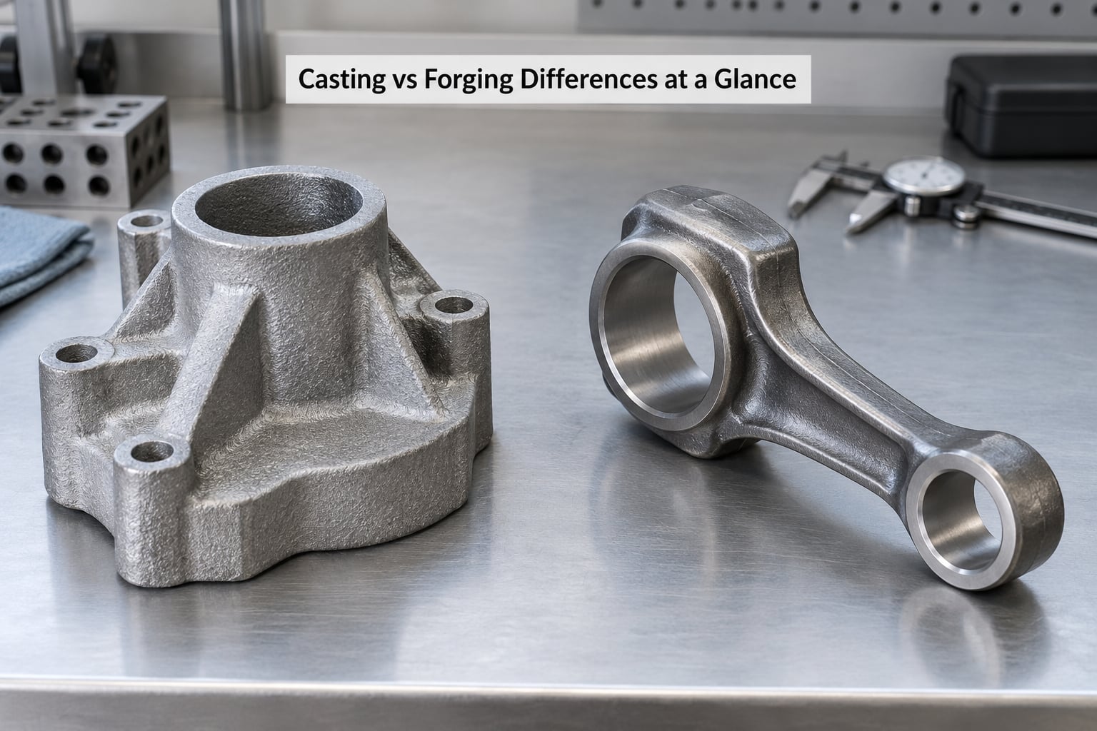
The table below is the condensed version of everything that follows. Values are typical for commercial production, not specification minimums, and cast-versus-forged strength figures depend heavily on grade, section size and heat treatment.
| Criterion | Casting | Forging |
|---|---|---|
| Start state of the metal | Molten liquid | Solid, heated above recrystallization |
| Primary forming action | Flow into a cavity, then solidification | Plastic deformation under pressure |
| Tooling | Pattern, core box, and mold or die | Die set, or open-die tools |
| Grain structure | Coarse dendritic, generally isotropic | Fine, worked, usually anisotropic |
| Tensile strength (same alloy) | Lower, typically 20 to 40 percent below wrought | Higher; the reference for fatigue design |
| Ductility and impact toughness | Lower, more notch sensitive | Higher, better impact absorption |
| Compressive and multi-axial strength | Very good, and often the deciding factor | Good, but grain-flow sensitive |
| Fatigue life | Limited by surface porosity and inclusions | Substantially longer in rotating or cyclic service |
| Achievable tolerance (as cast/forged) | About 0.125 inch on critical features, better after machining | About 0.06 to 0.10 inch, better on impression dies |
| Surface finish | Sand-cast skin to smooth die-cast skin | Die-scaled skin, often showing metal flow lines |
| Draft required | Roughly 1 to 1.5 degrees on sand-cast walls | More, often several times the casting draft on deep features |
| Internal geometry | Cores make deep blind pockets and curved passages | Undercuts are difficult; no free internal cavities |
| Section thickness | Wide range, heavy sections up to many inches | Ratio of thickness to width is limited by flow |
| Size limit | Very large single parts are practical | Large parts need multiple operations and large presses |
| Tooling cost and lead time | Lower for one-off and low volume; patterns are quick | Higher; die development and tryouts dominate |
| Break-even behaviour | Pattern cost amortizes quickly, unit cost falls with volume | Die cost amortizes quickly, unit cost falls with volume |
| Typical defect set | Porosity, shrinkage cavity, hot tear, sand inclusion, cold shut | Laps, seams, bursts, cold shuts, tears, coarse grain |
| Weldability | Generally easier, lower preheat on many grades | Good on many grades, but higher hardenability to plan for |
| Machining needs | More allowance, but less for complex internal shapes | Less allowance; tool life is more predictable |
| Typical uses | Pump and valve bodies, manifolds, engine blocks, large frames | Crankshafts, gears, fasteners, connecting rods, high-pressure flanges |
Two rows in that table are worth pausing on. Compressive and multi-axial strength is the row most people skim, and it is often the row that decides the answer: a casting under pure compression can outperform a forging because a forging’s extra material usually sits in tension-loaded flow lines. And isotropic versus anisotropic is the distinction most summaries get wrong.
How Casting and Forging Shape Metal Differently
Casting starts with a pattern, a reusable replica of the part, which makes a cavity in sand, plaster, shell or a permanent metal mold. Cores create the internal passages. Metal is melted, poured or injected, fills the cavity, and solidifies in place before the part is shaken out, gated, risered, heat treated and finish machined.
Forging starts with solid stock, an ingot or a continuously cast billet. The stock is heated, then pressed or hammered in a die, often through several operations with reheats in between. The part comes off the press with flash and a parting line, gets trimmed, normalized or quenched and tempered, and then machined.
Both routes finish the same way in one respect: material only ends up where the design puts it. Neither process adds material to make a part bigger than the cavity or the die cavity it formed in, so designers use ribs, lugs and cored passages to move strength around rather than thickening walls uniformly.
If you are working on polymer tooling rather than metal, the same pour-versus-press logic shows up in a different form. Our guide to when to use urethane casting instead of molding covers that side, and the comparison between blown film and cast film differences uses the same cast-versus-oriented framing in a completely different material.
Casting vs Forging Differences in Production
Here is the two sequences side by side, using a ten-inch valve body as the reference part, because it is the classic case where the process split actually gets argued over in a purchasing meeting.
Casting route: pattern and core boxes are made, the mold is packed and hardened, the melt is poured and allowed to freeze, the casting is knocked out of the sand, gates and risers are cut off, the part is heat treated, then inspected and machined. Solidification is the whole story. Metal cools from the outer wall inward, dendrites grow, and the last liquid to freeze is isolated in the heavy sections, which is where shrinkage porosity ends up.
Forging route: the billet is cut, a piece is cut from it, it is heated to forging temperature, and it is upset and pierced in the first die. It is reheated, rolled or stretched in a second die, reworked in a third if the shape needs it, then trimmed, heat treated and machined. Solidification already happened weeks earlier at the mill, so the forge is working with a fine, refined structure the whole time.
The grain structures you end up with are different in kind, not just degree. A casting solidifies with a coarse dendritic structure that is generally isotropic, meaning properties are close to the same in every direction. A forging, especially a closed-die or impression-die forging, develops a fiber or flow-line texture that follows the part’s shape, which makes it anisotropic: strong along the flow, weaker across it.
That anisotropy is the design’s best friend and its worst hazard. It is exactly why forgings survive crankshaft and connecting-rod service, where the material was deliberately routed to follow the load path. It is also why a forging fails in odd places when an engineer cuts across the flow with a bolt hole or a keyway.
How Materials and Mechanical Properties Compare
Forging and casting can use the same chemistry, but the same chemistry does not produce the same properties. The table below shows typical values from commercial part specifications, with the cast column representing well-run, heat-treated castings and the wrought column representing forged or otherwise plastically deformed material of a comparable grade.
| Material | Form | Yield strength (approx.) | Tensile strength (approx.) | Elongation | Hardness |
|---|---|---|---|---|---|
| 1020 carbon steel | Cast | 120 to 150 MPa | 200 to 230 MPa | 6 to 10 percent | 130 to 160 HB |
| 1020 carbon steel | Forged | 200 to 250 MPa | 380 to 430 MPa | 22 to 30 percent | 100 to 130 HB |
| 1045 carbon steel | Cast | 350 to 450 MPa | 570 to 630 MPa | 3 to 6 percent | 170 to 200 HB |
| 1045 carbon steel | Forged | 450 to 550 MPa | 630 to 730 MPa | 10 to 16 percent | 20 to 28 HRC |
| 4140 alloy steel | Forged and Q&T | 900 to 1,050 MPa | 1,100 to 1,250 MPa | 8 to 12 percent | 32 to 40 HRC |
| 4140 alloy steel | Cast | 700 to 800 MPa | 850 to 950 MPa | 2 to 4 percent | 28 to 34 HRC |
| 304 stainless | Cast (A351) | 170 to 210 MPa | 500 to 580 MPa | 6 to 10 percent | 150 to 180 HB |
| 304 stainless | Forged (A957) | 240 to 290 MPa | 585 to 690 MPa | 35 to 45 percent | 140 to 170 HB |
| 356-T6 aluminum | Cast | 150 to 170 MPa | 220 to 240 MPa | 2 to 4 percent | 75 to 85 HB |
| 6061-T6 aluminum | Forged | 255 to 280 MPa | 290 to 320 MPa | 10 to 14 percent | 95 to 110 HB |
| Gray iron, class 40 | Cast only | Not applicable | 100 to 150 MPa | less than 1 percent | 170 to 240 HB |
| Bronze, C95400 | Cast | Not applicable | 300 to 400 MPa | 5 to 12 percent | 150 to 200 HB |
Read the 1020 steel rows together and the pattern is clear: the forged version has roughly double the ductility and close to double the tensile strength of the cast version, in the same alloy. Aluminum shows the same behavior in miniature, with 6061-T6 forgings carrying about 30 percent more yield strength and four times the elongation of 356-T6 castings.
Now the other half of the alloy story, which no comparison table usually shows. Some materials are cast-only, and the reason is physics rather than preference.
Gray, ductile and white cast irons are cast-only in practice. Their carbon and silicon content leaves them with almost no ductility at forging temperatures, so a hammer or press simply cracks them instead of deforming them. High-carbon and high-sulfur or high-phosphorus steels behave the same way. Work-hardenable manganese steels, around 12 to 14 percent manganese, are another example: they have exceptional wear resistance but are produced as castings only, because they are impossible to work hot.
On the other side, a few alloys are only practical as forgings. Deep-drawing and HSLA grades, high-strength low-alloy steels and most wrought stainless conditions are specified in the deformed condition, because that is where their published properties come from. The Steel Founders’ Society of America makes the same point in a different direction: the codes do not hand forgings a mechanical advantage, because ASME B16.34 and the ASTM cast grades (A216, A217, A351) and forging grades (A957, A952) are written to comparable limits. The real difference is process capability, not the specification.
One genuine exception deserves a mention, because it gets left out of the standard arguments. Directional solidification, a controlled cooling technique used on premium castings, can orient a casting’s structure so that it outperforms a forging in a specific load case. Practitioners on machining and metallurgy forums have described exactly that result. It is expensive and narrow, but it is real, and it is the clearest evidence that the choice is application-specific rather than ideological.
Strength, Ductility, and Defect Risks
Forged parts provide more reliable fatigue strength; cast parts can offer complex geometry and better performance in compression, wear and multi-axial load. Both halves of that sentence matter, and the first half only holds if the forging was made with process control. Poor forging technique, wrong temperatures, insufficient reduction or skipped reheats can produce a part with a worse grain structure than a competent casting.
Ductility is the quieter advantage. Forged steel typically shows two to four times the elongation of a cast version of the same grade, and impact toughness scales with it. That matters when a part gets hit, dropped, shock-loaded or has to be repaired by welding, since a low-ductility casting has little margin before it cracks.
Defects are where the two processes differ most in kind. A casting’s problems come from solidification, and a forging’s come from surface condition and metal flow during deformation. The matrix below pairs each defect with its cause and with the inspection method that catches it.
| Defect | Process | Cause | Consequence | How it is found |
|---|---|---|---|---|
| Porosity | Casting | Gas entrained during pour, or insufficient feeding | Reduces fatigue life, causes leaks and blistering during machining | Radiography, ultrasonic testing, leak test |
| Shrinkage cavity | Casting | Isolated liquid metal in a hot spot, poor riser design | Severe local weakness, often in thick sections | Radiography, ultrasonic testing |
| Hot tear | Casting | Contraction restrained while the metal is still semi-solid | Crack open to the surface, can be a scrap condition at high severity | Visual, magnetic particle inspection |
| Sand or mold inclusion | Casting | Mold sand entrained in the pour | Tool wear, poor finish, stress raiser, coating defects | Visual, magnetic particle inspection |
| Cold shut | Casting | Two flows of metal meet without fusing | Unfused line in the casting, no strength at the joint | Visual, radiography |
| Lap | Forging | Scale folded into the surface during deformation | Surface crack that propagates under fatigue load | Visual, magnetic particle inspection, ultrasonic testing |
| Seam | Forging | Die mismatch or misalignment in the impression | Planar discontinuity along the die profile | Visual, magnetic particle inspection, ultrasonic testing |
| Burst | Forging | Excess material with no escape, or die too cold | Parting surface splits outward, part is scrapped | Visual |
| Cold shut or fold | Forging | Metal worked below proper temperature, poor lubrication | Unfused region, cracking during heat treatment | Visual, ultrasonic testing |
| Tear or crack | Forging | Excess reduction, uneven fiber flow, thermal stress | Crack running with or across the flow lines | Magnetic particle inspection, ultrasonic testing |
| Coarse grain | Forging | Insufficient reduction or excessive soak time | Reduced ductility and impact toughness despite high strength | Metallographic section, hardness traverse |
The practical consequence shows up on the shop floor more than in the design office. Machinists describe the frustration clearly: voids, inclusions and inconsistent density in castings break tools, wreck surface finish and cause plating or anodizing defects downstream, while forgings machine and finish predictably. A casting can be perfectly sound and still be the harder part to run on a line.
One myth worth retiring while we are here: a forged part is not automatically lighter than a casting of the same function. Steel castings are often lighter than their forged counterparts precisely because a foundry can place material where it is needed and hollow out the rest. Where forged wheels and forged alloy wheels come out lighter than cast equivalents, the material usually explains most of the difference, not the forming method.
Dimensional Accuracy, Surface Finish, and Geometry
Geometry is where casting separates itself from forging most clearly, and the reason is simple: liquid metal flows around corners and into pockets, and solid metal does not. That physical difference is what the draft angle exists to solve.
A sand casting typically carries about 1 to 1.5 degrees of draft on vertical walls so the pattern can be withdrawn without tearing the mold. Forgings on deep features often need several times that, because the metal has to be drawn out of the die cavity. Undercuts, deep blind holes and curved internal passages are straightforward with cores in a casting and close to impossible in a forging.
Wall thickness is the reverse trade. A casting can have a thick section next to a thin one, because the metal stays where it was poured. A forging is limited by flow: a section much thicker than its neighbors will not fill, so designers end up with more even sections, deeper transitions and more generous fillet radii to keep metal moving.
Accuracy depends on process and size. As-cast features on a large sand casting run roughly 0.125 inch of variation before machining, while a good impression-die forging lands nearer 0.06 to 0.10 inch. Both need machining on functional surfaces, but the forging arrives with less stock to remove and more consistent material to cut. Cast surfaces run from coarse sand-cast skin to a smooth die-cast finish; forged surfaces show die scaling and visible metal flow, which is one of the visual cues below.
You can often tell which process made a part by looking at it, at least until someone grinds or machines away the evidence.
Parting line is the strongest clue. On a sand casting you may see one line, or a step where the cope and drag met, sometimes with mold-mismatch evidence. On a die casting you see flash of a fairly consistent thickness running the full split line, with no parting-line mismatch because the metal matched the two die halves exactly.
Draft gives a second clue. Cast walls taper by about 1 to 1.5 degrees, so a caliper measurement at two points will show it. Forged walls taper more, and a forging also tends to have a smooth, slightly scaled skin with a parting line and flash that need trimming.
Attachments give the third set of clues. Castings carry stub marks where sprues, runners and gates were cut off, and often a mark where a riser was removed, sometimes welded and machined flush. Investment castings show those attachment marks most clearly, on a smooth otherwise featureless surface. A forging shows the tool marks of open die work, or the crisp flash and trim line of a closed die.
One more surface detail is worth knowing for inspection work: raised lettering in the parting area is a good indicator of a casting, since the letters were formed in one half of the mold. Once a part is fully machined and polished, all of this disappears, and the only reliable answers come from testing, traceability or a section cut.
Tooling, Lead Time, Cost, and Production Volume
Casting is usually cheaper at low volume; forging usually wins per part at high volume. The crossover is a tooling question, and the tooling is entirely different in each process.
For casting, the reusable tool is the pattern plus its core boxes, and for high-volume work a permanent mold or die. Sand patterns are relatively quick and inexpensive to produce, which is why a one-off or a hundred-off large casting is practical. Steel tooling gets expensive at a given size, but the part itself is often cheaper to buy than a comparable forging.
For forging, the tool is a die set, and die development dominates the schedule. A closed-die forging needs tool design, tool steel, machining, tryout, correction and proof cycles before the first good part exists. A shop may spend more time and money on the die than on the first several hundred parts combined. The payoff is that the die then runs for tens of thousands of pieces with no change in process.
Pattern and die costs both amortize, so both processes get cheaper per part as volume rises. What differs is the shape of the curve. Cast tooling is a smaller step, so a casting’s unit cost is lower early and its curve flattens sooner. Forging carries a bigger front-loaded step, then drops more steeply and ends up cheaper on long runs of small parts.
The other cost drivers are different too. Casting carries melt, holding and energy cost, plus core making, shakeout, gating and riser removal, and a higher scrap rate from porosity and misruns. Forging carries heating fuel, die maintenance, flash trimming, more machining passes and a higher scrap rate from laps and cracks, but it produces far less material that has to be cut away later.
Design revisions can flip the economics completely. Adding a feature to a casting means modifying a pattern, which is usually tolerable after the pattern exists. Adding one to a forging means a die change, and a die change is a schedule event. If a part is still in design when you start bidding, cast tooling is the more forgiving route.
Material value pushes the other way. A large part in expensive alloy, or a part where a single scrapped forging costs real money, is easier to justify for forging because the scrap risk falls. A buyer looking at two quotes for the same ten-inch valve body should also be explicit about whether machine stock and finish machining are included, because that is often the largest single line in the comparison and it is the one most often compared unfairly.
Quality Control and Inspection Requirements
The two processes need different controls because the two processes produce different defects. A foundry that runs a casting program with a forging inspection plan will pass the paper review and still ship porous parts, and a forge shop inspected with a casting mindset can miss a lap that becomes a fatigue crack in service.
Both start the same way. Chemical analysis confirms the heat against the applicable specification, and mechanical testing uses cast or forged test specimens per ASTM A957, A952, A216 or A217 as appropriate. Where properties depend on heat treatment, the test coupon is machined from the part itself rather than from a separately cast bar, since a separately cast bar does not carry the part’s actual thermal history.
Casting inspection leans on volumetric methods. Radiography finds internal shrinkage and gas porosity and is the reference method for pressure-retaining and fatigue-critical castings. Ultrasonic testing works well on machined or ground surfaces and finds inclusions and tight shrinkage that radiography can miss. Surface inspection uses magnetic particle inspection for ferrous grades and dye penetrant for non-porous alloys, which is how hot tears and sand inclusions get caught. Leak testing closes out pressure parts.
Forging inspection is a mix of surface, dimensional and volumetric work. Laps, seams and tears are surface or near-surface, so magnetic particle inspection on cleaned parts and ultrasonic testing where geometry allows are the standard pair. Parting-line flash and trim are checked on every piece, and a hardness traverse from the surface to the core is used routinely to confirm that the part was through-hardened or normalized correctly rather than case-hardened at the expense of the core.
When an application is code-regulated, the inspection regime is set by the code rather than by the process. Valves fall under ASME B16.34, and pressure-retaining castings and forgings carry material and examination requirements specified in the applicable ASTM grade. Getting the standard number right in the purchase order does more for part reliability than any supplier marketing claim.
For a broader look at how quality management systems differ and what each one actually asks for, see our guide to IATF 16949 vs ISO 9001.
Where Cast and Forged Parts Win
Looking at real part families is the fastest way to see where the line falls. The table below lists common examples and what actually drives the process choice in each case.
| Industry | Part type | Usual process | Why |
|---|---|---|---|
| Automotive | Crankshafts, connecting rods, gears | Forging | Rotating fatigue and torsional loading |
| Automotive | Engine block, transmission housing, intake manifold | Casting | Complex internal passages, high volume, moderate load |
| Oil and gas | Pressure valves, flanges, wellhead fittings | Forging | High pressure, cyclic service, code-controlled |
| Oil and gas | Pump casings, valve bodies, large flow-through parts | Casting | Bore sizes, wall thickness, corrosion-resistant alloys |
| Aerospace | Landing gear, structural fittings, fasteners | Forging | Fatigue-critical load paths, traceability requirements |
| Heavy equipment | Excavator and loader teeth, wear parts | Forging | Abrasion and impact on hard, tough material |
| Construction | Drainage fittings, manhole frames, architectural ironwork | Casting | Complex shapes, moderate loads, low to medium volume |
| Tools and blades | Knives, chisels, high-carbon tool parts | Forging | Grain refinement drives edge retention |
| Energy | Turbine and generator housings, large frames | Casting | Size, stiffness, low vibration requirements |
| Consumer hardware | High-volume small brackets, clips, levers | Die casting or stamping | Cycle time and unit cost dominate |
| Large one-off structures | Machine bases, frames, housings | Casting | Size and low volume, weldable assembly |
| Hybrid parts | Cast body with forged flanges or shafts | Both | Cast body for geometry, forged attachment for the stress riser |
The hybrid row is underused and worth expanding. A pump or gearbox housing is often cast, then the mounting flange is welded or bolted on as a forging, because the flange carries the concentrated bolt load while the body only distributes it. The same logic shows up in wellhead components, where a cast body with forged hubs gets the best of both without paying to forge the whole assembly.
Two adjacent processes also beat both of these for specific shapes, and it is worth knowing when. Powder metallurgy and metal injection molding take over for very small, high-volume, relatively simple parts where a die would cost too much. Stamping and deep drawing own flat and shallow sheet parts. Additive manufacturing changes the picture for low-volume complex geometry and for repair of worn high-value castings. The core casting-versus-forging question only applies when the part is a structural metal part of moderate size made in meaningful volume.
Which Should You Choose?
Start with the load, then the geometry, then the volume. In that order. Reversing the order, choosing the process first and fitting the design around it, is the most expensive way to order these three decisions.
Ask about load first. If the part sees cyclic tension, rotating bending, shock or fluctuating pressure, forge it. If it sees steady compression, wear, multi-directional load or no significant cyclic stress, a casting can be the better answer and will usually be the cheaper one.
Ask about fatigue risk second, because failure consequences drive everything. When a crack means an engine failure, a pressure release or an aircraft part, the review will look for fatigue-critical forging rather than for the lowest unit cost. When the part is static and the consequence of a crack is a replacement part, that pressure largely disappears.
Ask about geometry third. Deep internal passages, undercuts, blind pockets, complex curves or a wall thickness range that varies widely all point to casting. Sections of similar thickness, smooth transitions and features reachable from a die point to forging.
Ask about material fourth. Cast iron and work-hardenable manganese steels are cast-only. Deep-drawing and high-strength low-alloy steels are forging grades. If the alloy forces the answer, the alloy decides it.
Ask about volume fifth, and treat it as a range rather than a number. Below roughly ten pieces, casting wins on tooling cost unless the part is enormous. In the tens to low hundreds, both are workable and the die supplier’s schedule starts to matter. In the thousands and above, both amortize and the comparison comes down to material yield, scrap rate and cycle time, where forging usually pulls ahead on small parts and casting holds its own on large ones.
Ask about precision last. Both processes need machining on functional surfaces. The difference is stock removal and predictability, not accuracy, and neither process will save you a machining operation that the geometry does not allow.
Then check the one thing that reverses most of the above: a good forging shop and a good foundry are not interchangeable. Poor forging technique produces an inferior part, and a poor casting produces a leaky one. Process control inside each shop matters more than the label on the drawing.
The decision rule in one line: if the part’s failure would be dangerous and its loading is cyclic, forge it; if the shape is the hard part, cast it; if both are true, look at a hybrid before you pick either.
Frequently Asked Questions
Is forging stronger than casting?
Forged parts of the same alloy are usually stronger in tension and last much longer in fatigue, because plastic deformation refines the grain structure and closes some porosity. A typical 1020 carbon steel forging runs near 400 MPa tensile with 25 percent elongation, against roughly 220 MPa and 8 percent for a comparable casting. In compression, wear and multi-axial loading, a well-designed casting can match or beat a forging, so load case decides the answer.
What is the main difference between casting and forging?
Casting pours molten metal into a mold and lets it freeze, so the part takes its shape through flow and solidification. Forging heats solid metal and shapes it under pressure, so the part takes its shape through plastic deformation. That single difference cascades into everything else: grain structure, strength, achievable geometry, draft angle, tooling type, typical defects and cost per part.
Can cast parts be machined like forged parts?
Yes, and both usually need machining on functional surfaces. The practical difference is stock removal and consistency. A casting may arrive with a generous machining allowance and irregular skin, and its voids and inclusions can shorten tool life and cause surface-finish or coating problems. A forging arrives with less stock, a predictable structure, and metal flow that follows the load path.
Which process is cheaper for low-volume production?
Casting, in most cases. A sand pattern and core box are quick and inexpensive to produce, so one-off and low-volume large parts are practical. Forging tooling is a die set, and die design, tool steel, machining and tryout consume time and money before the first good part exists. Forging pulls ahead on unit cost once volume is high enough to amortize that die.
Can a part use both casting and forging?
Yes, and hybrid parts are common where loads are concentrated. A cast pump or gearbox body with forged mounting flanges or hubs is a standard design, because the body distributes flow through complex passages while the forged attachment carries concentrated bolt stress. Welded and bolted hybrid assemblies are widely used in oil and gas, pump and valve construction, and heavy equipment.
Conclusion
Forging usually takes the part that fails by fatigue, and casting usually takes the part that is hard to shape. Neither is a quality label, and the misleading claims on both sides of this argument mostly come from people comparing the wrong things.
Fix three things before you bid anything. Write down the actual load case, including whether it is cyclic, and how bad a crack would be. Sketch the geometry honestly, including the undercuts, blind pockets and section thickness changes the design needs. Then get a real volume number, because tooling cost only makes sense against a quantity.
Those three answers will point at the process on their own, and they will also tell you quickly when a hybrid part is the better answer.