
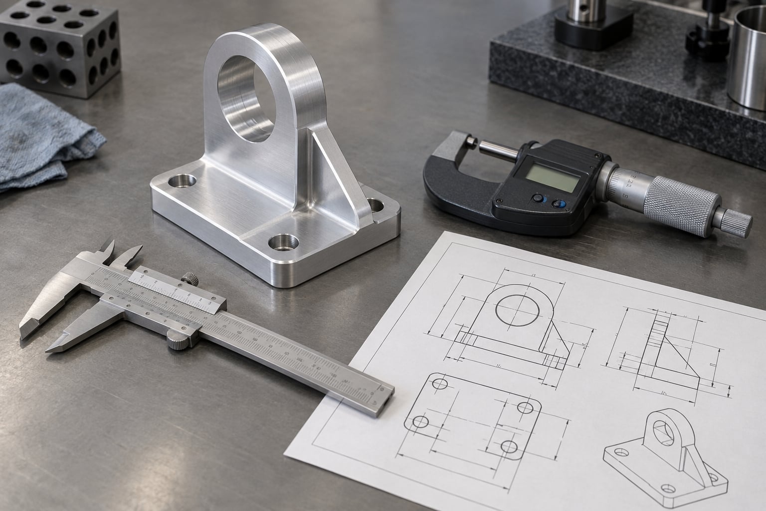
Standard CNC machining tolerances explained in plain terms: they are the allowable deviations above and below the nominal size that a machined feature may show and still work. There is no single number for every feature, so what “standard” really means is a set of industry defaults from ISO 2768, ASME Y14.5 and ANSI/ASME B4.1 that apply when a drawing does not call out anything tighter.
Standard CNC machining tolerances are the default allowable deviations applied to dimensions with no individual callout, governed by general tolerance standards such as ISO 2768-1 and ISO 22081. In practice a shop holds about plus or minus 0.005 in (0.13 mm) as-machined, plus or minus 0.002 in (0.051 mm) on precision work, and plus or minus 0.0005 in (0.0127 mm) on reamed holes. ASME Y14.5 covers geometric controls and ANSI/ASME B4.1 covers fits.
Most machinists I talk to will tell you the same thing: a tolerance is a functional decision, not a quality score. A part with every dimension at plus or minus 0.01 mm costs more, takes longer and fails more often than a part with two tight features and everything else left general.
Table of Contents
- Standard CNC Machining Tolerances at a Glance
- What Does a CNC Machining Tolerance Specify?
- What Are the Common CNC Machining Tolerance Levels?
- How Do Size, Position, Form, and Orientation Tolerances Differ?
- Which CNC Machining Tolerance Should You Choose?
- How Do Material and Process Capability Affect Tolerances?
- How Should You Write CNC Machining Tolerances on a Drawing?
- How Are CNC Machined Parts Inspected for Tolerance Compliance?
- How Do Tighter CNC Machining Tolerances Affect Cost and Lead Time?
- What Are Common CNC Machining Tolerance Examples?
- Frequently Asked Questions
- Conclusion: Start with Function, Not the Tightest Number
Standard CNC Machining Tolerances at a Glance
The short version of standard CNC machining tolerances: as-machined features commonly land within plus or minus 0.005 in (0.13 mm), precision milling and turning within plus or minus 0.002 in (0.051 mm), and reamed or ground features within plus or minus 0.0005 in (0.0127 mm). Those are typical capability figures, not guarantees.
Two families of tolerance notation appear on drawings. A bilateral tolerance allows equal deviation either way, written as a plus or minus value. A unilateral tolerance allows deviation in one direction only, which is common on a sealing face where you want no gap but will tolerate material standing proud.
| Precision level | Typical linear tolerance (in) | Typical linear tolerance (mm) | Typical angular | Where it applies |
|---|---|---|---|---|
| Rough / stock removal | plus or minus 0.020 | plus or minus 0.5 | plus or minus 2 degrees | Weldments, covers, non-functional bosses |
| General purpose as-machined | plus or minus 0.005 | plus or minus 0.13 | plus or minus 0.5 degrees | Most brackets, plates, housings |
| Fine machining | plus or minus 0.002 | plus or minus 0.05 | plus or minus 0.25 degrees | Mating features on a production part |
| Precision, ground or lapped | plus or minus 0.0005 | plus or minus 0.013 | plus or minus 0.1 degrees | Bearing seats, gauge features, reference faces |
| Ultra-precision | plus or minus 0.0001 or tighter | plus or minus 0.003 or tighter | plus or minus 0.05 degrees | Optical and instrument components, specialist finishing |
Every number in that table is a starting point for a conversation with the shop. Feasibility is decided per feature, per material and per setup, not per machine.
What Does a CNC Machining Tolerance Specify?
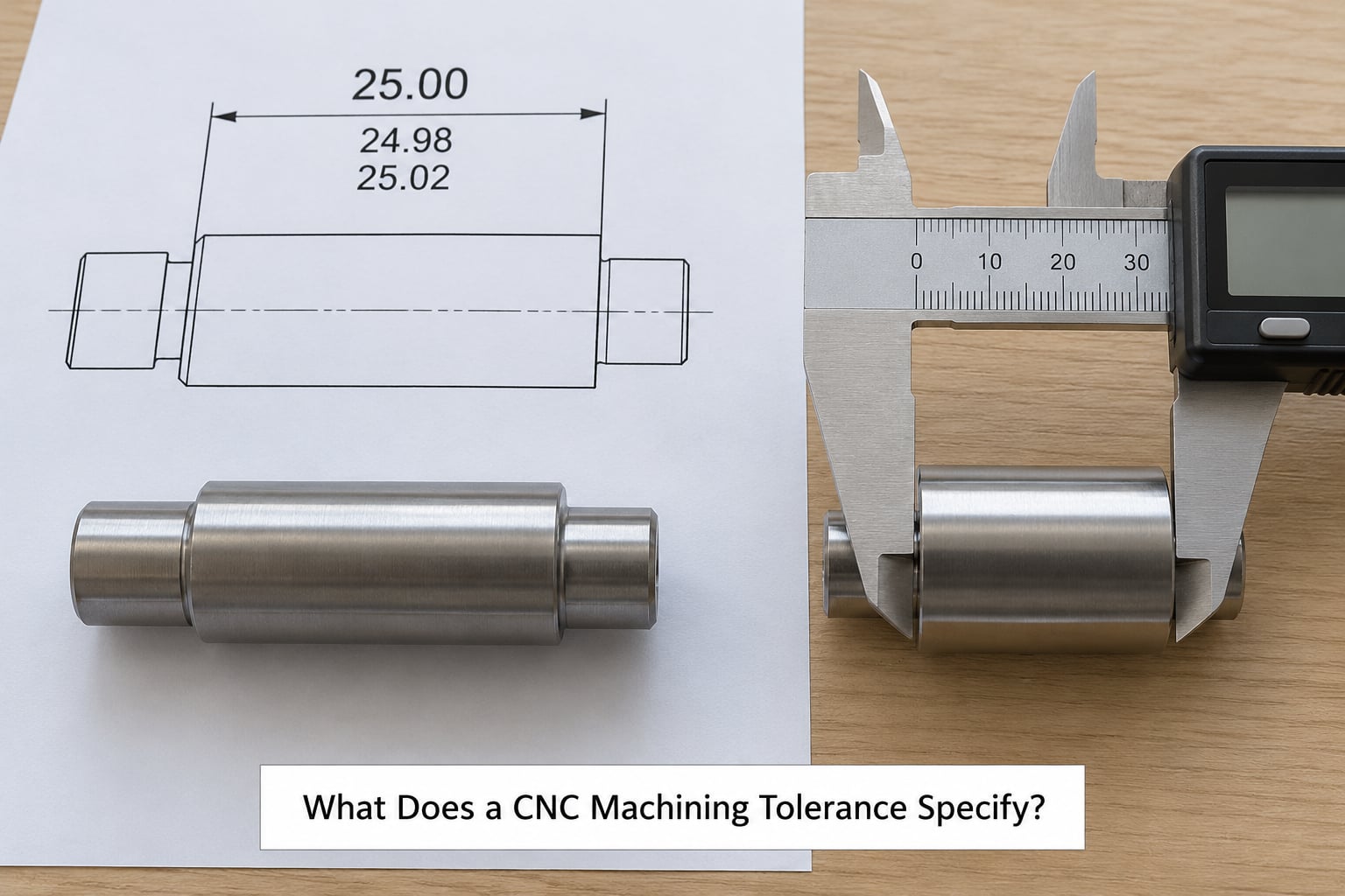
A tolerance answers one question: how far from the number printed on the drawing may the real part sit? It does not describe the whole shape, and it does not control how rough or how straight the surface is. Those need separate callouts.
Three values describe a linear tolerance: the nominal size, the upper limit and the lower limit. The tolerance is the total band between the limits, and the position of that band relative to nominal is the deviation.
Take a shaft called out as 25.00 mm. Written as 25.00 plus or minus 0.02 mm, the part may measure anywhere from 24.98 to 25.02 mm. A part at 25.019 mm passes. A part at 25.021 mm is scrap even though the difference is two microns, which is why inspection results get recorded against the drawing requirement and not against a general rule of thumb.
Unilateral notation states the two limits directly, so 24.98 to 25.02 mm means the same thing with no ambiguity about which side of nominal you are allowed to sit. Shops like limit notation for anything a customer measures directly on arrival.
What Are the Common CNC Machining Tolerance Levels?
Machining tolerance bands exist because process capability has limits. A 3-axis mill removing aluminum can hold about plus or minus 0.005 in without drama. Push the same feature to plus or minus 0.0002 in and the process changes completely: different tooling, slower cuts, a finishing operation, and a coordinate measuring machine on the inspection side.
The general tolerance classes below come from ISO 2768-1:1989, which is the standard most drawings still reference. The class letters stand for fine, medium, coarse and very coarse. Values are given for linear dimensions between 0.5 and 30 mm and again for the 30 to 120 mm band, because allowable deviation grows with nominal size.
| ISO 2768-1 class | 0.5 to 30 mm (mm) | 30 to 120 mm (mm) | Typical use |
|---|---|---|---|
| f (fine) | plus or minus 0.05 | plus or minus 0.1 | Small precision parts, instruments |
| m (medium) | plus or minus 0.1 | plus or minus 0.2 | General machined parts, default choice |
| c (coarse) | plus or minus 0.2 | plus or minus 0.5 | Larger castings and weldments |
| v (very coarse) | unlimited | unlimited | Features that are not dimensioned |
Two housekeeping notes on standards status. ISO 2768-2, which covered datums and datums in the general tolerance context, has been withdrawn and replaced by ISO 22081:2021. ISO 2768-1 itself is under revision, so confirm the edition your drawing calls out before a shop quotes against it.
Angular tolerance is usually specified in degrees: plus or minus 0.5 degrees on a general machined face, plus or minus 0.1 degrees after grinding. Angular capability depends heavily on the setup, because a head that is off by a fraction of a degree multiplies over the length of the part.
How Do Size, Position, Form, and Orientation Tolerances Differ?
Size tolerances control how big a feature is. Geometric tolerances control where it is, how it is shaped and how it is oriented relative to other features. A part can be dead on size and still be useless if the hole pattern is off position.
- Linear size applies to flat-to-flat dimensions and is written with a plus or minus value or limits.
- Diametral size applies to circles and cylinders and allows a different band because a hole and a shaft deviate radially rather than across a flat.
- Location controls where a feature sits relative to a datum. Position is the workhorse of hole patterns, and true position is its cylindrical form.
- Orientation controls how a feature points relative to datums: flatness, perpendicularity, parallelism, angularity.
- Form controls the shape of a single feature: straightness, circularity, cylindricity.
- Profile controls the whole outline of a surface or feature against its true shape, usually with an unequal distribution modifier.
- Runout controls how much a surface varies when the part is rotated about a datum axis, catching the wobble that the others miss.
All of these hang off a datum reference frame, shown as feature control frames attached to the drawing. A single symbol plus a value plus datum letters sits in a small box, and that box replaces the plain plus or minus callout for that feature.
Which CNC Machining Tolerance Should You Choose?
Choose the loosest tolerance that still lets the part perform its job. Work through these in order: what mates with this feature, how much assembly clearance the design tolerates, what the function actually requires, what material and feature size you are dealing with, what surface finish is needed, what quantity you are running, and what inspection method is realistic.
Ask the assembly question first. A hole that slides over a pin needs clearance and nothing more. A hole that carries a press-fit bearing needs interference, and the amount of it depends on the part, the housing material and whether you are cold or at temperature.
Then check feature size. The same plus or minus 0.05 mm is a much bigger deal on a 5 mm feature than on a 300 mm one, because the ratio of tolerance to feature size is what determines whether the process is stable.
When Should You Specify Tight CNC Machining Tolerances?
Specify tight CNC machining tolerances when the function cannot tolerate movement: bearing journals and press-fit seats, locating pins and dowels, precision mating faces, sealing and gasket surfaces, and reference features that drive a hole pattern. Medical and aerospace work sits in this group too, though there the tight tolerance comes with traceability requirements rather than the tolerance itself being unusual.
Here is what actually changes when a tolerance tightens. On the machining side: carbide or diamond tooling, lower feeds, a finish pass at low depth of cut, possibly a grinding or lapping operation, tighter fixturing, and temperature control on the coolant. On the inspection side: a coordinate measuring machine instead of calipers, tighter gauge control, and often sampling on fewer features.
Cost follows from that list. Slower cutting with more passes means shorter tool life and more tool changes. A finishing operation means a second setup or an outside process. A CMM program takes minutes per part, not seconds.
Setting Standard CNC Machining Tolerances by Feature
Set tolerances by feature, not by part. Every non-critical dimension inherits the general tolerance from the title block, and only the features that drive fit, function or assembly get an individual callout. This is the single change that most reduces both quote cost and scrap rate on a typical machined part.
Surface finish deserves its own line item. A feature can be dimensionally perfect and still leak, wear or look unfinished. Roughness average, Ra, is specified in micrometres in metric drawings and in microinches in inch drawings, and it is independent of the size tolerance.
| Surface finish | Ra in micrometres | Roughness in microinches | Typical process |
|---|---|---|---|
| Very rough | 12.5 | 500 | As-cast, as-forged, saw cut |
| Rough | 6.3 | 250 | Coarse milling, turning |
| Standard machined | 3.2 | 125 | General milling and turning |
| Fine machined | 1.6 | 63 | Finish pass, light cut |
| Precision ground | 0.4 | 16 | Surface or cylindrical grinding |
How Do Material and Process Capability Affect Tolerances?
Material decides how much the part will move while you cut it. Aluminium machines well and holds size, but it deflects more under tool load than steel, which is why shops slow feeds on aluminium rather than pushing a cycle time. Steel is more forgiving on deflection and less forgiving on thermal growth.
Engineering plastics behave differently again. They have higher thermal expansion than aluminium, they relax and creep after machining, and long thin walls move for days after the part leaves the fixture. Composites and composites-adjacent materials add abrasive edge wear and unpredictable fibre behaviour that can dull a tool mid-cut.
Difficult-to-machine alloys such as titanium and super alloys cut slowly and hold cutting forces that deflect both tool and workpiece. On those, achievable tolerance is a function of how much time the shop is willing to spend, not of machine nameplate.
Then there are the process factors that apply to everything. Tool wear drifts the size over a run, so a part cut at the start of a tool life can sit differently from one cut at the end. Stock removal and thin-wall deflection move the wall as the clamp releases. Each setup adds its own error, and stack-up across three setups is worse than any single one. Machine calibration and ambient temperature set the floor.
If you want a broader look at how inspection equipment fits into this, our guide to machine vision inspection systems explained covers where vision measurement fits and where a physical probe does not.
How Should You Write CNC Machining Tolerances on a Drawing?
Write the nominal size and the deviation in the same notation the rest of the drawing uses. Pick one measurement system for the whole drawing and declare it, because mixed metric and inch callouts are a genuine source of scrap.
Decimal-place convention carries meaning in imperial drawings. A dimension written to three decimal places in inches implies an accuracy of about plus or minus 0.005 in, which is a general tolerance rule of thumb rather than a callout. Do not rely on it for anything functional.
- Set a general tolerance note in the title block referencing ISO 2768-1 and the class you want, plus the measurement system.
- Give every functional feature an individual callout with bilateral, unilateral or limit notation.
- Declare units once and use them consistently.
- Show a datum reference frame on views where orientation matters, and pick primary, secondary and tertiary datums that reflect how the part is actually located in assembly.
- State the material condition, such as at maximum material condition, when you want tolerance bonus as the feature departs from worst-case size.
- Attach feature control frames for any location, orientation, form or profile requirement.
- Never leave a functional dimension blank or unresolved. An untoleranced feature that should be controlled is a shop assumption waiting to go wrong.
- Add a surface texture symbol wherever finish matters for the function.
One rule of thumb from the shop floor: the CAM programmer should choose tooling and process based on the tolerance, not the other way round. When a drawing arrives with plus or minus 0.01 mm on every dimension and only one feature matters, a good shop asks which one is critical before quoting.
How Are CNC Machined Parts Inspected for Tolerance Compliance?
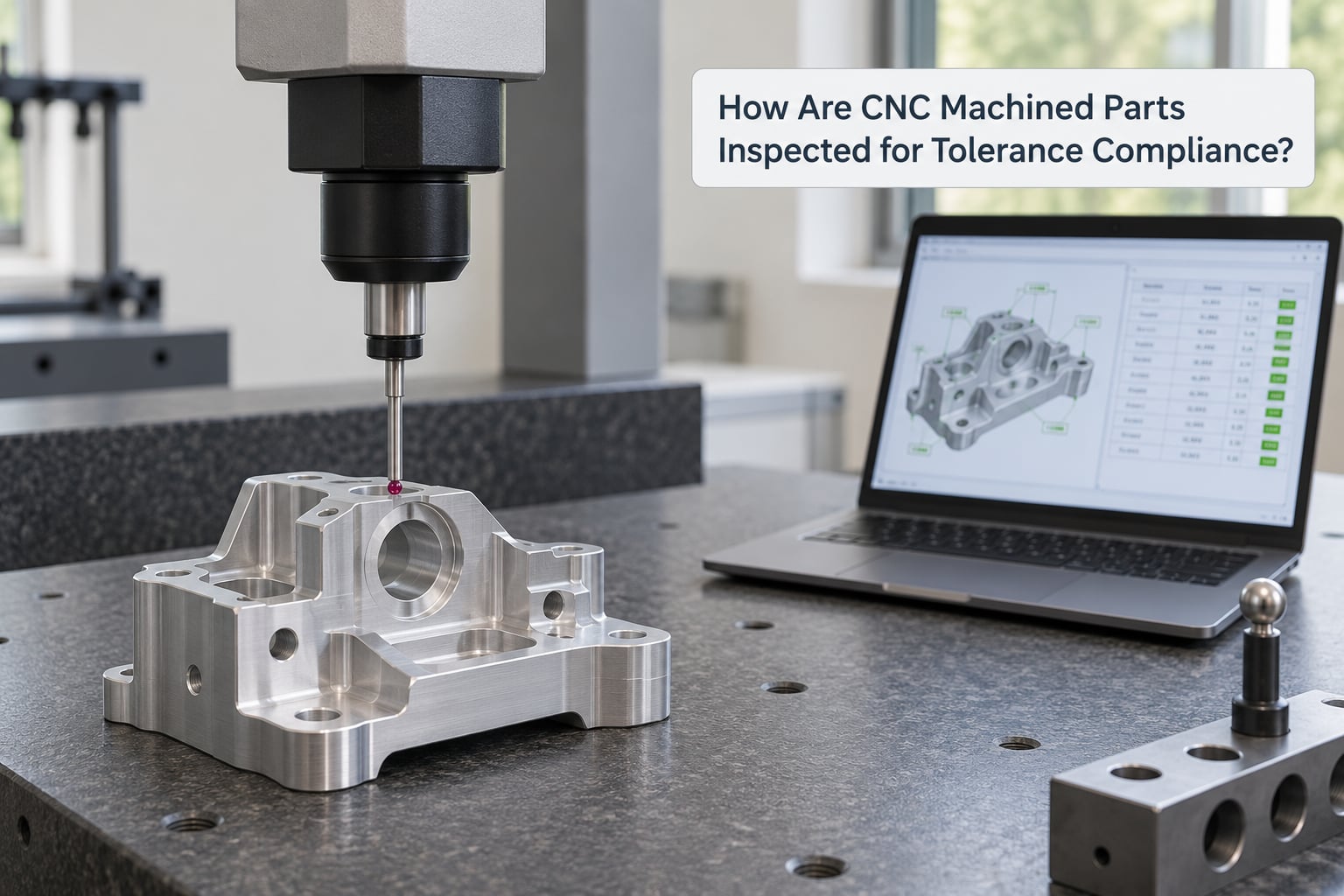
Inspection matches the tool to the tolerance. Vernier and digital calipers cover rough and general work, typically to about 0.01 mm or 0.001 in resolution. Outside micrometers handle shaft, boss and thickness dimensions. Height gauges and bore gauges cover large features and internal diameters.
A coordinate measuring machine handles hole positions, datums and anything geometric. Once you are specifying position at 0.1 mm or tighter, a CMM is usually the only sensible way to verify conformance, because a caliper simply cannot resolve the feature relationship.
The metrology rule most shops work to is simple: measure at least ten times more accurately than the tolerance you are judging. A 0.01 mm tolerance needs an instrument good to 0.001 mm, and it needs to be calibrated.
Near a specification limit, measurement uncertainty matters. ISO 14253-1 gives decision rules for declaring a part conforming or non-conforming when the measurement itself carries uncertainty, and guard banding is the practical response. Record actual readings against the drawing requirement rather than pass or fail impressions, and control temperature when the material or the tolerance is sensitive to it.
Sampling scales with the job. A prototype run gets a full first article inspection on a CMM. A production run typically uses a sampling plan agreed up front, with periodic audits. If you are weighing build versus buy, our make or buy decision analysis covers how that comparison usually gets framed.
How Do Tighter CNC Machining Tolerances Affect Cost and Lead Time?
Tight tolerances cost money in four places: machining time, tooling, inspection and scrap. The last one is the one buyers underestimate, because a process running at the edge of its capability will produce rejects no matter how good the setup was.
| Tolerance decision | Effect on machining | Effect on inspection | Effect on cost and lead time |
|---|---|---|---|
| General tolerance on most dimensions | Standard tooling, normal speeds | Calipers and micrometers, sampling | Baseline |
| Tight tolerance on two or three features | Finish passes, controlled feeds | CMM program plus in-process checks | Moderate increase |
| Tight tolerance on every dimension | Slow feeds, frequent tool changes, extra setups | Full CMM report on every part | Substantially higher |
| Very tight plus fine surface finish | Grinding or lapping operation | CMM plus roughness measurement | Highest, plus outside process cost |
| Thin-wall part at tight tolerance | Special fixturing, stress relief, slower cutting | CMM, distortion checks | High and unpredictable |
You can claw some of it back. Move tolerances to a common value so the shop can run one cutting strategy. Combine features into fewer setups. Ask for a costed tolerance band on the non-critical dimensions instead of a single number. If two parts each pass inspection and the assembly still does not close, the problem is usually stack-up, not either part.
What Are Common CNC Machining Tolerance Examples?
These five examples cover most real drawings, and each one is decided by a different requirement.
Clearance hole for a fastener
A mounting hole that a screw passes through freely needs room for the fastener and for thermal movement, nothing more. General tolerance on the diameter plus a position control on the pattern is usually enough. What matters here is location, not size.
Press-fit shaft into a housing
This is an interference fit, so the shaft is specified above nominal and the hole below nominal, with limits rather than a plus or minus value. The exact deviation depends on the shaft diameter and the housing material, and it needs to come from a fit calculation or a standard fit class rather than a guess. Compare the two systems carefully if you use them together: profile extrusion tolerances explained covers the same thinking for extruded profiles.
Sliding feature in a guide
A feature that has to move freely needs clearance on both sides plus a geometric control for straightness or cylindricity. Size alone will not stop it binding if the surface is bowed.
Flat mounting surface
A cover that has to seal needs a flatness control and a roughness callout, often with the tolerance placed all on one side of nominal so the part cannot stand proud. Flatness at 0.05 mm across a 200 mm face is a realistic ask on a well-supported setup; the same value on an unsupported thin plate is not.
Precision locating feature
A dowel hole or locating pin bore that drives the rest of the assembly is the classic critical dimension. Here you specify position to a datum reference frame with a material condition modifier, plus a size tolerance tight enough to fit the pin. This is where a title-block general tolerance genuinely does not apply.
Frequently Asked Questions
What is the standard tolerance for CNC machining?
A common as-machined standard CNC machining tolerance is plus or minus 0.005 in (0.13 mm) on general milled and turned features. Precision work usually holds plus or minus 0.002 in (0.051 mm), and reamed or ground features reach plus or minus 0.0005 in (0.0127 mm). These are typical capability figures rather than guarantees, because material, feature size, geometry and setup decide what is realistic.
Are CNC machining tolerances based on ISO standards?
Usually. ISO 2768-1:1989 supplies the general tolerance classes fine, medium, coarse and very coarse that cover any dimension without its own callout, and the ISO 2768-2 part was withdrawn and replaced by ISO 22081:2021. ASME Y14.5 covers geometric tolerancing and ANSI/ASME B4.1 covers fits. Regulated work adds quality system requirements under AS9100 or ISO 13485 on top.
Does CNC machining tolerance mean decimal places?
Not by itself, but in imperial drawings decimal places imply accuracy. A dimension written to three decimal places in inches carries an implied general tolerance of about plus or minus 0.005 in, and two decimal places implies about plus or minus 0.010 in. That convention is a fallback only. Functional dimensions should always carry an explicit callout rather than relying on how many digits were typed.
How do you measure CNC machining tolerances?
Match the instrument to the tolerance. Calipers suit rough work, micrometers cover shaft and thickness sizes, bore and height gauges cover internal and large features, and a coordinate measuring machine verifies hole position and geometric controls. The working rule is to measure at least ten times more accurately than the tolerance you are judging, with calibrated equipment and controlled temperature. Record actual readings against the drawing requirement.
Should all CNC-machined parts have tight tolerances?
No, and asking for them everywhere is the most common reason a machined part costs more than it needs to. Put tight limits only on the features that drive fit or function, such as bearing seats, locating pins, sealing faces and hole positions, and let everything else inherit a general tolerance from the title block. A part with two critical dimensions is cheaper, faster and less likely to be rejected than one with tight limits on all of them.
Conclusion: Start with Function, Not the Tightest Number
Standard CNC machining tolerances only matter in relation to what a part has to do. Decide the fit and the function first, list the features that actually drive them, and give those features a tolerance the process can hold consistently. Everything else can stay on a general ISO 2768 class.
Before a part goes to quote, confirm three things: which dimensions are critical, what tolerance and finish each one needs, and how the result will be inspected. Send that to the shop and ask them to confirm feasibility against the drawing rather than against a generic machine tolerance claim. That single conversation prevents most of the rejections I hear about.