
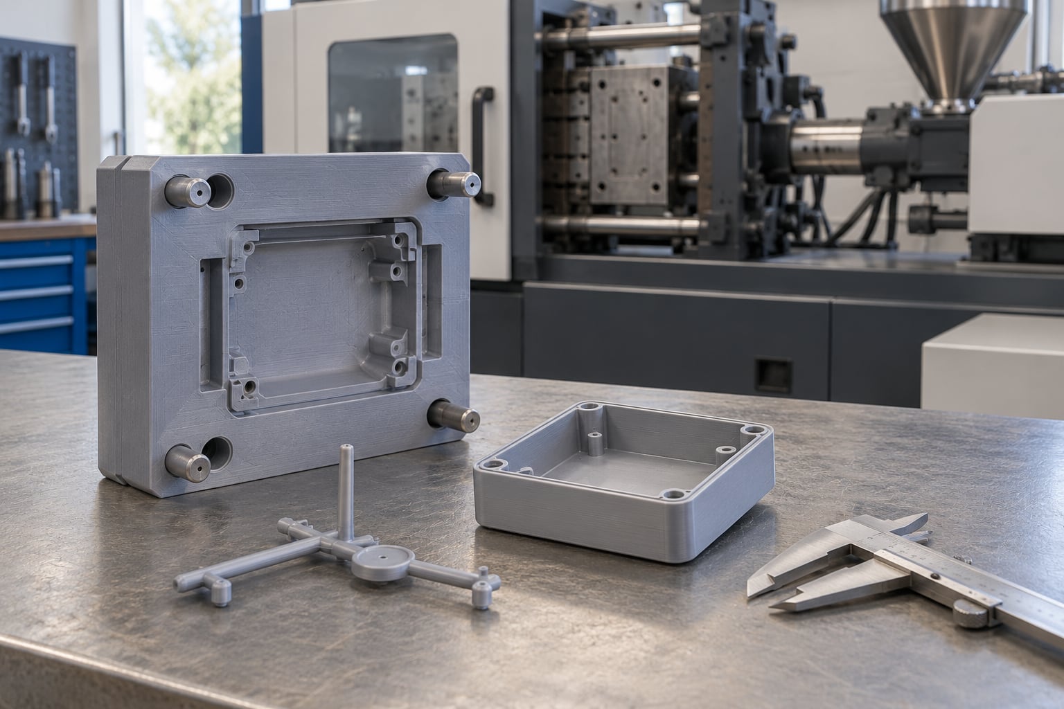
3D printed injection molds for short runs replace weeks of machined aluminum tooling with a print job that finishes in a day or two, and they can hold up to a few hundred shots of real engineering plastic before wear makes them unusable. They are not a cheaper version of production tooling — they are a different tool for a different job: getting validated, functional parts out of a design that has not earned a steel mold yet.
The line between a good use and a bad one is short. If you need a handful of parts to test fit and function, printed tooling is hard to beat. If you need tight cosmetic surfaces, hundreds of thousands of shots, or a material that melts above the printed tool can survive, you are asking for trouble.
This guide covers how printed tooling works, where it earns its cost back, how to design and validate one, and how to decide when to move on to metal.
Table of Contents
- 3D Printed Injection Molds for Short Runs: How They Work
- When 3D Printed Injection Molds Make Sense
- How to Design a 3D Printed Injection Mold for a Short Run
- Which 3D Printing Process and Mold Material Should You Use?
- How to Validate and Test the Mold Before Production
- What Are the Main Limitations and Failure Risks?
- How Do 3D Printed Molds Compare with Traditional Molds?
- How to Make the Short-Run Economics Work
- Frequently Asked Questions
- How many shots can a 3D printed injection mold last?
- Can injection molds be 3D printed?
- How much does it cost to make a 3D printed injection mold?
- What print technology is best for injection mold tooling?
- Can polypropylene be injection molded in a 3D printed tool?
- Are 3D printed molds suitable for production parts?
- What to Do First
3D Printed Injection Molds for Short Runs: How They Work
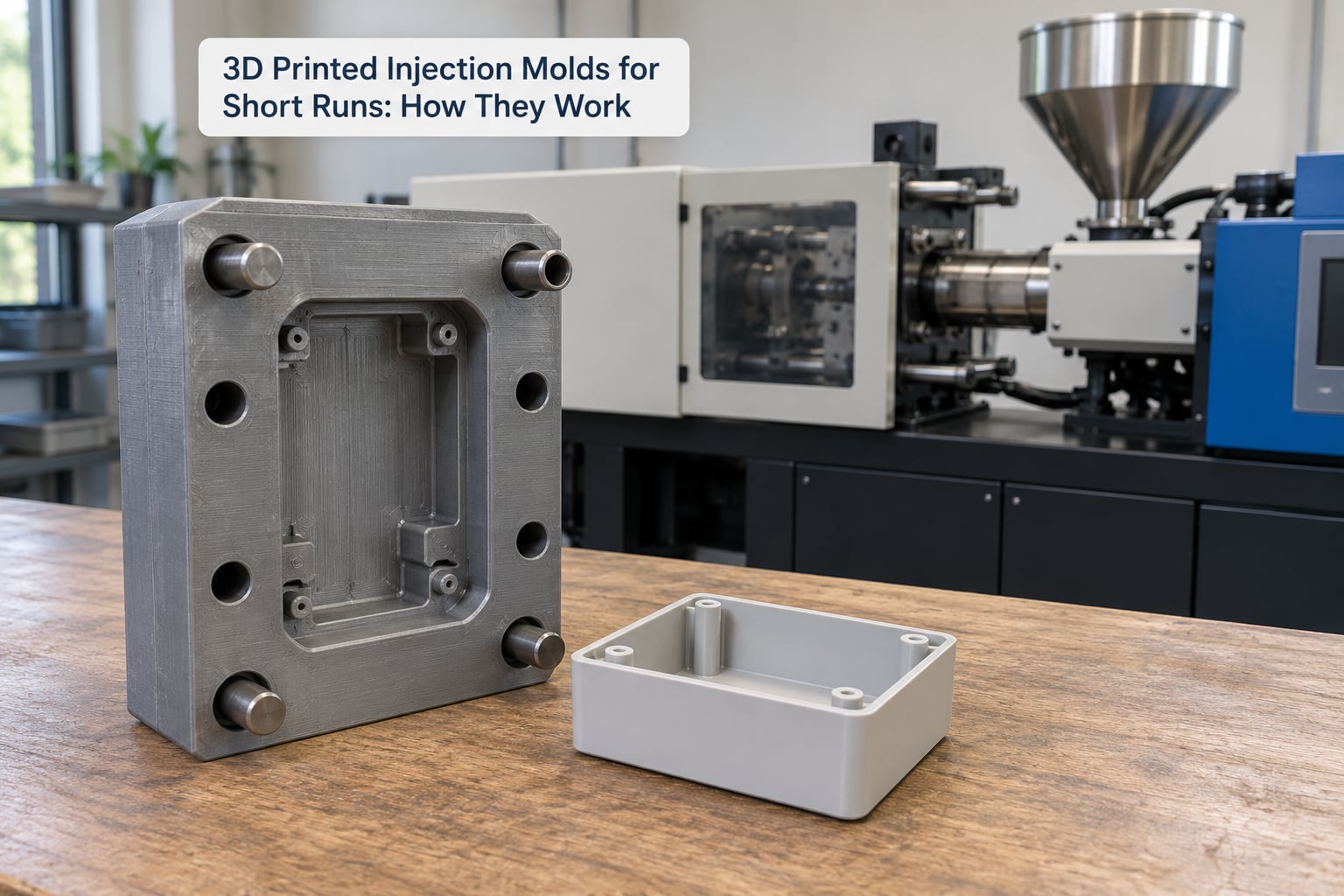
A 3D printed injection mold is a mold core and cavity insert produced by additive manufacturing, usually photopolymer resin, high-temperature filament, or a metal binder-jetted insert, mounted in a standard mold base and run on a conventional injection molding machine. In practice it behaves exactly like a machined insert during the shot, and differs only in thermal mass, surface finish and durability.
The workflow looks like this. Your part model is inverted and offset for shrinkage, split along a parting line, given draft and ejection features, then printed. The printed insert is pressed or bolted into a mold base with the ejector system and cooling lines. From the first shot onward, the machine sees a normal mold.
That last point matters more than it sounds. A printed cavity that is 0.1 mm out of position after installation still molds fine if your tolerances allow it, because the machine does not know what a “correct” mold looks like. What it does notice is heat, which printed polymer tools absorb and shed far more slowly than aluminum or steel.
Practitioners running printed tools for small batches describe them as definitely viable, while flagging lower thermal conductivity as the first thing you feel in cycle time. That single sentence is the honest summary of the technology.
When 3D Printed Injection Molds Make Sense
Printed tooling wins when the quantity is small enough that the amortization math never favors a machined tool, and the part is functional enough that a visual prototype will not tell you the truth. Below roughly 50 to 100 shots, printed tooling is usually the right answer for polymer parts.
Strong candidates share a few traits. Simple geometry without deep coring, thin uniform walls, a resin or low-melt polymer, and geometry that does not demand a polished surface. Also ideal: parts where the design is still moving and you want a free design change between runs, because reprinting an insert costs a day rather than a modification fee.
Printed tooling is also the natural path for liquid silicone rubber prototyping. No SLA or 3D material genuinely mimics silicone, so printed parts are commonly used as visualization models while the real LSR tool stays tool steel in a mold base. If you are molding LSR long term, the printed tool buys you geometry confidence, not production parts.
Other situations that work well:
- Pre-production builds where you need 50 to 300 functional parts for assembly, testing or a customer pilot.
- Bridge production covering the gap between design freeze and aluminum tool delivery.
- Market testing, where a small run of sellable parts beats a hand-assembled prototype.
- Jigs, fixtures and soft tooling that take wear but do not need cosmetic finish.
- Complex geometry that is expensive to machine, such as conformal channels or undercuts resolved by printing rather than side actions.
Conventional tooling wins in the opposite situations. Tight tolerances on mating features, Class A cosmetic surfaces, high-volume repeat orders, glass-filled or engineering resins with high melt temperatures, and any part that will see a lot of shots. Printed tools are also a poor match when cycle time matters more than startup cost, because you are waiting on the tool to cool between shots.
If you want the volume bands broken out numerically, the 3D printing vs injection molding cost breakdown walks through where each process crosses over.
How to Design a 3D Printed Injection Mold for a Short Run
Design for a printed tool by starting from the part and working backward to the machine, not by copying a metal mold drawing. A metal mold is a precision assembly that assumes rigid, dimensionally stable inserts. A printed insert is a polymer part that grows when it heats up, so your parting line and draft need to tolerate that growth.
Start from the part, not from a metal mold template
Decide which features actually need accuracy. A draft angle, a wall thickness, and a snap-fit lead-in can be generous. Hole positions, sealing surfaces and bearing fits need to be tight. Printing a metal mold design as a polymer insert without revisiting it usually wastes material and still misses on the critical dimensions.
Fillets beat sharp internal corners for two reasons. The polymer flows into a radius rather than fighting a corner, and a printed radius has fewer stress risers than a printed sharp edge. Corners under about 0.5 mm are a common source of first-shot short shots.
Give the tool draft, shutoffs and a parting line that closes cleanly
Draft is the most important number in the whole design. One to three degrees per surface is a reasonable starting point for printed tools, going higher on deep or textured features. Printed surfaces are rougher than machined ones, so stiction alone will eat into any draft you give it.
Shutoffs — the tiny lands where the mold closes tight enough to stop melt — need to be generous and flat. Polymer expands far more than steel, so a shutoff that works on a metal tool may gap and flash when the printed version is 150 degrees Celsius. Oversize the shutoff lands and accept a slightly larger flash ring.
The parting line itself should sit on a flat face, follow the longest path, and avoid crossing the thickest sections of the part. A stepped or offset parting line prints fine but closes unevenly and is where printed tools crack first.
Plan the insert and mold base architecture
Print inserts, not the whole mold. This is the single most practical decision people miss. Beginners print an entire mold and then discover they still need a mold base frame, ejector system, guide pins and a way to mount it on the platen — all of which cost money and none of which printing solves.
Design the insert as a rectangular block with standard mounting features that drops into a commercial mold base. You get alignment, ejection and cooling from bought hardware, and the printed part carries only the geometry.
For ejection, use metal ejector pins of standard diameter rather than printed ejectors. Printed ejector pins deform within a few cycles. Where the part will not release, put a printed lifter sleeve or blade around a metal pin so the force lands on printed material and the pin carries the load in shear.
Budget for shrinkage and thermal growth
Two separate corrections are needed. The first is material shrinkage: typical polymers shrink roughly 0.3 to 2 percent depending on grade and fiber content, so scale the cavity by that factor before printing. Polypropylene and fiber-filled grades sit at the high end.
The second is the mold itself growing as it heats. Printed tools expand more than aluminum, so a cavity that fits tight when cold will be slightly oversize when hot. Leave a little more clearance than you would on a metal tool rather than fighting it with tight shutoffs.
Print orientation is a strength decision, not a detail. Layers bond poorly along their Z direction, so orient the insert so that the highest injection pressure pushes perpendicular to layer lines, and so ejector force pushes perpendicular to layer lines too. A tall thin printed tool standing on end is usually stronger than the same tool laid flat.
Which 3D Printing Process and Mold Material Should You Use?
SLA and DLP photopolymer resin is the default choice for most printed tooling, because cured resin gives the stiffness, dimensional stability and surface finish that the FDM and jetting processes cannot match at this scale. FDM is cheaper and works with commodity printers for low-demand polymers. Material jetting gives the best surface but limited size and temperature resistance. Metal binder jetting is the interesting outlier for wear-critical inserts.
| Process | Typical materials | Max practical melt temp | Surface finish | Expected shot life | Where it fits |
|---|---|---|---|---|---|
| SLA / DLP | High-temp and toughened resins | Around 120 to 150 C melt | Fine, machined-looking after sanding | 100 to 500 shots, geometry dependent | Default choice for functional short runs |
| FDM | Carbon or glass filled PC/ABS, nylon blends | Around 100 to 130 C melt | Layered, needs finishing | Few dozen to low hundreds of shots | Cheap, in-house, forgiving polymers |
| Material jetting (PolyJet) | Photopolymer plus soluble support | Low to moderate melt temp | Best in class, near final finish | Few hundred shots on soft resins | Visual parts, soft tooling, geometry studies |
| Metal binder jetting | Steel or bronze infiltrated | Full engineering melt range | As-printed or lightly machined | Thousands of shots, wear dependent | Durable wear inserts inside a printed core |
| Composite printed tooling | Printed core with printed or machined inserts | Set by the insert material | Part quality, part machined | Hybrid, insert life governs | Extending life where wear is concentrated |
On materials, match the tool to the melt temperature with headroom. Most printed tooling fails not from a single event but from cumulative thermal cycling, so continuous headroom matters more than a single temperature rating on a datasheet. Below roughly 80 C melt you are comfortable with standard toughened resins. Between 80 and 120 C you need high-temperature formulations and printed-in cooling. Above 120 C, printed polymer tooling stops being a good idea and you should be looking at a machined aluminum insert or a hybrid tool.
Print filled filaments for stiffness, and remember that the filler changes the surface badly. Glass-filled ABS and PC print like metal and sand like glass, so the wear surface needs machining or a coating before it touches a part.
Before you commit, read our aluminum vs steel molds pros and cons guide — the decision you are really making in a hybrid tool is printed polymer versus machined aluminum.
How to Validate and Test the Mold Before Production
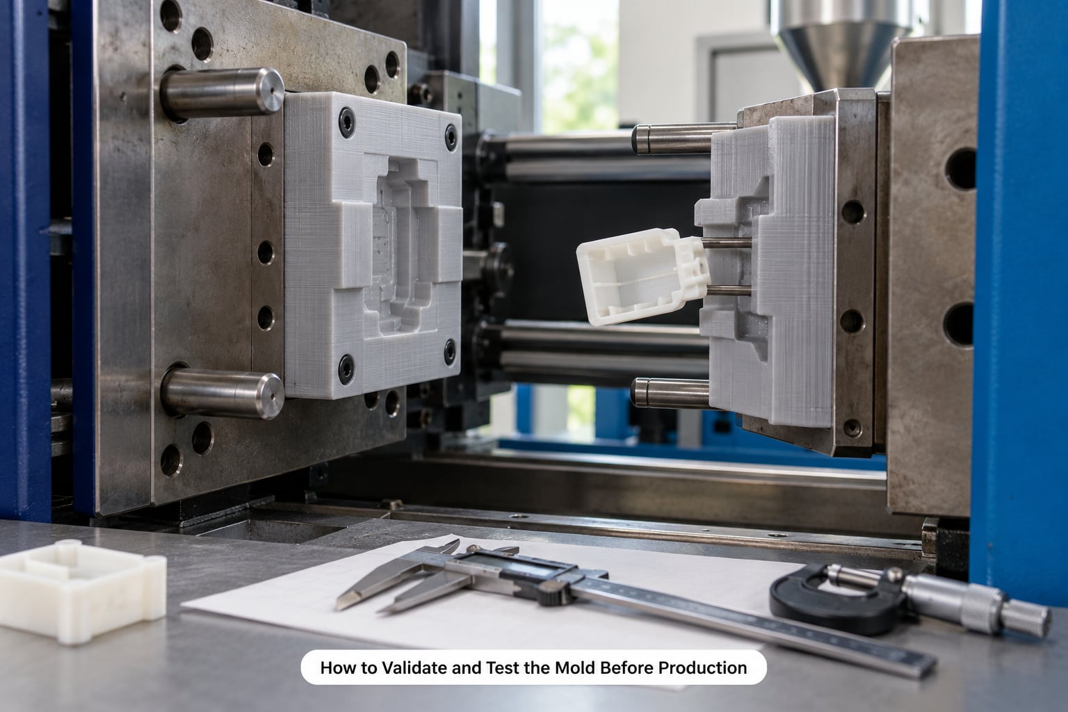
Validation takes an afternoon and prevents a scrapped run. Work through it in order and do not skip to production shots, because a printed tool that was never debugged will mark parts long after the interesting failure has passed.
- Inspect the insert dry. Look for delamination, visible layer gaps, warpage off the platen and voids in high-pressure regions. Run the insert against a granite plate with a feeler gauge; a bow greater than a few hundredths of a millimeter will close unevenly.
- Check the parting line by hand. Close and open the empty mold several times. You should feel consistent resistance, not a sudden bind at one point. Fix any interference with a file before the mold ever sees plastic.
- Install and center. Use the mold base’s guide pins and verify the insert is parallel to the platen with a dial indicator on two axes. A printed tool that is off-square produces asymmetric flash and uneven shrinkage.
- Establish parameters conservatively. Start with a low melt temperature within the resin supplier’s range, moderate injection pressure, and a longer than usual hold. Then step each one up in small increments.
- Run representative shots. Make ten to twenty parts, not one. Watch the first shot for cold slugging and short shots, which on printed tools usually mean venting is insufficient or the gate is too small.
- Measure and record. Check the critical dimensions on ten parts spread through the run, plus cosmetic surfaces and gate vestige. Write down melt temperature, hold pressure, hold time, back pressure, cooling time and screw speed.
- Re-check after thermal soak. Let the tool sit through 100 shots, then measure again. Dimensional drift at that point tells you whether your shrink factor was right, and it is much cheaper to learn here.
That parameter sheet is the most valuable thing you produce. When you run the next batch three weeks later with a fresh insert, you start from known settings instead of guessing again.
What Are the Main Limitations and Failure Risks?
Printed tooling fails predictably once you know the pattern. The dominant risk is heat accumulation: polymer tooling insulates, so melt temperature climbs shot after shot until the resin softens, deflects or takes a permanent set.
| Failure mode | What it looks like | Main cause | How to reduce it |
|---|---|---|---|
| Creep and growth | Cavity slowly grows; parts flash and drift out of tolerance | Repeated pressure plus heat on polymer | Lower melt temp, steel inserts at wear points, realistic run planning |
| Heat buildup | Cycle time climbs, melt degrades, color shifts | Low thermal conductivity in printed tool | Printed-in cooling lines, longer cool time, reduced shot rate |
| Layer delamination | Crack opens across the parting line or at a sharp corner | Print orientation and insufficient layer bonding | Reorient the insert, heat the chamber, avoid printed stress risers |
| Parting line chipping | Tool cracks at the shutoff or parting land | Shutoffs too small, excessive mold expansion | Oversize shutoff lands, flatter parting line, reduce melt temp |
| Ejector failure | Part sticks, marks deform, printed ejectors shear | Printed ejectors too weak, draft too low | Standard metal ejector pins, printed lifters, more draft |
| Surface marking | Visible layer texture, gate vestige, ejector marks | As-printed surface transferred to the part | Finish wear surfaces, gate on a hidden face, polish selectively |
| Warpage | Insert bows, part distorts, flash is uneven | Residual stress in the print, uneven heating | Longer anneal before install, metal plates for stiffening, lower shot rate |
| Vent blockage | Short shots, burns at the end of flow | Vents too small or printed over | Design generous vents and vent plugs that can be cleaned |
Two risks get less attention than they deserve. The first is vendor stability: additive tooling is a young enough market that consolidation and shutdowns are still common, and projects built around an acquired technology can stall with the vendor. Ask who owns the process and who will still be printing in three years.
The second is minimums. Service bureaus quote unclear minimums and long lead times, with quick-turn tool steel core and cavity sets commonly running three to seven weeks even when expedited. Get the actual shot count and lead time in writing before you design around a supplier.
The honest distinction most people are actually looking for is this. A printed tool used for visual and fit validation is low risk. A printed tool used for structural or cosmetic production parts is a real commitment, and you should plan it as one.
How Do 3D Printed Molds Compare with Traditional Molds?
Printed tooling wins on startup cost, lead time and design freedom, and loses on life, cycle time, surface finish and dimensional stability. The table below is the honest comparison.
| Criterion | 3D printed mold | CNC aluminum mold | Production steel mold |
|---|---|---|---|
| Upfront tooling cost | Low, often a small fraction of machined | Moderate | High |
| Tool lead time | Days | Weeks | Weeks to months |
| Shot-to-shot repeatability | Acceptable within a thermal band, drift over a run | Excellent | Excellent |
| Expected life | Dozens to a few hundred shots | Tens of thousands | Hundreds of thousands to millions |
| Cycle time | Longer, cooling limited by the tool | Good with conventional cooling | Best, full cooling circuits |
| Part surface finish | Layer texture unless finished; gate vestige | Machined or textured to spec | Polished or EDM texture to spec |
| Tolerance hold over a run | Weakest area; expect drift as the tool heats | Stable | Stable |
| Design changes | Free, reprint the insert | Costly modification | Costly modification |
| Complex geometry | Strong, conformal cooling and undercuts easy | Possible but slow and expensive | Same |
| Material range | Low and moderate melt thermoplastics, LSR visualization | Full engineering range | Full engineering range |
| Best fit volume | 1 to a few hundred parts | A few thousand and up | Tens of thousands and up |
The pattern nobody wants to hear: printed tooling does not scale. Practitioners report that once you are into the hundreds, print time and material consume the savings, and startup founders reject printing at their target volume outright. For those runs, a low-volume molding service is the better tool.
How to Make the Short-Run Economics Work
The economics are simpler than most tooling spreadsheets suggest, because the printed tool’s cost is small and its failure risk is the thing to watch. Build the model from four lines: print time, print material, finishing, and the labor to install and validate.
Start from shot count rather than part cost. A printed insert that took 30 hours of machine time and finished cleanly can support a few hundred shots. The useful calculation is total printed tool cost divided by shots, added to the molding machine and material cost per part. That number has to land below what a machined tool would deliver at the same volume — and at a few hundred shots it usually does, but the margin narrows quickly as the shot count climbs.
| Component | What drives it | How to control it |
|---|---|---|
| Machine time | Insert volume, layer height, print orientation | Print at the coarsest layer height the finish can tolerate; orient to cut supports |
| Print material | Resin or filament volume and grade | Use shell thickness where a full solid adds nothing but mass |
| Finishing | Sanding, machining wear surfaces, polish | Design wear surfaces as separate machined inserts rather than finishing printed faces |
| Mold base and hardware | Frame size, ejector set, guide pins | Buy a standard base rather than printing structure |
| Labor | Installation, alignment, parameter setup, measurement | Reuse the validated parameter sheet on every run |
| Risk of a scrapped run | Tool life, part design, parting line design | Run 10 to 20 validation shots and measure before committing the order |
Two levers move the number more than anything else. The first is cooling: adding printed-in channels buys back cycle time on every shot, which is where most people underestimate the cost. The second is the decision about where the tool will wear — putting a machined insert at the gate, the shutoffs and any ribbed wear surface keeps the printed geometry doing the structural work.
Plan the transition from the start. Once a printed tool proves the design, the same CAD part moves to an aluminum tool with minimal redesign, so nothing is wasted. If you want a framework for pricing that next step, see how to calculate injection molding tooling cost.
Frequently Asked Questions
How many shots can a 3D printed injection mold last?
Realistic shot life runs from a few dozen to a few hundred shots for most printed tools, and the variables matter more than the headline number. Cycle time, melt temperature, cavity pressure, wall thickness, geometry and resin grade all change the result, so a thick part run hot dies far sooner than a thin one run cool. Treat a few hundred shots as a planning figure, validate on ten to twenty shots, and re-measure part dimensions periodically during the run.
Can injection molds be 3D printed?
Yes. Additive manufacturing is widely used to produce injection mold cores and cavities for short runs, typically from photopolymer resin, high-temperature filament or infiltrated metal. The printed insert mounts in a standard mold base and performs like any other insert during the shot. What changes versus machined tooling is tool life, cycle time and surface finish, not whether the molding process works at all.
How much does it cost to make a 3D printed injection mold?
A printed tool costs a small fraction of machined aluminum tooling, largely because the machine time replaces skilled cutting and finishing. The bulk of the cost is the mold base, ejector hardware and your labor to install and validate, not the material. Print-time and material figures vary widely with insert size and geometry, so the honest answer is a range tied to a specific part and shot count, not a single number.
What print technology is best for injection mold tooling?
SLA or DLP photopolymer resin is the best default for functional short-run tooling because cured resin is stiff, dimensionally stable and near isotropic. FDM filled filaments work when the budget matters most and the polymer has a modest melt temperature. Material jetting gives the best surface finish for visual parts, and metal binder jetting suits wear-critical inserts inside a hybrid tool.
Can polypropylene be injection molded in a 3D printed tool?
Polypropylene can be molded in a printed tool, but it sits at the demanding end of the range. Its melt temperature is higher than most standard resins tolerate for long, and it shrinks more than unfilled thermoplastics, so your cavity scale factor needs adjusting. Keep melt temperature at the low end of the recommended range, allow generous cooling time, and expect fewer shots than with a low-density polyolefin such as HDPE.
Are 3D printed molds suitable for production parts?
Yes for short runs of functional parts, with conditions attached. Printed molds suit validation builds, pre-production pilots, bridge production and market-test runs of tens to a few hundred parts. They are not a substitute for aluminum or steel when you need tight tolerances held across a long run, polished surfaces, or hundreds of thousands of shots. Plan the move to metal tooling as volume grows.
What to Do First
Count your shots, not your parts. If the run is under a few hundred and the melt temperature fits your print material, model the insert as a drop-in for a standard mold base, give it one to three degrees of draft, and print it. Then debug on ten shots and measure before you order the batch.